1
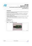
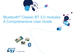
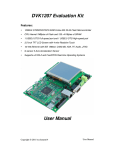
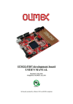
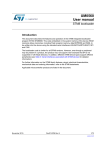
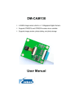
Embedded Connectivity May 2012 Embedded connectivity Stands for the integration of built-in wired and wireless communication interfaces including software and communication protocol support in non-phone devices, machines and vehicles and thus enables the rapid introduction of compute solutions to meet the sector's ever evolving needs Embedded Connectivity - June 2012 2 Demo Session Embedded Connectivity 802.15.4 @ 2.4GHz STM32W + MEMS Wireless Sensor Gateway Wireless SubGHz Communication with SPIRIT-I and STM32L 13.56MHz ISO15693 / NFC RFID Solutions Embedded Ethernet Embedded Connectivity - June 2012 3 Content • Demo Session: Embedded Connectivity • Sub GHz Solutions based on SPIRIT-1 • MBUS and KNX Communication Protocols for Smart Buildings and Smart Grid • STM8L/STM32L1: Ultra Low Power Microcontroller for wireless communication • Bluetooth Modules with embedded Firmware and BT Smart outlook • Solutions for 13.56MHz (ISO15693 / RFID / NFC) • Solutions for 2.4GHZ 802.15.4 (STM32W , STM32L1W, GreenNet) • Embedded Ethernet • Solution for CANopen on STM32 • Powerline Communication for Metering Embedded Connectivity - June 2012 4 Application Drivers towards 2015 40% 35% SSD 30% Tablets 25% Smartphones (4G CAGR > 100%) 2011 - 2015 CAGR 20% Building & Home Automation 15% Energy Generation & Distribution Fiber Broadband 10% Appliances Medical HDD Ebooks STB 5% WLAN Acess/Routers Fab Automation Infotainment Game Consoles Automotive Body TV 0% Computer Systems Printer -5% Flat Panel Monitor -10% Mobile Phone 1G/2G -15% -20% 100 1.000 10.000 Market Size in 2015 (K$) Automotive Electronics Categories Consumer Electronics Categories Data Processing Categories Industrial Electronics Categories Wired Communications Categories Wireless Communications Categories Source : IHS iSuppli Embedded (SAM, ie excl DRAM, Flash, MPUs,Connectivity Opto) - June 2012 100.000 5 SPIRIT1 sub GHz RF transceiver What is SPIRIT1 ? • Low power RF Transceiver, intended for RF applications in the sub-1 GHz Band, with integrated packet handler targeting Smart Metering Applications • Designed to operate in 169 / 315/ 433 / 868 / 915 MHz, Frequency Bands ISM (Industrial, Scientific and Medical) and SRD (Short Range Device) • For Systems with channel spacing down to 12.5 kHz, complying with the EN300 220 standard. • Applications • • • • • Wireless Metering and Wireless Smart Grid (AMR and ISM) Home & Building Automation Wireless Sensor Network (WSN) Industrial Monitoring and Control Wireless Fire and Security Alarms • Suitable for Systems targeting compliance with : • Europe • US • Japan ETSI EN 300 220 FCC CFR47 Part 15 ARIB STD T-67 • Europe Systems targeting compliance with the Wireless MBUS standard EN 13757-4:2005, EN13757-4:2011 • Main operating parameters controlled via SPI • Integrated SMPS allowing very low power consumption Embedded Connectivity - June 2012 7 • Wide supply voltage range from 1.8 V to 3.6V Key Features • Configurable data rate from 1 to 500 kbps • Supported modulation schemes: 2-FSK (Binary Frequency shift keying), GFSK (Gaussian Frequency Shift Keying), MSK (Minimum Shift Keying) GMSK (Gaussian Minimum Shift Keying), ASK (Amplitude Shift keying) / OOK ( On-off keying) • RF Receiver • Excellent receiver sensitivity (169 MHz) • - 120 dBm at 1.2 kbps • - 103 dBm at 50 kbps • Adjacent channel selectivity (1% PER – 20 bytes packet length) • 55 dB at 12.5 kHz channel spacing • Blocking performance : • -28 dBm at 10 MHz offset, -36 dBm at 2MHz offset • IIP3 (Input third order intercept) • (Input Power -50 dBm 915 MHz) : -31 dBm • RF Transmitter • Programmable Output Power -36 dBm to +11 dBm, in 0.5 dB steps Embedded Connectivity - June 2012 8 Key Features • Integrated SMPS allows very low power consumption Power mode Power consumption Description Shutdown 2.5 nA Everything off Standby 650 nA SPI On, register retention Sleep 950 nA SPI on, register retention, Wakeup timer on Ready 400 uA SPI on, XTAL on RX 9 mA * SPI on, XTAL on, RF Synth on TX 21 mA** SPI on, XTAL on, RF Synth on • SPI access is available in all the modes (except Shutdown) since the SPI block is powered by a dedicated LDO (no SMPS required) • * (9mA RX, 433 MHz, FSK, 38.4kbps), similar also for other bands; SMPS ON, Vcc = 3.0V • ** (21mA TX, +11dBm, 169 MHz) Embedded Connectivity - June 2012 9 Key Features • Peripherals & Support functions • Integrated packet handler, Support for Automatic acknowledgment of received packets, retransmission and time-out protocol • Automatic clear channel assessment (CCA) Engine : • Channel access mechanism, based on the rule ‘’Listen-before-talk’’ systems before transmitting ; this avoids the simultaneous use of the channel by different transmitter. • AES 128-bit encryption co-processor is available for secure data transfer • Separate 96-byte RX/TX FIFOs, accessible via the SPI interface for host processing • Supports frequency hopping under MCU control • Calibration can be made each time the MCU decide to change frequency or MCU can save and restore calibration data to make the frequency hopping faster • Package QFN 20 (4 x 4 mm) Embedded Connectivity - June 2012 10 Main Block Description • Data link layer • Support for channel configuration, packet handling and data buffering • Support Packet Formats (Basic, Stack, Wireless M-BUS ) • The Host MCU can stay in power down until a valid RF packet has been received, and then burst read the data, greatly reducing the power consumption and computing power required from the host MCU • AES encryption co-processor • Provides data security support as it embeds an advanced encryption standard (AES) core which implements a cryptographic algorithm • Analog temperature sensor • The Host MCU can be used to read the chip temperature (e.g. it can be used to force radio recalibration) • Battery indicator and low battery detector Embedded Connectivity - June 2012 11 MCU interface SPIRIT1 SPI communication • • • 12 Write registers or FIFOs Read registers or FIFOs 17 Commands (State diagram, AES, FIFO flush) MISO MOSI CLK CSN SPI GPIO SDN GPIO 0 GPIO 1 GPIO 2 GPIO 3 SHUTDOWN GPIO communication • • • • • • Interrupt signals Monitoring signals () Commands (TX/RX mode, Wake-up from external input) Input/output data (direct mode) Input/output reference clock (MCU clock out, 34.7 kHz for LDC mode input) Analog output: temperature sensor (GPIO 0) SDN pin • Shutdown signal The SPIRIT1 has more than 200 registers for flexible usage of the transceiver Embedded Connectivity - June 2012 SPIRIT1 SW Library An abstraction layer is provided. Each module of the library manages a specific feature of the SPIRIT1. AES CALIBRATION COMMANDS CSMA DIRECT RF GENERAL GPIO IRQ LINEAR FIFO PACKET COMMON PACKET BASIC PACKET MBUS PACKET STACK REGISTERS QI RADIO TIMER TYPES The SPIRIT1 library is developed in order to be platform independent. Every API function translate the high level command in a bit sequence to program the SPIRIT1. 13 SPIRIT1 SDK Suite GUI RF performance evaluation • SPIRIT1 contains a GUI allowing to perform: • • • • • Radio configuration RF tests (TX of un modulated carrier, TX PN9 sequence, RX activation) Packet transmission/reception test with PER evaluation AES engine encryption/decryption tests Register read/write and dump 14 SPIRIT1 Kits Part number Type Purpose Content Dev kit RF performance evaluation, Point to Point RF communication, System Prototype development 2 x STM32L based motherboard 2 x SPIRIT1 RF modules 15 Order code STEVAL-IKR001V1 (169 MHz) STEVAL-IKR001V2 (315 MHz) STEVAL-IKR001V3 (433 MHz) STEVAL-IKR001V4 (868 MHz) STEVAL-IKR001V5 (915 MHz) STEVAL-IKR001V6 (920 MHz, ARIB T-108) Embedded Connectivity - June 2012 15 ST with 3rd parties supports • STM32L + SPIRIT-1 • STM32L + KNX Transceiver • STM8L + KNX Transceiver Solutions for Smart Buildings • STM32F4 + KNX Transceiver Embedded Connectivity - June 2012 16 ST Wireless M-BUS Stack features 17 EN13757-4:2005 (S1, S1m, T1, T2, R2). • Radio band: 868 MHz EN13757-4:2011 (N mode) • Radio band 169 Mhz • GUI over USB Interface • Features under development: • Device type: Meter/Concentrator/Sniffer USB-HID WM-BUS SOFTWARE APPLICATION Database (MS-SQL Server Compact) Embedded Connectivity - June 2012 STM8L/STM32L1 EnergyLite™ platform – Ultra-low-power devices Flash memory size (in bytes) 8-bit and 32-bit MCU families 1M 19 32-bit core High-performance & Ultra-low-power 128 K Standard voltage & Ultra-low-power 16 K 2K • STM8S Mainstream • STM8A Automotive • STM8L Ultra-low-power • STM8T Touch-sensing • STM32F4 – Cortex-M4 • STM32F2 – Cortex-M3 • STM32F1 – Cortex-M3 • STM32F0 – Cortex-M0 • STM32L1 – Cortex-M3 - Ultra-low-power 8-bit core Features Embedded Connectivity - June 2012 STM8L/STM32L1 - Ultra-low-power MCUs • With the EnergyLite™ platform, STMicroelectronics is strongly committed to ultra-low-power MCUs • Energy saving • Ultra-low-power advanced architecture • High-performance core • Ultra-low-power in dynamic and static modes • New STM8L/STM32L1 series increase STM8/STM32 offer • Enriches both the ultra-low-power EnergyLite™ platform and STM8/STM32 portfolio • More than 100 part numbers for ultra-low-power lines Embedded Connectivity - June 2012 20 Ultra-low-power portfolio 21 • ST’s 130 nm ultra-low-leakage process technology Notes: 1. 80 pins for STM8L15x/16x only 2. BGA100 on STM32L15x up to 128 Kbytes only Legend: STM8L: 151 without LCD, 152 with LCD and 162 with LCD and 128-bit AES STM32L1:151 without LCD, 152 with LCD and 162 with LCD and 128-bit AES Embedded Connectivity - June 2012 Ultra-low-power series – 3 lines Common core peripherals and architecture: Multiple communication peripherals USART, SPI, I²C Feature-rich 32-bit solution: STM32L151/152/162 line 32 MHz CortexM3 CPU Up to 384-Kb yte Flash / Dual bank / RWW Up to 48-Kby te SRAM BOR PVD Main osc. input 1-24 MHz Up to 12Kbyte data EEPRO M RTC with 32 kHz osc. Up to 12 channe l DMA 12-bit ADC (1 μs) 2x 12-bit DAC LC D 8x4 0 4x4 4 AES 128bit Up to 4 channe l DMA 12-bit ADC (1 μs) 12-bit DAC LC D 8x4 0 4x4 4 AES 128bit ULP MSI MP U ET M US B FS SDI O Multiple timers Feature-rich 8-bit solution: STM8L151/152/162 line Internal 16 MHz and 38 kHz RC oscillators STM8 core @ 16 MHz Up to 64-Kb yte Flash Up to 4-Kbyt e SRAM BOR PVD 2x watchdogs Reset circuitry POR/PDR 2x comparators 22 Main osc. input 1-16 MHz Up to 2Kbyte data EEPRO M RTC with 32 kHz osc. Entry level 8-bit solution: STM8L101 line STM8 core @ 16 MHz Up to 8-Kbyt e Flash* Up to 1.5-Kby te SRAM Touch sensing Note: * Embedded EEPROM in the Flash Embedded Connectivity - June 2012 FSM C 3x opamp s STM8L – Ultra-low-power modes Embedded Connectivity - June 2012 23 STM32L1 – Ultra-low-power modes Embedded Connectivity - June 2012 24 Ultra-low-power Discovery kits Embedded Connectivity - June 2012 25 Dual Interface EEPROM May 2012 Dual Interface EEPROM – Introduction 27 Digital Output for MCU control Low-power I2C interface RFID and NFC compatible RF interface Unique Energy Harvesting Function High-reliability EEPROM Dual Interface EEPROM - M24LR product line • Comprehensive portfolio • Memory density: 4-Kbit, 16-Kbit and 64-Kbit • Large package choice • RF interface: • Long range RFID • NFC (ISO15693) M24LR64E (64-Kbit) SO8 M24LR16E (16-Kbit) TSSOP8 MLP8 M24LR04E (4-Kbit) Serial Interface: low-power I2C Energy Harvesting from RF Embedded Connectivity - June 2012 28 Dual Interface EEPROM - How it works • Based on Passive RFID technology • Just add a 13.56 MHz inductive antenna onto your PCB Dual Interface EEPROM Inductive antenna No battery needed to operate the dual interface EEPROM in RF mode Embedded Connectivity - June 2012 29 M24LR64 block diagram I²C interface - industry standard - 1.8-5.5V, 400kHz VCC 64-bit UID GND SDA I2C protocol E1 E0 AC1 AC0 64-bit Unique Identifier (FactoryProgrammed and Locked ) SCL ISO 15693 RF interface - industry standard - passive RFID technology - high-speed mode (up to 53 Kbit/s) 30 Power management and I2C/RF arbitration unit I²C/RF arbitration EEPROM 64-Kbit EEPROM RF protocol Power extraction Password protection scheme Embedded Connectivity - June 2012 What is M24LR16E Energy Harvesting? • When the Energy Harvesting function is ON, the M24LR16E can deliver the extra energy to other components Other components VOUT pin Extra Energy Rechargeable Battery M24LR16E MCU Input Vcc RF host Embedded Connectivity - June 2012 31 M24LR16E Energy Harvesting Performance Range Hmin Pmin Vout @ I=0 Vout @ Isink_max Isink_max @ Pmin 00 3,5 A/m 100 mW 2,7 to 4,5 V 1,7 V 6 mA 01 2,4 A/m 66 mW 2,7 to 4,5 V 1,9 V 3 mA 10 1,6 A/m 33 mW 2,7 to 4,5 V 2,1 V 1 mA 11 1,0 A/m 18 mW 2,7 to 4,5 V 2,3 V 300 uA • Enables to remotely • Recharge your battery! • Power your board! Embedded Connectivity - June 2012 32 Embedded reader-writer: CR95HF chip • Full support of ST ISO15693 products with CR95HF • Software libraries • Reference design • Application notes M24LR64, M24LR16E, M24LR04E UART Host controller SPI 4-Kbit, 16-Kbit and 64-Kbit Dual I/F EEPROM LRi1K, LRi2K, LRiS2K, LRiS64K 1, 2 and 64-Kbit ISO15693 RFID tag ICs ISO15693 Memory Library Optional AES Encryption Library (e.g. STM32 UM0586) Design your own embedded RF reader-writer Embedded Connectivity - June 2012 33 DEMO-CR95HF-A support • Ideal for demonstrations and performance assessment • Directly plugs on your computer (USB), comes with PC software Host system CR95HF drivers (ANSI C) Schematics and gerber files - Source code CR95HF drivers.rar - Application note AN3355 - Schematics (0017031-B-SCM.pdf) - Gerber files (0017031-B-Gerber.zip) USB PC demonstration software - M24LRxx Application Software 2.0.zip Antenna design guidelines -Application note AN3394 -Antenna design simplified basic tool Embedded Connectivity - June 2012 34 2.4GHz WIRELESS @ ST May 2012 OEM Modules 36 BlueTooth (Blue Modules) IEEE 802.15.4 SPBT Series SPZB32W Series SPBT2532 (BT 2.1) SPZB32W1 (STM32W108CB) SPBT2632 (BT 3.0) • Off-the-shelf RF plug&play solutions • Enable short time-to-market product development • No RF specific knowledge is required for the integration of the modules in the target application • Cost-effective for design of multiple platforms or multiple versions of the same platform • • Save 8-12 months in design cycle Significantly reduce engineering and production costs • Pre-certified RF modules • reduce the effort and certification cost on the customer side Blue Modules Key Features •SPBT2532C2.AT •SPBT2632CxA.AT2 • • • • • • • Multiple antenna and trasmission range options available BT 2.1 EDR / BT 3.0 Compliant Integrated Serial Port Profile and AT layer command interface FW upgradable via UART Micro sized Form Factor Support of Low Power Use Modes Industrial Operating Temperature Range Bluetooth Qualified and RF Certified (FCC, CE, IC) ST core leading industry technology inside STM32F103 + STLC2500D STLC2690 SW Libraries Available AmpedRF • AT-command layer IAP Profile SPP profile 37 Blue Modules - Certifications Blue Modules are CE and Bluetooth® certified. Radio type compliant for US and Canada. SPBT2532C2.AT SPBT2532C2.AT2 SPBT2632C1A.AT2 SPBT2632C2A.AT2 BQB qualified design CE Statement of opinion* FCC and IC QD ID: B016360 0307-ARAJ00079 Not Applicable Product type: End Product TGP Version: Core 2.1/2.1 + EDR TCRL2009-1 Core Spec Version: 2.1/2.1 +EDR Product Description: Bluetooth Module Measurements in accordance with : FCC qualification is strictly related to RF section design; therefore it doesn’t apply to module without antenna on board. For this reason SPBT2532C2.AT module is not formally qualified, however it is FCC ready. QD ID: B019224 0447-ARAM00002 Product type: End Product TGP Version: Core 3.0 Core Spec Version: 3.0 Product Description: Bluetooth Module, spec V3.0 Measurements in accordance with: QD ID: B019224 0307-ARMJ00003 Product type: End Product TGP Version: Core 3.0 Core Spec Version: 3.0 Product Description: Bluetooth Module, spec V3.0 Measurements n accordance with : * Reports available on request EN 300 328 V 1.7.1 (2004-11) EN 301 489-17 V 1.2.1:2002 EN 60950-1 CE 0051 ! EN 300 328 V 1.7.1 (2006-10) EN 301 489-17 V 2.1.1 (2009) EN 60950-1:2006 +A11:2009+A1:2010 CE 0051 ! EN 300 328 V 1.7.1 (2006-10) EN 301 489-17 V 2.1.1 (2009) EN 60950-1:2006 +A11:2009+A1:2010 CE 0051 ! FCC ID: X3ZBTMOD3 IC: 8828A-MOD3 In accordance with FCC part 15, the SPBT2632C1A.AT2 is listed above as a modular transmitter device FCC ID: X3ZBTMOD4 IC: 8828A-MOD4 In accordance with FCC part 15, the SPBT2632C2A.AT2 is listed above as a modular transmitter device 38 Hardware Architecture and RF Performances 39 Class 1 Tx Power: +10 dBm. Rx Sensitivity: -90 dBm Size: 15 mm x 27 mm BT 3.0 STE STLC2690 Bluetooth IC SPBT2632C1A.AT2 BT 3.0 STE STLC2690 Bluetooth IC Class 2 Tx Power: +0 dBm. RX Sensitivity: - 86 dBm Size: 11.6 mm x 13.5 mm SPBT2632C2A.AT2 BT 2.1 + EDR STE STLC2500D Bluetooth IC SPBT2532C2.AT SPBT2532C2.AT2 Voltage regulator Class 2 Tx Power: +4 dBm. Rx Sensitivity: -85 dBm Size: 10.5 mm x13.5 mm STM 32F GPIOs UART Antenna LPO clock Bandpass filter BT radio Crystal V supply Software Architecture 40 AT(2) Interpreter (abserial) SPP SDAP *Only in AT2 iAP* GAP BT Protocol Stack Higher Layers RFCOMM SDP L2CAP HCI BT Protocol Stack Lower Layers LMP/LM Baseband/LC Voltage regulator Antenna LPO clock Bandpass filter BT radio Crystal V supply STM 32F GPIOs Flash RAM UART Profiles and AT Command Layer 41 PART NUMBER SCHEMA: SPBT2x32Cxx.AT(2) AT(2) Interpreter Integrated Profiles SPP SDAP iAP* GAP RFCOMM SDP L2CAP Baseband/LC Locates/describes services from/to other devices Serial Port Profile (SPP) LMP/LM Discovers and connects to other devices Security (authentication) idle mode procedure: inquiry linking, paging, connection Service Discovery Profile (SDP) AT command AT2 command SPBT2532C2 SPBT2532C2 SPBT2632C2A SPBT2632C1A 2.1 + EDR 3.0 Point-topoint communica tion X X Multipoint communica tion - X Generic Access Profile (GAP) Emulates legacy serial communication Bluetooth version iPOD Accessory Protocol (iAP) Supports communication with Apple iOS Bluetooth enabled device* (*) The external Apple authentication coprocessor and MFI certification are required Profiles SPP X X iAP - X Smart Phone support Android - X iPhone - X 41 HW Features 42 SPBT2532C2 SPBT2632C2A SPBT2632C1A RESET (Nrst) pin BOOT pin 4x UART(I2C) pins (Tx, Rx, Cts, Rts) 6x pins JTAG interface (Jtdi, Jtdo, Jtms, Jtck, Jtrst, Nrst) 2.1V to 3.6V supply 2.7V to 3.6V supply GPIO High Level = 3V GPIO High Level = 2.1V 4x GPIOs 7x GPIOs Antenna pin LPA pin 16x GPIOs Power Consumption Performances SPBT2532C2.AT SPBT2532C2.AT2 High Speed CPU Mode 32 MHz SPBT2632C2A.AT2 SPBT2632C1A.AT2 Av. Values Av. Values Av. Values ACL data 115KBaud UART at max throughput (Master) 39.0 mA 23 mA 23 mA ACL data 115KBaud UART at max throughput (Slave) 39.0 mA 27.5 mA 27.5 mA Connection, no data traffic, Master 28.9 mA 9.1 mA 9.1 mA Connection, no data traffic, Slave 34.5 mA 11.2 mA 11.2 mA ---- 490 (ext. LPO) uA 490 uA 28.3 (33.2) mA 8.6 (9.5) mA 8.6 (9.5) mA 1.7 (2.7) mA ---- 70 (520) uA 70 (520) uA Connection 375 ms sniff Standby, (page/inquiry scan), without deep sleep Standby, (page/inquiry scan), with deep sleep, no external LPO Standby, (page/inquiry scan), with deep sleep, with external LPO 2.1 (7.2) mA ---- 43 Evaluation Boards STEVAL-SPBTxATVx Blue Modules reference designs and evaluation boards for a fast evaluation of AT commands Power Supplied via the USB interface Compact and Small form factor LEDS connected to GPIO for testing purposes UART/USB bridge from Silicon Lab SPBT2x32CxA Typical Usage HyperTerminal HOST A: ABserial Commands/Events HyperTerminal HOST B ABserial Commands/Events 44 Support tools Order codes Evaluation boards Other tools Order code Description SPBT2532C2.AT Bluetooth V2.1+EDR, Class2, antennaless, AT command FW SPBT2532C2.AT2 Bluetooth V2.1+EDR, Class2, antennaless, AT2 command FW SPBT2632C2A.AT2 Bluetooth V3.0, Class2, antenna, AT2 command FW SPBT2632C1A.AT2 Bluetooth V3.0, Class1, antenna, AT2 command FW Order code Description Status STEVAL-SPBT2ATV2 USB dongle, evaluation board for SPBT2532C2.AT available STEVAL-SPBT2ATV3 USB dongle, evaluation board for SPBT2532C2.AT2 available STEVAL-SPBT3ATV3 USB dongle, evaluation board for SPBT2632C2A.AT2 available STEVAL-SPBT4ATV3 USB dongle, evaluation board for SPBT2632C1A.AT2 available Documentation Datasheets Technical support Application note Contact us @ [email protected] AT command user manual 45 802.15.4 Target Applications STM32W an open 802.15.4 Platform Chipsets RF Modules 46 STM32W architecture overview 47 • • • • 32-bit ARM Cortex-M3 core running at 24 MHz Up to 256-Kbyte Flash and 16-Kbyte RAM Fully IEEE 802.15.4 compliant radio at 2.4 GHz Power management • • On-chip debug support • • • ARM JTAG/SWD Packet trace interface enables remote monitoring of radio messages ARM memory protection unit • • • • • • Deep sleep mode: <1 µA with RAM retention To detect erroneous software accesses Sleep timer, watchdog timer and GP timers AES-128 encryption acceleration Serial communication (UART/SPI/I²C) GPIO ADC (6 channels, first-order 12-bit sigma delta) 64K to 256-Kbytes Flash Memory 8K to 16-Kbytes RAM STM32W F/W combinations/portfolio (for all versions) ZigBee IP Full design freedom RF control Consumer, remote controls SmartGrid Customer application (optional) 15.4 MAC interface 4 SE2.0 profile Customer application ZID profile ZRC profile IPV6 network layer ZigBee IP e:o 2Q/12 (Beta) 15.4 MAC interface Standard library Network layer Standard library Customer application 48 RF4CE 5 RF4CE stack Network layer 15.4 MAC Interface Standard library SimpleMAC 3 Part Number last digit mapping Customer code Libraries available Alpha released, Beta planned in June 2012 (depends on Zigbee Alliance specification ratification) Alpha released, Beta planned Q4 2012 (depends on CSEP specification ratification) IEEE 802.15.4 Simple MAC Library 39 Customer application • The ST IEEE 802.15.4 Simple MAC Library provides a set of APIs allowing access to the PHY and lower-MAC functionality of the STM32W SoC: • RX/TX functionalities • Radio channel selection • Transmit power level control Network layer (optional) 15.4 MAC interface Customer code Productized Libraries Standard library • Boost mode control • Radio sleep and wakeup control • LQI and RSSI for received packets • Implementes Unslotted CSMA transmit support including CCA • Ability to enable/disable receiver • Automatic acknowledgement management Under Design SPZB32W Series Options 50 Part Number Schema SPZB 32Wx Product Family 802.15.4/ZigBee RF Modules Memory Options (integrated micro) 32Wx 32W1: 8/128 kB STM32W108CBU6 32Wx 32W2: 16/256 kB STM32W108CCU7 Antenna Options yA: Integrated Antenna yC: Integrated UFL Connector Power Transmission Options z1: Long Range (Integrated PA) (up to +20 dBm/100 mW) z2: Normal Range (+3 dBm /2 mW typical ) Stack Options Blank: Open (only for evaluation boards) t4: SimpleMAC y z .t STM32W – PRODUCT PORTFOLIO Flash size (bytes) ZigBee IP 256 K STM32W108CC 192 K 128 K STM32W108CZ STM32W108HB STM32W108CB Also Integrated in the SPZB32W Series of RF Modules STM32W108C8 64 K QFN QFN 40 pins 48 pins Packages 51 SPZB32W Key Features – Block Diagrams • Onboard 24MHz and 32kHz stable Vdd Xtals • Supply Range 2.1 V – 3.3 V • Exported the STM32W peripherals GPIO (UART, I2C, SPI, ADC) Jtag • JTAG interface for programming and debugging • SMD Modules with side pads for easy soldering and optical inspection • Operating in the industrial temperature range: -40 °C to + 85 °C Vdd • Small Form Factor: 26.5 mm x 16.4 mm GPIO • All the versions are pintopin compatible Jtag • Unless one GPIO between the normal and long range versions 32.768kHz Xtal 24MHz Xtal STM32W108 Balun BPF u.fl. SPZB32Wxy2.t – (TX: +3dbm : ITX: 32mA) 32.768kHz Xtal 24MHz Xtal STM32W108 PA/ LNA BPF u.fl. SPZB32Wxy1.t – (TX: up to 20dBm: ITX: 130 mA) 52 Integration Modes SPZB32W Use modes SOC Use Mode: Network Coprocessor Use Mode: STM32W runs both the protocol and the application both stored in the integrated Flash STM32W runs the protocol while an host processor runs and store the application Application API Application Protocol Stack Protocol Stack MAC+PHY MAC+PHY Host (i.e. STM32F) SPI/ UART 53 CLI /API Tools and Reference Boards 54 STM32W Development Kits STM32W Control Kit STM32W Starter and Extension Kit SPZB32W Reference and Evaluation Boards STEVAL-IDZ401V1 STEVAL-IDZ30xV1 STEVAL-IDX001V1 + STEVAL-IDX001V1x (motherboard) (daughterboard) SPZB32W Reference Designs 55 SOC Use Mode: 5 cm. STM32W stores and runs both the protocol and the application API Application Protocol Stack MAC+PHY 8.5 cm. STEVAL-IDZ401V1 • Optimized USB Dongle Design • Powered and programmable via USB • STM32F USB Bridge • Integrated JTAG STEVAL-IDZ30xV1 • Flexible and expandable development board • Multiple Power Supply Options • SiLab USB Bridge • Integrated temperature sensor, configurable buttons, configurable leds and voltage battery measurement circuitry 55 SPZB32W Reference Design MB 56 Network Coprocessor Use Mode: STM32W stores and runs the protocol while an host processor stores and runs the application 6.5 cm. DB Application 12 cm. Protocol Stack MB: STEVAL-IDX001V1 DB: STEVAL-IDX001V11 • General Purpose Motherboard (MB STEVAL-IDX001V1) based on an STM32F103RE micro (512 kBytes) • Companion Daughterboard (DB STEVAL-IDX001V12) based on an SPZB32W module • Included multiple configurable buttons and leds in both the motherboard and the daughterboard • Enabled evaluation of the EZSP library of ZigBee PRO available from ST MAC+PHY Host (i.e. STM32F) SPI/ UART CLI /API STM32F207 in STEVAL-PCC010V2 Embedded Ethernet Evaluation board STEVAL-PCC010V2 25MHz MII / RMII connectors Reset Bootstrap jumpers LEDs Bootstrap jumpers RJ45 with emb. transformer Embedded Connectivity - June 2012 58 STM32F207 MII/RMII controller board STEVAL-PCC010V2 • STM32F207 MCU with Ethernet MAC, MII and RMII I/F USB 3.3V LDO 59 MII/RMII I/F • USB connector: used to deliver +5V power Reset • On board LDO to deliver 3.3V • Reset and general purpose button • 25MHz on board crystal Additional 20 pins of the MCU • MII Connector compatible with the Ethernet PHY evaluation boards LED • Full JTAG connector (20 pin) • Firmware: lwIP TCP/IP based web server LED JTAG Board dimensions only 35 x 45 mm 25MHZ General purpose Button Embedded Connectivity - June 2012 SW support - firmware 60 • Simple webserver demo • Based on MCD STM32F2x7_ETH_LwIP (light weight IP TCP/IP stack demo) – free of charge • Only low level Ethernet driver files adapted to support ST802RT1A (stm32_eth.c, stm32_eth.h) • Webserver webpages modified • Official STM32F2x7_ETH_LwIP is not yet available (we will distribute updated version for STEVAL-PCC010V2 when available) Embedded Connectivity - June 2012 Getting started with STEVAL-PCC010V2 61 1) Connect CAT5 Ethernet cable to the ST802RT1A Ethernet PHY board on one side and to the PC on the other side. Power up the board with USB cable. 3) Select IP protocol properties: Select Internet Protocol (TCP/IP), click Properties and set Static IP address IP Address: 192.168.0.4 Subnet mask: 255.255.255.0 PC 2) Setup network settings: In Control Panel – Network Connections right click on your network card and open Properties 4) Run your web browser and open page http://192.168.0.8. You should be able to see the first page of the web server running on the demonstration kit. You can also ping to the board using ping command on your PC. Embedded Connectivity - June 2012 62 • Higher-layer protocol for embedded control systems • Internationally standardized (EN 50325-4) • Profiles for • • • Communication Devices Application • CANopen provides very flexible configuration capabilities. • These specifications are developed, maintained and certified by CAN in Automation members. • Quality assured by conformance test Embedded Connectivity - June 2012 CANopen STM3210C-EVAL evaluation kit • Application example demonstrates • SDO, PDO protocol processing, heartbeat, simple digital and analog input and output via the STM32 peripherals of the microcontroller and the color TFT LCD • PDO - Process Data Object • SDO – Service Data Object • System requirements • 1 x STM3210C-EVAL board • CAN interface with CAN/CANopen bus monitor, for example USBto-CAN compact HW and MiniMon v3 or canAnalyser v2.7 PC SW by IXXAT • FlashLoader tool supporting download of Intel HEX files into the STM32F107 microcontroller Embedded Connectivity - June 2012 63 64 Thank you Embedded Connectivity - June 2012