1
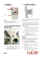
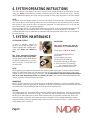
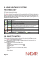
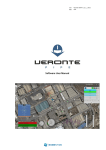
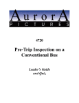
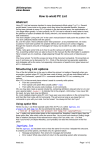
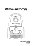
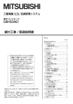
User Manual Central Vacuum System Model Number: NADAIR-CondoVac550 www.NadairVac.com Index 1. Important safety instructions............................................................................................. 3 2. General guidelines and references....................................................................................4 -Grounding requirements -General guidelines to be respected at all times 3. Models...............................................................................................................................5 4. Installation..........................................................................................................................5 Power Unit 5. Low voltage system................... ..........................................................................................5 Installation instructions 6. System operation instruction.............................................................................................6 7. System maintenance.........................................................................................................6 Filtration system Motor 8. Troubleshooting.............................................. ........................................................................7 General 9 . Low voltage system...........................................................................................................8 LED Interpretation chart 10. Safety notes......................................................................................................................8 11. Nadair’s warranty.............................................................................................................9 Page 2 1. Important instructions related to safety CAREFULLY READ ALL OF THESE INSTRUCTIONS PRIOR TO USE THIS CENTRAL VACUUM SYSTEM When using an electrical appliance, it is necessary to obey certain basic precautions WARNING - TO REDUCE THE RISK OF FIRE, ELECTRIC SHOCK OR INJURY: - Unplug the power cord from electrical outlet before making any power unit maintenance. - Do not install outdoors, protect against weathering and do not use on wet surfaces. - This appliance must not be used as if it is a toy. It is therefore necessary to be very prudent when the system is used by children or when in use in the proximity of a child or infant. - This system must be used in conformity with the instructions provided in this manual. Only use the accessories recommended by the manufacturer. - Do not use the system if the power cord or if the electrical outlet are damaged, if the system does not function normally, if it was dropped, was left outdoors in bad weather for an extended period of time or if it was immersed in liquid, the power unit must be sent to an authorized service center. - Do not use the power cord to pull or lift the power unit, nor use it like a handle. Be careful not to pinch it in a door, do not let it hang on a sharp corner or edge. - Examine the openings for foreign objects which may have remained in the pipe. If any, remove the obstructing objects to ensure maximum airflow. - Keep the power cord from any contact with any warm objects or surfaces. - Do not unplug the power cord by pulling on it, always remove directly at the electrical oulet. - Do not use the system or its accessories with wet hands. - Keep hair, clothing, fingers, any other body parts or other objects out of or away from any openings or moving parts of the system. - All functions of the system must be deactivated prior to removing the power cord from the electrical socket. - Take the necessary precautions when using the system on stairs. - Do not use the system to pick up flamable liquids or fuels (i.e. gasoline), nor use the system in areas where such liquids may be present. - Only plug in the power cord into properly grounded electrical socket. For more information on this subject, please see ‘’Grounding specifications’’ in section 2. - The exhaust of the power unit must not give right against a wall, a ceiling or inside a closed space inside a building or structure. It is recommended that the exhaust be vented outdoors. - Do not pick up hot ashes, red ambers, smoking hot material, incandescent material, cigarette butts, matches etc... - Do not put anything on top of the power unit or near it, this could cause the unit to overheat. - DO NOT use the power unit if the pipe network is clogged, this will cause the unit to overheat. KEEP THESE INSTRUCTIONS IN A SAFE PLACE THIS POWER UNIT IS FOR DOMESTIC USE ONLY Page 3 2. GENERAL DIRECTIVES AND REFERENCES ELECTRICAL GROUNDING SPECIFICATIONS The system’s power unit must absolutely be grounded. In the event of a malfunction or a power unit failure, the grounding provides the path of least resistance to any electrical current, minimizing the risk of electric shock. The power unit’s power cord has a length of 65’’ (1,65m) and is fitted with a grounding wire and grounding pin. The power unit‘s power cord must always be directly plugged into a suitable electrical outlet which is itself properly installed and properly grounded, in comformity with the current local electrical standards. Do not use extension cord(s) to connect the power unit to the electrical outlet. WARNING IMPORTANT Improper connection of the power unit grounding wire can result in the risk of electric shock. If you are in doubt of a proper grounding, contact a professionnal electrician. Do not modify the power cord supplied with this power unit. If this power cord connector does not fit your electrical outlet, have the proper electrical outlet installed by a professionnal electrician. This power unit is designed to be used on a nominal electrical circuit of 15 A. 110-120 VAC in 60 Hz. The power cord is fitted with a grounding pin. Make certain that the power cord is plugged into an electrical outlet having the same specifications. This appliance should be used without an adaptor. This power unit should be installed on its own independant circuit and breaker. The manufacturer shall not be held responsible for damages cause by the innapropriate use of this system. The warranty does not cover the damages caused by an innapropriate use of this system nor the problems resulting from an installation which does not meet the specifications, nor any structural or functional alterations made to the power unit. An innapropriate, not-recommended installation of the system or the power unit made without respecting the directives of this document will equally be considered as misuse. All conditions and restrictions are set forth in the limited warranty and in the user manual. To optimize the performances and the life of your Nadair power unit, it is important to do regular maintenance and cleaning of the filter according to the guidelines listed in this user manual. General guidelines to be respected at all time 1. A disposable bag (FD-12.5L-NAD) MUST be in place in the power unit at all times prior to using the system. 2. The power unit must be installed in a well ventilated area, protected from weathering and away from all sources of heat. 3. This central vacuum system is design for dry surfaces only and must not be used on wet surfaces nor be used in any circumstances to pick up liquids or to clean wet carpets or any wet ground. 4. The permanent secondary filter must always lay flat over the motor intake during operation of the system. 5. The motor housing must never be obstructed in anyway to prevent damaging or overheating. 6. Do not use this system to pick up mud or similar substances. Do not vacuum baking flower, talcum powder, cement or gypsum dust, otherwise the motor will overheat and may be damaged and some fine dust will be exhausted outside of the power unit. 7. Do not attempt to shorten or modify the power cord in any way. 8. As a safety measure, unplug the power cord prior to proceed to maintenance or servicing. 9. In order for the warranty to remain valid; any repairs or servicing on the power unit must only be performed by an authorized service center. 10. The position of the power unit must be so, that the power cord and electrical outlet are always easily acessible. 11. Pertaining to the use of an electrified valve (110 VAC) (intended for the connection of a current carrying hose and electrically motorised brush): -Only connect a current carrying hose to this wall valve -Do not install a current carrying valve outdoors -Do not use a damaged hose, bring in the hose for repair at an authorized service center. Page 4 3. MODELS 4. INSTALLATION Mounting Height 36’’ (90cm) NOTE APPLICABLE TO ALL POWER UNIT MODELS: In order to avoid overheating, we recommend that 12’’ (30cm) of clearance be kept all around the power unit. 5. LOW VOLTAGE SYSTEM INSTALLATION Prior to connect the low voltage wires, make certain that the power cord is unplugged from the electrical outlet. The power unit must be installed in a well ventilated area, away from weathering, it must be easilly accessible and away frrom any heat source. The power unit must be installed near an adequate electrical outlet. 1. Determine the power unit location on the wall; we recommend that the power unit be hung at approximately 36’’ (90cm) off the ground so that the debris container is easilly accessible. Allow at least 12’’ (30cm) of clearance all aorund the power unit. If at all possible, you may mount the unit directly onto a concrete wall as to minimize the transmission of vibrations into the building. 2. Installation on a gypsum wall (Gyprock): -Prepare the wall by installing a plywood mounting board (not provided) of 16’’ (40cm) high and 0,75’’ (2cm) thick wide enough to be screwed to at least 2 studs. -Drill three (3), 3/8’’ (10mm) holes with a wood drill bit. Insert the supplied rubber inserts. Fasten the steel mounting bracket with the supplied screws. 3. Installation on a concrete wall: - Drill three (3), 3/8’’ (10mm) holes with a concrete drill bit. - Insert the supplied rubber inserts. - Fasten the steel mounting bracket with the supplied screws. NOTE: You may also elect to install a plywood mounting board on the concrete wall. IMPORTANT Always use the supplied screws and rubber inserts or the appropriate ones for the material you are working with ( Wood, Steel, Brick etc.). 1. First, strip the conductors of the low voltage wire for about 3/8`` (10mm). 2. Insert the conductors of the low voltage wire in the terminals while simultaneously pushing on their respective button as in «a». Give a light pull to the wire to make certain that it is well secured in the terminal. 3. To remove the conductors out of the terminals, lightly push the button as you are imultaneously gently pulling the wires out. Page 5 4. Mount the power unit onto the installed wall mounting bracket. 5. Connect the top air and debris intake pipe to the PVC pipe network by using a flexible pipe and collars (Not-included) (DO NOT GLUE!). 6. Connect the low voltage wire to the terminals on the side of the power unit (as shown in section 5). 7. Verify that the permanent filter is lying flat in the bottom, the disposable bag is in place and that the debris compartment cover is properly seated on top of the power unit. 8. Plug in the unit‘s power cord into the electrical outlet. 9. Install a muffler (optional) to the lower clean air exhaust pipe circuit by using a flexible pipe and collars (optional) (DO NOT GLUE!). (you may elect to vent to the outside with the help of a vent cap (optional). 6. SYSTEM OPERATING INSTRUCTIONS Your new system is now ready to be used. Here are a few simple guidelines to follow when you are using your Nadair Central Vacuum System: Insert the wall end of the hose into one of the vacuum valves installed throughout your home, and you are ready to start, press the switch on the hose handle! NOTE In regards to the low voltage system: All vacuum inlet valves are fitted with two (2) springloaded metal pins (see inside the valve opening). When the two (2) metal parts of the hose wall end are in contact with the two (2) pins inside the valve, the system is energized. You may now turn it on or off from the hose handle switch (if this option was selected). The low voltage cable is connected in parrallel from every valve, it runs all along the pipe network and brings the power to the the remote switch so to remotely start or stop the power unit in all safety. A standard flexible hose, not fitted with an interruptor, will start the power unit as soon as it is inserted in the valve opening. 7. SYSTEM MAINTENANCE FILTRATION SYSTEM In order to maintain optimal air quality in your home, the power unit comes supplied with a 12,5L disposable bag. Never use without a bag. The lower permanent protective filter must be in place at all times, the filter must lay flat on the bottom of the debris compartment just so as to insure no fly-by of large debris into the motor fans. IMPORTANT This Nadair power unit must be used with a 12,5L disposable bag. 3 bags pack #: FD-12.5L-3NAD The disposable bag installs as shown here : 1-Lift the debris area cover. 2-Remove the dirt filled bag. 3-Install the new bag by twisting it. 4- Verify and clean (if necessary) the permanent bottom filter. 5- Replace the debris area cover. NOTE When replacing the disposable bag, make sure that the rubber diaphragm is correctly installed onto the intake PVC pipe fitting. Make sure that the bag is not cut or damaged. Make sure that the cover is well seated in place prior to restarting the power unit. It is recommended to replace the disposable bag as well as to clean the permanent filter 3 or 4 times per year. If the system is used more frequently than normal, repeat the above procedure more often. IMPORTANT NEVER USE this system to pick up liquids, mud or combustible materials. Do not vacuum baking flower, talcum powder, cement or gypsum dust, otherwise the power unit performances will be affected, the motor will overheat and may be damaged and fine particles will be exhausted out. MOTOR This Nadair power unit is equipped with a soft-start controler and a delayed stop. A warning is automatically programmed after 500 hours of usage. The inspection and the maintenance of this appliance must be done in an authorized service center. A Mini-breaker shall cutt-off power to protect the motor in the event of a power surge which may cause the motor to overheat. The low voltage technology system communicates the power unit status through a muticolor LED on the side of the unit. Please consult the interpretation chart in section 8. Page 6 8. TROUBLESHOOTING GENERAL The following may cause failure of the power unit: - Inadequate electrical power (Voltage or Amperage), verify that the electrical power supplied complies with the power unit’s requirement. or; - Abnormal performances of the electronic control module or the motor Before calling a service technician, in case of a malfunction, please review the following situations by running the following simple diagnostics: SITUATION THE POWER UNIT DOES NOT OPERATE VERIFICATION SITUATION LOW OR NO SUCTION OR AIR FLOW AT ALL VERIFICATION Page 7 Verify that there is power in the electrical outlet. Verify the breaker or the fuse in the electrical panel. Verify that the power cord is adequately plugged in the electrical outlet. Verify that the mini-breaker button on the side of the unit is pushed-in. Short-circuit the low voltage connections on the side of the power unit. If the power unit starts, the problem is somewhere else in the valve network wiring or on the current carrying hose. Verify that all low voltage connections are adequate at every valve location. Open every valve, one at a time, and make contact between the two (2) small pins with a metal object. If all the valves work properly, take a look at the low voltage circuit or switch on the hose. If the power unit still does not work after the above diagnostic, bring the unit to the nearest authorized service center. Verify the cleaning tool or the hose for possible obstruction. If the hose is obstructed, try to “massage” the clog out. Try to “reverse” the hose by inserting the cleaning end of the hose in the wall valve and making contact with the two (2) small metal contact pins, hold your hand around the opening for air tightness. Verify if the disposable bag is full, if so replace disposable bag and/or that the filter may be clogged, if so clean the permanent filter. Verify if the debris area cover is adequately placed on the unit for air leaks. Verify that all other valves are shut and that there is no air leaks. If one of the vacuum valves has noticeably less power than the others, it is a sign of a clog at this particular valve. Write a different number on a few paper tissues and pick one up in every valve in the home; see in the debris canister which one is missing so to find which valve is obstructed If none of the valves function properly and that the power unit is running; unhook the flexible pipe on the top of the power unit from the debris intake line. If you have plenty of power there, it is a sign that the clog is between the last valve and the power unit. If the power unit still does not work after the above diagnostic, bring the unit to the nearest authorized service center. 9. LOW VOLTAGE SYSTEM TECHNOLOGY LED status interpretation guide This Nadair Central Vacuum Power Unit is provided with an LED status indicator to keep you informed on the different states and functions during its operation. Reading the following table will allow you to identify the status of your appliance by the different behaviors of the LED. Status Color OFF GREEN Legend The power unit is operational Stop the system, replace bag if needed. (15 hrs reminder). GREEN Reboot while holding the small button for 5 seconds. Arrêter le système, remplacer le sac. No reboot required. ORANGE The power unit is operational. ORANGE Inspection is now required. Stop the system and have service made by a technician RED at an authorized cervice center. GREEN Slow blinking LED Fast blinking LED Solid LED 10. SAFETY NOTES -Make certain that the work area is safe and clear prior to installing your new Nadair Central Vacuum Power Unit. -Wear the necessary safety clothing & equipment prior to start any work i.e.: goggles, gloves etc. -Use the right tools & in good working order: - Hammer - Phillips head screwdriver (cruciform) - Measuring tape - Level - Drill; with wood or concrete bit de 3/8’’ (10mm) - Pliers - Wire stripper Page 8