1
HEALTHCARE PRODUCTS ,w.
1720 SUBLETTEAVE,
ST.LOUIS, WO, 63110
TEL.
(314)771-2400, FAX; (314)771-3465
L90900S-224
REV. A
TABLE O F CONTENTS
Section
P a g e Njimber
INTRODUCTION
GENERAL DESCRIPTION
^
USE O F THE OPERATING M A N U A L
Design
2
Explanation of Warnings/Cautions/Notes
PERFORMANCE CHARACTERISTICS A N D FEATURES
3
PATIENT V A L V E ASSEMBLY
Visual Indicator
Pressure Limit Alarm Module
Source G a s Inlets
Exhalation Valve
3
CONTROL MODULE
Source G a s Inlet
Patient Valve Outlets
Breaths Per Minute (BPM)
Tidal Volume (Vf)
Inspiratory Time {Til
Patient Valve Supply Tubing and Oxygen Line
Non-Rebreathing Vglve and Corrugated Hose
^
U N P A C K I N G A N D INSPECTION O F THE
AUTOVENT 2 0 0 0 / 3 0 0 0
8
OPERATING INSTRUCTIONS
Instructions for Use of the AutoVent 2 0 0 0 / 3 0 0 0
v/ith Oxygen Cylinders
Regulator Attachment
Control Module Attachment
Instructions for Use of the AutoVent 2 0 0 0 / 3 0 0 0
with a W a l l Outlet Employing a Quick Connection Adapter
Instructions for use of the AutoVent 2 0 0 0 / 3 0 0 0
with an A i r / O x y g e n Blender
Ventilator Check out
8
PATIENT USE
12
MAINTENANCE OF THE LSP AUTOVENT 2 0 0 0 / 3 0 0 0
Cleaning and Disinfecting Equipment
Cleaning and Disinfecting the Control Module
Cleaning and Disinfecting the Patient Valve Assembly
Cleaning the Non-Rebreathing Valve
14
STORAGE O F THE LSP AUTOVENT 2 0 0 0 / 3 0 0 0
16
TROUBLESHOOTING GUIDE FOR THE
LSP AUTOVENT 2 0 0 0 / 3 0 0 0
16
W A R R A N T Y INFORMATION
18
APPENDIX
20
A:
B:
C:
D:
E:
F:
Support Equipment
Patient Valve Specifications
Control Module Specifications
Oxygen Pressure Regulator Specifications
AutoVent 2 0 0 0 / 3 0 0 0 Altitude Conversion Chart
AutoVent 2 0 0 0 / 3 0 0 0 Oxygen Cylinder Depletion Chart
1
INTRODUCTION
Long an innovator in
emergency and trauma
medicine, Life Support
Products has been a
primary manufacturer of
oxygen delivery devices for
\field use in the Uniled
States and v/orldwide since
1979. LSP is also a
manufacturer of a wide
range of trouma, burn and
rescue devices.
Specifications for the
LSP AutoVent 2 0 0 0 / 3 0 0 0 ,
including the Patient Valve
Assembly, Control Module,
and Regulators intended
for use with this device, ore
included in the Appendix
of this manual.
The Life Support Products
AutoVent 2 0 0 0 / 3 0 0 0
represent a major
breakthrough in pneumatic-
technology. Theyare
inlended for the ventilatory
ossistance of patients
following cardiac arrest,
near drowning, trauma,
paramedical transport, and
other circumstances
requiring ventilatory
assistance.
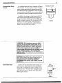
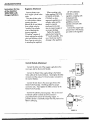
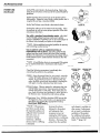
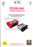
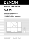
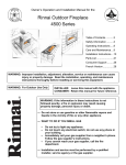
THE AUTOVENT
2000/3000
GENERAL
DESCRIPTION
The LSP Automatic
Ventilator (AutoVent
2 0 0 0 / 3 0 0 0 ) time-cycled,
constant-flow, gas-powered
ventiialors offer controlled
ventilation at rales from 8
to 15 breaths per minute
(BPM) in the AutoVent
2 0 0 0 version, and 8 to 2 0
breaths per minute in lhe
AutoVent 3 0 0 0 version.
The attached Patient Valve
Assembly allows a patient
to draw supplemental gas
flow (up to 36 LPM) with
spontaneous effort.
Designed for transport and
emergency medical use,
the AutoVent 2 0 0 0 delivers
from 4 0 0 ml to 1 2 0 0 ml
volume. The AutoVent
3 0 0 0 delivers from 2 0 0 to
1200 ml in volume.
Both AutoVents deliver
Peak Pressure up
to 60 ±5 cm H 2 O at
flow rates from 12 to 3 6
liters per minute (LPM).
They ore small, c o m p a c t
units ideally suited for
emergency a n d transport
situations at temperature
extremes from 0°F to
125°F. O p e r a t i n g
p o w e r is o b t a i n e d from
standard 5 0 psi source
g a s . They are simple to
assemble a n d operate,
a n d their functions are
easily understood. The
Ventilators meet or
e x c e e d the A m e r i c a n
Heart A s s o c i a t i o n ( A H A )
guidelines for
resuscitation.
A n A u d i b l e alarm
sounds whenever
ventilatory pressures
a p p r o a c h the preset
pressure limit, alerting
the operator.
This
alarm will continue to
sound until the a i r w a y
pressure drops or the
system cycles to the
expiratory p h a s e .
W A R N I N G : Use only
O S directed. Improper
usage or unauthorized
modification of this
product m a y result in
user or patient injury.
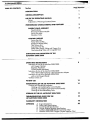
FIGURE 1. A U T O V E N T 2 0 0 0 / 3 0 0 0
USE OF THE
OPERATING MANUAL
This operaUng manual for the Life Support Products
AutoVent 2 0 0 0 / 3 0 0 0 Automatic Ventilators has been
designed for ease of use in the paramedical and field
transport setting.
Design
Illusfrations are provided throughout this manual to
provide the user with both a graphic and narrative
description of the ventilators' operating features.
Explanation of
Warnings/Caul
Notes
tions/
This operoting manual contains three (3) types of
statements with which the user should be aware, and are
defined as followings:
W A R N I N G : Potential injury to the patient or
operator. These are a l w a y s in boxes throughout
the text of the manual.
CAUTION: Potential d a m a g e to the ventilator,
breathing circuit, a n d / o r other equipment may
result. These are a l w a y s in brackets throughout
the text of the m a n u a l .
**NOTE: An item of special interest concerning the use
and operation of tbe device(s) or feature (s) being discussed
is high-lighted to nofe ease of use or understanding. These
are always preceded and followed by asterisks throughout
the text of fhe manuai * *
WARNINGS AND CAUTIONS SHOULD BE READ PRIOR
TO OPERATING THE LSP AUTOVENT 2000/3000.
3
PERFORMANCE
CHARACTERISTICS
A N D FEATURES
PATIENT VALVE
ASSEMBLY
The AutoVent 2 0 0 0 / 3 0 0 0 are time cycled, constant
^ l " ^ ^ ' 9°^ powered ventilators. This feature allows the
ventilators' automatic rate to be set by the operator from 8
to 15 breaths per minute (BPM), in the AutoVent 2 0 0 0
version, and 8 to 2 0 BPM in the AutoVent 3 0 0 0 version.
Should the patient require additional breaths, these can be
obtained on demand by making an Inspiratory effort on the
patient valve.
The patient valve delivers
both controlled and
spontaneous breaths to the
patient. It consists of a
demand valve, a visual
Indicator, pressure limit
alarm, and exhalation
valve. It has a standard
15mm. inside
diameter/22mm. outside
diameter adopter, which is
compatible with masks and
other airway devices.
The patient valve allows
spontaneous breothing
upon demand if the patient
makes an insplrotory effort
o f - 2 c m . H2O. (The BPM
control may be turned to
the " 0 " position if desired
for this purpose.)
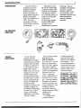
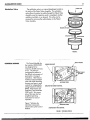
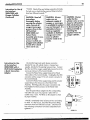
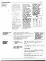
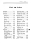
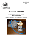
Figure 2 indicates the
individual components
which make up the Patient
Valve Assembly.
**NOTE: Since fhe patient
vaive and control module
are a matched sef wifh
identical serial numbers,
do not separate. If used
wifh other units, setting
may not be accurate. **
VISUAL INDICATOR
^ S O U R C E OAS INLETS
PRESSURE LIMIT A U R M
TOP VIEW
- OUTLET ADAPTER
(EXHAUTION VALVE INSIDE)
SIDE VIEW
Visual Indicator
FIGURE 2.
PATIENT V A L V E A S S E M B L Y
The visual indicator is located on the top of the Patient
Valve Assembly. This indicator displays bright green as
gas flows during Inspiration. During expiration, the
indicator dome is clear. The visual indicator does not
indicate on spontaneous breaths.
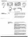
VISUAL INDICATOR
i4utoVent20C=0/300C=
Pressure Limit A l a r m
Module
An audible pressure limif alarm is located in the Patient
Valve Assembly. This alarm sounds v/henever the patient
airv/ay pressure approaches the designed pressure limit.
The Pressure Limit Alarm v/ill p'phfmue to sound during the
inspiratory phase until either the airway pressure decreases
or the ventilator cycles off to begin the expiratory phase.
In addition to functioning as a high pressure alarm the
alarm module also provides additional air entroinment
during the Intermittent Mandatory Ventilation (IMV} mode
should the patient's inspiratory flow rote exceed the flow
delivery from the control module. The entroinment of
ambient air occurs through the blue rubber diaphragm
located on the side of the alarm module.
PRESSURE LIMIT A L A R M
FIGURE 4.
W A R N I N G : If t h e i h a x i m u m pressure limit is
reached/ the pre-set tidal v o l u m e m a y not be
delivered to the patient. Inspiratory time will
remain constant, h o w e v e r , a n d a n inspiratory
hold will be maintained with no additional
volume being delivered until the venfilator cycles
to the expiratory phase. This waming
also
appears under Tidal Volume in the
Performance
Characterisfics,
W A R N I N G : Should the blue rubber d i a p h r a g m
b l o w o u t w a r d from the a l a r m module's air
entroinment ports, remove the AutoVent
immediately from service, a n d contact y o u r LSP
distributor.
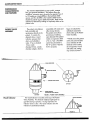
Source G a s Inlets
Located on the side of the Patient Volve Assembly the
inlets connect the Patient Valve with the Control Module.
The top inlet: (1) Supplies the actuator assembly and is a
nippled connector. The bottom inlet; (2) Supplies source
gas to the patient and is a diameter index safety system
(DISS) oxygen connector.
FIGURE 5 .
5
Exhalation V a l v e
The exhalation valve is on internal diaphragm locoted.on
the inside of the Patient Valve Assembly. The exhalation
valve allov/s the patient to exhale through the Patient Valve
Assembly once the inspiratory cycle is completed, whether
ventilator-controlled, or on demand. This valve can be
accessed by removing the outlet adopter on the Patient
Valve Assembly.
PRESSURE LIMIT ALARM
FIGURE 6.
CONTROL MODULE
_ )
The Control Modules for
the AutoVent 2 0 0 0 / 3 0 0 0
are designed to be
compact, durable ond easy
to use. The units are
constructed to perform in
the difficult environments of
paramedic or transport
operations. Their features
include an impact-resistant
case with shock absorbing
bumpers and easy to read
controls for independently
setting Breaths Per Minute
(BPM), Tidal Volume and
Inspiratory Time (AutoVent
3 0 0 0 only). The reverse
side of the case also has
simplified operating
instructions for ease of
operation.
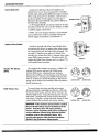
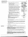
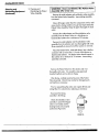
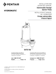
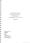
Figure 7 indicotes the
individual components
which make up the Control
Module.
, TIDAL V O L U M E
SOURCE G A S INLET
PATIENT V A L V E
OUTLETS
>
AUTOVENT 2000
BREATHS PER MINUTE C O N T R O L
^AUTOVENT 3 0 0 0
INSPIRATORY TIME C O N T R O L
FIGURE 7. C O N T R O L M O D U L E
Source G a s Inlet
Located on the left side of the Control Module and
marked with an arrow, the source gas inlet is a standard
diameter index safety system (DISS) male oxygen connector.
When a high pressure line is attached to a 5 0 psi source
gas from a cylinder or bulk oxygen source, this gas is
delivered to the Control Module and cycled for delivery to
the Patient Valve Assembly.
An Air/Oxygen Blender con also be inserted in line with
this system, between the source and the ventilator, to deliver
a specified oxygen concenfration.
**NOTE: Use ofan Oxygen Analyzer is recommended
prior to patient use in order to accurately measure the
desired oxygen concentration fo be delivered. **
SOURCE G A S INLET
FIGURE 8,
Patient V a l v e Outlets
Located on the right side of the Control Module body
and marked with arrows, the patient valve outlets connect
the Control Module with the Patient Valve Assembly. The
top outlet (1) Supplies source gas to the Patient Valve
Assembly at a constant flow dnd is a diameter index safety
system (DISS) oxygen connector. The boftom outlet: (2}
Supplies the Patient Valve Actuator and is a unique 7 / 1 6
inch threaded female connector.
Breaths Per Minute
(BPM)
Tidal V o l u m e (VO
This control sets the ventilator rate from 8 to 15 BPM In the
AutoVent 2000 version, and from 8 to 20 BPM in the
AutoVent 3000 version. Adjusting the knob clockwise
decreases the breathing rate and adjusting counter clockwise
increases the rate. Source gas is available on demand, even
in the " 0 " position up to 36 LPM depending on Tidal Volume
setting, from the Patient Valve Assembly to allow the patient to
breathe spontaneously.
This control adjusts the volume available to the patient
during a breath and is adjustable from 400 ml to 1200 ml in
the AutoVent 2000 version, and from 200 to 1200 mil in the
AutoVent 3000 version. Turning the knob clockwise increases
tidal volume. Turning the knob counter clockwise decreases
tidal volume. Foiiowing a volume adjustment change, the tidal
volume stabilizes after one breath and remains constant.
WARNING; If the maximum pressure limit is reached,
the pre-set tidal volume may not be delivered to the
patient. Inspiratory time will remain constant,
however, and an inspiratory hold will be maintained
with no additional volume being delivered until the
ventilator cycles to the expiratory phase. Ihis
warning also appears under Pressure Limit Alarm
Module in the Performance Characteristics.
FIGURE 9 .
FIGURE
AUTOVENT 2000
10.
AUTOVENT 3000
FIGURE 11.
AUTOVENT 2000
AUTOVENT 3000
Tidal V o l u m e (Vf)
(Continued)
* *NOTE: It is recommended that you periodically check the performance characteristics of
fhe AutoVent 2000/3000
during maintenance by placing a pressure manometer in line
with fhe patient circuit near fhe outlet to verify inspiratory pressures and the accuracy of the
pressure alarm limit. **
Inspiratoiy Time (Ti)
This control knob in the center position of the AutoVent 3000
allows adjustment of the potient's inspiratory time. The two
settings allow selection of Adult and Child inspiratory time
respectively. The inspiratory time for the circled orange child
setting is approximately 1 second and when selected corresponds
to the circled orange settings on the BPM and Tidal Volume
control knobs. The inspiratory time for the white Adult setting is
approximately 2 seconds and when selected corresponds to the
FIGURE t i A .
white settings on the BPM and Tidal Volume contro! knobs. The
AutoVent 2000 has a pre-set inspiratory time of approximately 2
seconds.
CAUTION: W h e n you select either .Adult or Child Setting, rotate the
center control knob to the appropriate setting a n d position it against
either of the end stops.
W A R N I N G : Should the inspiratory time control k n o b on the AutoVent
3 0 0 0 be adjusted after initial setup, it will alter the patient's B P M a n d
Tidal V o l u m e settings.
Patient V a l v e Supply
Tubing a n d O x y g e n
Line
The patient valve supply tubing is a specially
constructed twin polyurethane hose enclosed in a
PVC jacket. It Is three feet in length and has one
portion with DISS fittings at both ends while the
other section is designed for nipple connection at
one end and for connection to the unique 7 / 1 6
inch female connector (on the Control Module) at
the other end. The oxygen line is standard oxygen
tubing with DISS fittings at both ends.
OXYGEN LINE
PATIENT VALVE SUPPLY TUBING
FIGURE
12.
P.E.E.P. PORT
Non-Rebreothing
V a l v e a n d Corrugated
Hose
Part number L496 Non-Rebreathing Valve is
designed to allow a simple method for providing
P.E.E.P. (posltlve-ehd-expiratory-pressure) to a
patient. Attach one end of the corrugated flex tube
to the patient valve assembly. Attach the opposite
end to the inlet port on the P / N L496 (see diagram)
valve. Both these connections are friction fit, so be
sure to slide the flex tube over each connection as
far as possible. At this point, you ore set to install
your P.E.E.P. product in the appropriate port.
W A R N I N G : The P / N L496 Non-rebreathing
valve is not for use in toxic atmospheres
INLET PORT
NON-REBREATHING
VALVE
CORRUGATED HOSE
8
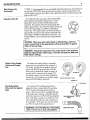
PATIENT V A L V E SUPPLY TUBING
UNPACKING A N D
INSPECTION OF THE
AUTOVENT
2000/3000
CONTROL MODULE
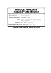
After opening your new LSP AutoVent 2 0 0 0 / 3 0 0 0 ,
examine the shipping carton and contents. Lay out contents
so that each component is identifiable, as displayed below
(Figure 13). If the carton is crushed, previously opened, or
shows ofher signs of damage, notify the carrier immediately
to file a claim. Do not use the unit on a patient until it has
been tested and performs as specified.
The complete LSP AutoVent 2 0 0 0 / 3 0 0 0 , P / N L460, and
AutoVent 3 0 0 0 Automatic Ventiiator, P / N L461, consists of
the following component parts:
- ),
Descnption
One Control Module
One Patient Valve Assy.
One Patient Valve
Supply Tubing
One Oxygen Line
Non-Rebreathing Valve
Corrugated Hose
Operator Manual
A V 2000 Port No.
L462
A V 3000 Part No.
L463
L535114
L535026
L496
L535124-010
L909005-224
L535114
L535026
L496
L535124-010
L909005-224
O X Y G E N LINE
NON-REBREATHING VALVE &
C O R R U G A T E D HOSE
FIGURE 13
**NOTE: Appendix A provides a list of suggested equipment for use in conjunction
with or in support of the LSP AutoVent 2000/3000. * *
PATIENT V A L V E A S S E M B L Y
OPERATING
INSTRUCTIONS
**NOTE: Read all instructions carefully prior to set-up ond
operation ofthis unit. Particular attention should be paid to
all warnings, cautions and notes in order to assure proper
performance during use.**
W A R N I N G : Should a
mechanical problem
develop or the patient
appears to be
experiencing difficulty
while connected to
this unit, disconnect
the unit immediately
and ventilate by other
means. If unable to
determine the cause
of the problem, the
unit should be
returned to a n
authorized AutoVent
repair center.
W A R N I N G : This
device operates with
medical gases under
pressure, including
o x y g e n . Do not use
this device while
smoking or near open
flames. Do not use
oil on this device or
operate near
flammable materials.
W A R N I N G : This
device should only be
operated b y qualified
personnel under
a p p r o v e d medical
direction.
CAUTION: In order to
provide optimal
performance, check
all source gas supplies
to assure only clean,
d r y gas is used, free
of contaminants
a n d / o r liquids.
Xut07ent2OC=O/3OOO
Instructions for Use
of the AutoVent
2 0 0 0 / 3 0 0 0 with
O x y g e n Cylinders
Regulator Attachment
Remove plastic wrap
from oxygen cylinder valve
outlet.
Point the cylinder valve
in a safe direction before
opening the valve.
Remove all dirt and debris
from cylinder valve by
"cracking" the cylinder
prior to attaching the
pressure regulator.
("Crocking" consists of
slowly opening the cylinder
valve and allowing a brief
flow of gos to occur prior
to attaching the regulator).
When mounting a pin_
index regulator (LSP P / N i
L270-020, L270-030,
V
L735-060, or other
approved regulator) on a
cylinder, make sure the
gasket is properly
positioned on the inlet
stem to prevent oxygen or
source gas leakage.
Tighten the regulator
yoke by hand using the
"T" handle assembly. (The
use of tools may result in
damage to the regulator).
LSP P / N L28O-02O,
Ll 60-060, or other
regulators complying with
Compressed Gas
Associafion (CGA)
guidelines, mount on
cylinders with C G A 5 4 0
connections.
Connect the oxygen high
pressure line to fhe 5 0 psig
gas ouflet on the regulator.
Control Module Attachment
Connect the ofher end of fhe oxygen supply line to the
source gas inlet on the Control Module.
Connect the Patient Valve supply tubing to fhe Patient
Valve outlets of the Confrol Module. Hand tighten the DISS
connector and the unique 7 / 1 6 inch actuator connector fo
the Confrol Module.
Connect fhe twin hose to the source gas inlets on the
Patient Valve Assembly. The fittings allow for proper
connecfion only. Hand tighten the DISS connector to the
Patient Valve Assembly.
Examine the cylinder pressure gauge. This can be used
to indicate cylinder contents since the pressure is
proportional to the amount of remaining oxygen. A
portable cylinder is essentially empty when the pressure has
fallen to 2 0 0 psig.
FIGURE 14.
10
Instructions for Use of
the AutoVent
2 0 0 0 / 3 0 0 0 with
O x y g e n Cylinders
(Continued)
Instructions for Use
of the AutoVent
2 0 0 0 / 3 0 0 0 with a
W a l l Outlet Employing
a Quick Connection
Adapter
* *NOTE: Check ail line and tubing connections for leaks.
If a leak occurs, check that the previous fitting instructions
have been followed correctly. **
CAUTION: Read all
instructions
thoroughly before
opening the cylinder
v a l v e . Connect all
oxygen/source gas
pressure lines to the
LSP AutoVent
2000/3000 and
Patient V a l v e
Assembly prior to use.
Assure all high
pressure outlets ore
plugged and cylinders
turned off or closed
w h e n not in use.
CAUTION: A l w a y s
m a k e sure a n
adequate supply of
o x y g e n or source gas
is available for patient
use a n d transport. It is
advisable to have a
back-up regulator
available to facilitate
change-over in the
event a cylinder
transfer needs to be
made.
CAUTION: A l w a y s
verify that the
cylinder valve is in the
closed or off position
(fully clockwise) prior
tb disconnecting the
tubing assembly or
removing the
regulator from the
o x y g e n cylinder.
Use standard approved quick release connectors
intended for use with cylinder banks or transport gas
supplies, attached to 5 0 psig high pressure lines. Connect
the other end of the oxygen supply high pressure line to the
source gos inlet port of the Control Module.
Connect the Patient Valve supply tubing to the Patient
Valve outlets of the Control Module. Hand-tighten the DISS
connector and the unique 7 / 1 6 inch actuator connector to
the Control Module.
Connect the Patient Valve supply tubing and the actuator
supply tubing to fhe inlet ports on fhe Patient Valve
Assembly. The fittings allow for proper connection only.
Hand tighten fhe DISS connector to the Patient Valve
Assembly.
Insert the quick-release adapter into the corresponding
wall outlet and assure it is properly in place with an
audible snap or click. Pull firmly on the adapter to check
its proper insertion.
— JrTTT—
**NOTE: Immediately check all pressure lines and tubing
for leaks. If a leak occurs, check thaf fhe previous fitting
insfructions have been followed correctly. Check thaf all
line and tubing connections have been adequately hand
tightened.**
FIGURE
15.
Insfructions for Use of
the AutoVent
2 0 0 0 / 3 0 0 0 with a n
A i r / O x y g e n Blender
Instructions for this apphcation ore essentially identical to
those for use wifh either cylinder or wall outlet systems.
The high-flow blender system should be connected to the
source gases as per manufacturers instructions. The
blender then becomes the attachment site for the source
gas supply line to the Control Module.
CAUTION: Always follow the blender
manufacturer's instructions/ contained in the
blender product m a n u a l , for exact connection of
the blender to cylinders or w a l l sources. A l w a y s
use a high'flow
blender (15 LPM to 150 LPM) for
ventilatory application.
* *NOTE: Make sure a compressed air source and oxygen
source are available prior to using a blender.**
Connect the other end of the oxygen supply high
pressure line (source gas supply line) to the source gas inlet
port of the Control Module.
Connect the Patient Valve supply tubing fo the Patient
Valve outlets of the Control Module. Hand-tighten the DISS
connector and the unique 7 / 1 6 inch actuator connector to
the Control Module.
Connect the Patient Valve supply tubing and the actuator
supply tubing to the inlet ports on the Patient Valve
Assembly. The fittings allow for proper connection only.
Hand tighten the DISS connector to the Patient Valve
Assembly.
**NOTE: Immediately check all pressure lines and tubing
for leaks. Ifo leak occurs, check that the previous fitting
instructions have been followed correctly. Check that all
line and tubing connections have been adequately hand
tightened.**
* *NOTE: Assure the delivery of precise oxygen
concentrations when using a blender by inserting an
oxygen monitor probe in the gas delivery system at the
patient valve ouflet prior to patient use. * *
W A R N I N G : A l w a y s check or change the source
g a s e s if a l o w pressure blender a l a r m sounds,
distinguished b y a continuous high-pitched h u m .
i4utoVent2000/300C=
Ventilator Check-Out
12
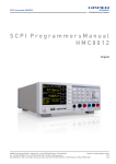
1. Check the ventilator system for proper function by
performing the following tests:
>
• Set the BPM control knob to the setting marked " 1 2 " .
(Adult for AutoVent 3000)
• Set the Tidal Volume (Vt) control knob to 8 0 0 ml.
• Set the Inspiratory Time control knob to the adult setting
on the AutoVent 3 0 0 0 , (Inspiratory time is pre-set on
the AutoVent 2 0 0 0 ) . Rotate the control knob clockwise
until it is against the end stop on the adult setting.
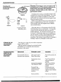
• Count the number of complete ventilator cycles for a
fuil minute., At the checkout setting, there should be 12
BPM delivered, with a 2 second inspiration and 3
second expiration per breath.
^ClO >
FIGURE 1 6 .
60 SECONDS
I N S P I R A T O R Y TIME
2 SEC.
12 B P M
E X P I R A T O R Y TIME
3 SEC.
2. Occlude the outlet of the patient Valve Assembly. An
audible pressure limit alarm should sound after the
ventilator cycles, indicating the designed pressure limit
has been reached.
**NOTE: The pressure limit alarm should sourid
throughout the latter portion of the breath after reaching fhe
pressure limif, and stop when the ventilator cycles to
expiration.**
**NOTE: AutoVents & patient Valves are serialized and
calibrated to work together and sfiould remain
together for the life of the products
FIGURE 1 7 .
FIGURE
18.
3. Test the unit for proper function prior to each patient use. Refer to Maintenance section
for this procedure (page 14).
4. Should the unit fail to operate properly at any time, refer to the Troubleshooting Guide
(page 16.) Disconnect the patient from the ventilator any time the unit does not appear
to be operating properly. Ir unable to determine the cause of problem, contact Ufe
Support Products for service.
5. Clean the unit after each use (refer to the Maintenance section for detailed instructions
on page 14).
6. Always store the unit in a clean, dry place.
PATIENT USE
**NOTE: ifthe LSP Automatic Ventilator is to be powered by a cylinder, be sure to turn on
the cylinder valve slowly. **
W A R N I N G : This device should only be operated b y qualified personnel
under a p p r o v e d medical direction.
Check for obstructions in the patient's throat or mouth (vomitus, foreign bodies, broken
dentures, etc.), and remove if present, in occordance with prevailing standards.
Set fhe volume to equal 8 to 10 ml. for every kg. of body weight; e.g., 7 0 kg. patient
equal 7 0 0 ml. volume.
W A R N I N G : The AutoVent 3 0 0 0 is not recommended for use with patients
less than 20 k g . The AutoVent 2 0 0 0 is not recommended for use with
patient less than 4 0 k g .
13
PATIENT USE
(Continued)
Set the BPM control knob to the desired setting. Refer to the
quick set-up insfructions on the bock of the Control Module for
guidelines.
Set the inspiratory time control knob to the desired adult or
child position. Rotate the control knob to either position unfil it
is against the end stop. (AutoVent 3000)
Set the Tidal Volume control knob to the desired volume.
FIGURE 19.
Occlude the outlet port of fhe Potient Valve Assembly. Allow
the ventilator to cycle fo ensure proper operation of the valve
and pressure limit alarm.
Use with a standard resuscitation mask: of/er initial
Control Module settings have been mode and a patient
airway is established, install the mask on the outlet adopter of
the Patient Valve Assembly and place on the patient.
FIGURE 2 0 .
* *NOTE: Follow established procedural guidelines for opening
and maintaining a patient ain,vay.**
Use on patients with on endotracheal tube or
tracheostomy tube in place: after initial control Module
settings have been made, connect the Patient Vdlve Assembly
directly to the endotracheal or tracheostomy tube adapter (15mm.
inside diameter/22mm. outside diameter aimensions allow this
connection).
**NOTE: A humidification device is recommended ifthe patient
has an endoctracheai iube or tracheostomy tube in place.**
Check the following parameters immediately after
connecting the patient to the ventilator.
FIGURE 2 t .
AUTOVENT 2000
FIGURE 22.
AUTOVENT 3000
FIGURE 23.
(1) BPM - Usina fhe second hand on your watch, count the
number of breaths delivered to the patient for one full
minute. Ifyou need to increase or decrease fhe rate,
adjust the BPM confrol knob accordingly, checking the
rote again once the adjustment has been mode.
(2) Tidal Volume - Observe patient for adequate chest rise
and fall (chest excursion . Chest excursion should be
normal and equal on both sides. If the chest does not
rise, check the airway and evaluate for other injuries to
the thoracic area. Recheck the tidal volume setting.
(3) Inspiratory Time - With the AutoVent 3 0 0 0 ensure that
the Inspiratory Time control knob is set appropriately
and al the way against the appropriate end stop.
(AutoVent 3 0 0 0 only.)
**NOTE: If fhe pressure
limit alarm sounds during
the inspiratory phase and
adequate chest movement
does not occur, an
increase in airway
resistance, a blocked
airway and/or a stiff lung
is indicated.
Increase the volume
deiivered to the patient,
until adequate chest
movement occurs, by"
rotating the Tidal Volume
control knob in a clockwise
direction. Disconnect the
patient from the ventilator
and attempt to ventilate via
other means if adjustments
do not result in satisfactory
ventilation ofthe patient.
For additional information,
refer to fhe Troubleshooting
Guide. * * (page 16)
14
PATIENT USE
(Continued)
If the patient is being
ventilated by mask, check
the patient frequently for
signs of vomiting. Should
vomiting occur, remove the
mask to prevent aspiration
which may cause airway
obstruction.
Immediately clear the
mask and Patient Volve
Assembly of any foreign
material, reestablish the
patient's airway, and
resume ventilation.
**NOTE:
TABLE I.
The ventilator will deliver
100% source gas to the
patient on demand, up to
3 6 LPM depending on the
tidal volume setting (See
Tablet.). Any volume
required by the patient in
excess of the indicated
source gas flow rate (see
Table I.) will be supplied
by ambient air.
when performing
maintenance and cleaning
of patient care equipment. * *
Clean and disinfect the ventilator after each use.
Re-certify calibration
of AutoVent once a
year.**
**Note: AutoVents should be checked
for calibration
annually.
1 . Cleaning and
Disinfecting the Control
Module
**NOTE:
Water will not
affect the operation of the
Control Module. * *
F L O W (LPM)
ADULT
CHILD
400
200
12
600
300
18
800
400
24
1000
500
30
1200
600
36
Source gos flow roles upon patieni tJemord.
Gloves and protective coverings are
recommended
**NOTE:
Cleaning a n d
Disinfecting
Equipment
W A R N I N G : Monitor
the patient closely
while using the
demand m o d e .
Should the patient's
respirations s l o w ,
become shallow o r
labored, return to
initial automatic
viehtilatbr settings
immediately.
TV SEHING
If unable to resume
ventilation with the Patient
Valve Assembly, use a
resuscitator bog or perform
mouth-to-mask
resuscitation.
**NOTE: If a compressed
gas cylinder is used, check
the cylinder contents
frequently; should the
cylinder require
MAINTENANCE OF THE
LSP AUTOVENT
2000/3000
repiacemenf, perform
maneuver with minimal
interruption to ventilation of
the patient. * *
Should patient begin
breathing spontaneously
(an effort of-2 cm.HjO will
activate the demand valve)
it may be desirable to
decrease or turn the
ventilator rate (BPM) to the
" 0 " position. This wiil
allow the patient to breathe
spontaneously.
W A R N I N G : Cleaning
procedures must b e
p e r f o r m e d In a n
environment free of
oil a n d petroleumb a s e d products.
Leave hoses connected so you d o not get water inside.
Follow established protocol regarding frequency of
cleaning.
Do not submerge the Control Module when cleaning. Take
a clean cloth soaked in a detergent solution and wipe off
any residue from surface.
W i p e thoroughly.
Take a clean cloth soaked in an 8 0 % isopropyl alcohol
solution or a cold chemical disinfecting solution, and wipe
entire surface of Control Module.
Rinse Thoroughly being careful not to get any liquid inside
the control module.
Take o clean cloth and dry surface of Control Module.
Test Control Module before use.
15
i4uto7ent2000/3OOC=
Cleaning q n d
Disinfecting Equipment
(Continued)
2. Cleaning and
Disinfecting the Patient
Valve Assembly
W A R N I N G : Clean a n d disinfect the Patient V a l v e
A s s e m b l y after every
use.
Remove the outlet adapter qnd exhalation valve assembly
from the Patient Valve Assembly. Leave tubing assembly
connected.
Clean all foreign matter from the components with a mild
soap solution, being careful not to get any liquid inside the
Patient Valve Assembly. Rinse the parts thoroughly in clean
water.
Immerse the outlet adapter and the exhalation valve
assembly from the Patient Valve in a disinfectant or
bacteriocidal solution for a rr\'m\n)urr\ of 10 minutes.
Remove the outlet adapter and the exhalation valve
assembly from the solution and rinse //loroug/i/y with water.
Rinse repeatedly to assure that all the solution is removed.
Place the Patient Valve, outlet side down, into a shallow
container with not more than 1 / 2 inch of disinfectant or
bacteriocidal solution. The Patient Valve should remain in
this solution for a minimum of 10 minutes. Leave tubing
assembly connected.
Remove the Patient Valve from the solution and rinse
thoroughly with water. Dry assembly using approved
stondord methods such as hot air drying.
After drying, carefully examine the ports of the Patient
Valve Assembly. Discard any cracked or damaged ports
and replace as necessary.
Prior to reassembling the entire unit, inspect all lines and
tubing filters for contaminants, replacing as necessary.
Reconnect the tubing
assembly to the fittings.
Check fhe exhalation valve
assembly to pssure the flapper
valve is not twisted and the
locating bosses are properly
positioned. (Figure 25)
FIGURE
24.
AxiioVent,
16
•>','•
Cleaning a n d
Disinfecting Equipment
(Continued)
LOCATING DRACKEtS
FIGURE
VJ
25.
—
CAUTION: If the flapper valve is twisted or the
locating bosses are not properly positioned, the
Patient V a l v e Assembly will not function
properly. A l w a y s m a k e sure the valve is flat
a n d properly seated.
Immediately after cleaning, reassemble the Patient Valve
Assembly and connect to the Control Module. Turn on the
oxygen supply and allow the ventilator, to cycle several
times to blow out any liquid which may hove gotten inside
during the cleaning process.
Test the unit for proper function prior to each patient use.
Attach an inflatable test lung, P / N L109, to the Patient
Valve Assembly outlet and complete the test at different
rates and tidal volumes.
FIGURE 2 7 .
3. Cleaning ihe NonRebreathing Valve
Clean after each use. All components of the P / N L496
Non-Rebreathing Valve ore autoclavable. To disassemble,
unscrew the valve inlet from the outlet and remove the
duckbill diaphragm. The individual components can now
be cleaned. If autoclaving systems are not available, you
may also sterilize via cidex or other bacteriocidal solution.
Be sure to rinse and dry all parts thoroughly before reassembling. After cleaning, inspect all ports for damage or
breakage. Replace any damaged or broken parts.
STORAGE OF THE
LSP A U T O V E N T
2000/3000
Store the unit in a clean, dry area within a temperature
range of-40°F to 160°F.
After long periods of storage, the unit should be fully
tested before use in accordance with the checkout
procedures in this manual.
TROUBLESHOOTING
GUIDE FOR THE
LSP A U T O V E N T
2000/3000
INDICATION
PROBABLE CAUSE
SOLUTION
Decreased tidal volume or
decreased chest expansion
Leak around mask or
Patient Valve tubing
Check all connections for
leaks
Inappropriate volume
setting
Decreased lung
compliance a n d / o r
increased airway
resistance
Check Control Module
setting and adjust as
required
Check Control Module
setting and adjust as
required
Evaluate patient and
correct as required by
adjusting Control Module
settings
Ain/vay secretions
Clear airway of secretions
Inappropriate inspiratory
Time setting {AV 3000)
17
i4utoVent2C=00/3C=C=0
TROUBLESHOOTING
GUIDE
(Continued)
Volume setting to high
Check Control Module
settings and adjust volume
OS required
Increased lung compliance
Evaluate patient and correct
as required by adjusting
Control Module Settings
Inappropriate inspiratory
Time setting (AV 3000)
Check Control Module
sfetttng"and adjust as
required
Pressure limit olorm at
beginning of inspiratory
phase
Ain//ay blockage, kinked
tubing, and/or increased
airway resistance
Clear airway of secretions
or foreign matter; check
endotracheal tube; check
ventilator tubing
Pressure limit alarm during
inspiratory phase
Increased airway resistance
Evaluate patient and adjust
ventilators as required
Decreased lung compliance
Evaluate patient and correct
as required by adjusting
Control Module settings
Coughing
Attempt to alleviate
coughing
Increased airway secretions
Clear ain//ay secretions
Gos source failure
Change oxygen cylinder if
being used, or evaluate
and check gas source
outlet.
Cylinder valve closed
Open cylinder valve fully
BPM control knob in " 0 "
position
Adjust BPM knob to desired
rote
Loose connections
Tighten connections
Disconnected actuator
tubing
Reconnect tubing
Kinked oxygen supply line
and/or actuator tubing
Straighten tubing
Regulator failure
Change regulator
Malfunctioning Control
Module
Remove from potient and
ventilate by alternate
means.
Alarm outlet is plugged with
debris or has malfunctioned
Remove and clean, or
replace
Increased tidal volume or
increased chest expansion
Failure of the ventilator to
cycle
Failure of the pressure limi
alarm
18
i4utoVent:
WARRANTY
iNFORMATiON
W a r r a n t y Repair
Service
Please complete and return the Warranty Registration
card inclosed with your AutoVent 2 0 0 0 / 3 0 0 0 as soon as
possible.
Please read the following limited warranty carefully:
in the event your LSP AutoVent 2 0 0 0 / 3 0 0 0 Automatic
Ventilator needs servicing, fhe following steps will help to
ensure that the repair service is processed promptly.
Contact your authorized Life Support" Products distributor,
or Life Support Products before returning product for
repair/service.
Mailing Address:
Life Support Products
1720 Sublette Avenue
St. Louis, M O 6 3 1 1 0
Telephone: (314) 771-2400
(800) 444-3954
Shipping Address:
Life Support Products
Repackage the Control Module and Patient Valve
Assembly, providing adequate packaging material to
protect the module during shipment.
This warranty is not valid if the Confrol Module or Patient
Valve Assembly show signs of misuse, being opened,
altered or modified in any way other than its intended use.
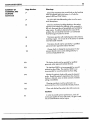
**NO)'E: Some warnings and cautions appear more fhan once throughout the manuai.
They appear in this summary to help direct the user to the proper page and section ofthis
manual.**
S U M M A R Y OF
WARNINGS A N D
CAUTIONS
Page Number
Warnings
4
If the maximum pressure limit is reached, the pre-set tidal
volume may not be delivered to the patient, inspiratory
fime will remain constant, however, and an inspiratory hold
will be maintained with no additional volume being
delivered until the Ventilator cycles to the expiratory phase.
This waming
also appears under Tidal Volume in
the Performance
Characteristics,
Should the blue rubber diaphragm blow outward from
the alarm module's air entroinment ports, remove the
AutoVent immediately from service. And contact your LSP
Distributor.
If the maximum pressure limit is reached, the pre-set tidal
volume may not be delivered to the patient. Inspiratory
time will remain constant, however, and an inspiratory hold
will be maintained with no additional volume being
delivered until the ventilator cycles to the expiratory phase.
This warning also appears under the Pressure
Limit Alarm Module in the
Performance
Characteristics,
19
i4uto7ent2000/3C=C=0
S U M M A R Y OF
WARNINGS A N D
CAUTIONS
(Continued)
Page Nuniber
Warnings
7
Should the inspiratory time control knob on the AutoVent
3 0 0 0 be adjusted after initial setup, it will alter the
patient's BPM and Tidal Volume.
7
The P / N L496 Non-Rebreathing valve is not for use in
toxic atmospheres.
8
Should a mechanical problem devejop or the patient
appears to be experiencing difficulty while connected to
this unit, disconnect the unit immediately and ventilate by
other means. If unable to determine the cause of the
problem, the unit should be returned to an authorized
AutoVent Support Center for service.
8
This device operates with medical gases under pressure,
including oxygen. Do not use oil on this device or operate
near flammable materials.
8
11
This device should only be operated by a qualified
personnel under approved medical direction.
Always check or change the source gases if a low
pressure blender alarm sounds distinguished by a
continuous high-pitched hum.
12
This device should only be operated by qualified
personnel under approved medical direction.
12
The AutoVent 3 0 0 0 is not recommended for use with
patients less than 20kg. The AutoVent 2 0 0 0 is not
recommended for use with patients less than 40kg.
14
Monitor the patients c/ose/y while using the demand
mode. Should the patient's respirations slow, become
shallow or labored, return to initial automatic ventilator
settings immediately.
14
Cleaning procedures must be performed in an
environment free of oil and petroleum-based products.
15
Clean and disinfect'the patient valve after every use.
Cautions
8
In order to provide optimol performance, check all
source gas supplies to assure only clean, dry gas is used,
free of contaminations and/or liquids.
20
S U M M A R Y OF
WARNINGS AND
CAUTIONS
(Continued)
APPENDIX A :
Page N u m b e r
Cautions
10
Read all instructions f/ioroug/i/y before opening the
cylinder valve. Connect all oxygen/source gos pressure
lines to the LSP AutoVent 2 0 0 0 / 3 . 0 0 0 and Patient Valve
Assenibly prior to use. Assure all high pressure outlets are
capped and cylinders turned off or closed when not in use.
10
Always make sure an adequate supply of oxygen or
source gas is available for patient use and transport. It is
advisalDle to hove a back-up regulator availoble to facilitate
change-over in the event a cylinder transfer needs to be
made.
10
Always verify that the cylinder valve is in the closed or off
position (fully clockwise) prior to disconnecting the tubing
assembly or removing the regulator from the oxygen
cylinder.
11
Always follow the blender manufacturer's instructions,
contained in the blender product manual, for exact
connection of the blender to cylinders or wall sources.
Always use a high-flow blender (15 LPM to 150 LPM) for .
ventilatory application.
16
If the flapper valve is twisted or the locating bosses ore
not properly positioned, the Patient Valve Assembly will,not
function properly. Alwoys make sure the valve is flat and
properly seated.
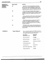
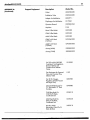
Support Equipment
For your ordering convenience, the following is a list of
adjunct equipment which may be used in conjunction with
or in support of the LSP AutoVent 2 0 0 0 / 3 0 0 0 .
Description
Patient Valve Actuator
Model No.
L004006
Pressure Limit Alarm
L535-fi)||
Pressure Limit Alarm
L535-030
Oxygen Regulator
L270-020 or L270-030
Non-Rebreathing Valve
L496
Corrugated Hose
L535124-010
Patient Valve Supply Tubing
L535114
Oxygen Supply Hose
L535026
\
T<^^^
21
AuioVenilOOO/ZOOO
APPENDIX A :
(Continued)
Support Equipment
Description
Model No.
Outlet
L002768-030
Exhalation Valve
L585045-030
Adapter Anti-lnhalotion
L003571•
Diaphragm Anti-Inhalation
151.7643
Operator Manual
1909005-224
Aspirator
L146
Infant Cuffed Mask
L099-000
Child Cuffed Mask
L099-002
Adult Cuffed Mask
L099-005
Child Tru-Fit Mask
(10/Box)
1.595060-020
Adult Tru-Fit Mask
(10/Box)
L595060-050
A i P A ' a y (Adult)
L002882-050
Aln/zoy (Child)
L0028B2-020
Kit 109 and Kit 002-983
Combined. Test Regulators,
Demand Valves and
Constant Flow Selector
Valves
LOI 0 0 9 0
Test Equipment for Demand
Valve and Constant Flow
Selector Valve
L109
Test Kit for Oxygen
Regulators Outlet Pressure
and High F ow}
L002983
Orange Molded Cose for
" D " and Jumbo " D " Size
Portables
L040088
Child Bag Mask Kit,
Child Tru-Fit Mask,
Cardboard Box
L238-210
Adult Bag Mask Kit,
Adult Tru-Fit Mask,
Cardboard Box
.
Mouth to Mask
Resuscitator, Adult Tru-Fit
Mask (6/Box}
L238-220
L483-010
22
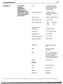
APPENDIX B:
Patient V a l v e
Assembly
Specifications
(All performance
specifications v/ere
obtained by testing at
normal temperature
and pressure.
Flow:
As required in demand
valve mode: 0-36 LPM at
5 0 psig. Depends on
volume setting.
Peak inspiratory Flow:
36 LPM at an airway
pressure drop of Jess than
2.5 cm.H20.
Delivery Pressure:
.60.±5cm.H20 (44 mm.Hg.)
(Insp.) Crack Pressure:
0- to -2 cm.HjO
Exhalation Resistance:
LPM
0-10
11-70
cm.H20 (max)
1.5
3.8
G a s Consumption
Driving G a s :
0.4 LPM Maximum
Dead Space
8 ml. (excluding mask)
Supply Pressure:
4 0 to 6 0 psig.
Operating Temperature:
OTto 125T
Storage Temperature:
-40°F to 160°F
Inlet Fitting:
Standard male oxygen
DISS.
Filter:
2 5 Micron Stainless
Steel Mesh.
Outlet:
22 mm. outside diameter
X 15 mm. inside diameter
(fits standard medical
masks, endotracheal tubes
and tracheostomy tubes).
Weight:
16o2./450g.
Material
Body:
Anodized aluminum
Cover:
Polycarbonate
Outlet;
Polysulfone
Inlet Fitting:
Plated brass
23
AutoVenXZOOO/ZOOO
APPENDIX C:
Control Module
Specifications
(All performance
specifications w e r e
obtained b y testing at
standard temperature
a n d pressure
Supply Pressure Range:
4 0 to 6 0 psig
Storage Temperature:
-40°F to 1 6 0 T
Operating Temperature:
0°F 10 1 2 5 ^
Frequency: (AV 2000)
8 to 15 BPM
Frequency: (AV 3000 Only)
8 to 20 BPM
Tidal Volume:
4 0 0 to 1200 ml.
Tidal Volume: (AV 3000 Only)
2 0 0 to li200 ml.
Flow Rate;
12 to 3 6 LPM
Inspiratory Time;
Approx. 2 seconds
Inspiratory Time: [AV 3000 Only) Approx. 1 second {(Md Selling)
Approx. 2 seconds [Adult Setting)
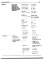
APPENDIX D:
LSP O x y g e n
Pressure Regulator
Specifications
(Model No.'s L270-020,
L270-030,L280-020and
L280-030)
Expiratory Time;
2 to 5.0 seconds
l:E Ratio:
1:1 to 1:4
Dead Space in Patient
Valve Assembly:
8 ml.
Weight:
24 o z . / 6 8 0 g .
Expiratory Resistance;
5 cm.H20
Minute Volume:
1.8 to 2 4 A P M
Case Material:
Polyester
Input Connection:
Plated brass
Output Connectors:
Plated brass
G a s Consumption
Driving G a s :
0.4 LPM Maximum
Supply Pressure:
5 0 0 to 2 2 0 0 psig
Proof Pressure:
8 0 0 0 psig
Outlet Pressure:
High Flow Outlets;
5 0 ± 10 psig at 2 2 0 0 psig
Flow Capacity:
High Flow Outlets:
100 LPM minimum
Constant Flow Outlet:
1,2,4,6,10,15,25, LPM
or 0.5,1,2,3,4,8,15,LPM
Outlet Fitting;
Stondord Male Oxygen DiSS.
Constant Flow Outtet;
1 / 4 " barb
Operating Temperature:
-30"Fto 124°F
Storage Temperature;
-40°F to 160°F
Outlet Pressure Relief
Point:
100 psig Maximum
Filter;
25 Micron Stainless
Steel Mesh
24
i4utorent20OO/300O
APPENDIX D:
(Continued)
Material
LSP O x y g e n Pressure
Regulator
Specifications
Body:
Anodized Aluminum
Knob:
Polycarbonate
I
Outlets:
Plated Brass
Supply Pressure:
5 0 0 to 2 2 0 0 psig
Proof Pressure:
8 0 0 0 psig
Outlet Pressure:
High Flow Outlets:
4 0 to 6 0 psig
Flow Capacity:
High Flow Outlets:
100 LPM
Outlet Fitting:
Standard Male Oxygen
DISS
Operafing Temperature:
-30°F to 125°F
Storage Temperature:
-40''F fo 160°F
Outlet Pressure Relief
Point:
100 psig maximum
Filter:
25 Micron Stainless
Steel Mesh
Body:
Anodized Aluminum
Outlets:
Plated Brass
M o d e l No.'s L735-060
a n d L l 06-060
APPENDIX E:
The conversion chart values are calculations which approximate actual performance at
various altitudes, but do not represent guaranteed performance specifications.
AutoVent 2 0 0 0 / 3 0 0 0
Altitude Conversion Chart
Tidal Volume Settings (ml.)
Life
Support
Products
Altitude
200
300
400
500
600
700
800
900
1000
1200
226
339
452
565
678
79]
904
1017
1130
1356
(ft.)
1000
2000
3280
I
6560
I
254
| 381
I 508
j
635
|
762
|
889
I 1016 I 1143 I 1270
1524
3000
9840
288
432
576
720
864
1008
1152
1296
1440
1728
4000
13120
328
492
656
820
984
1146
1312
1476
1640
1958
5000
16400
374
561
748
935
1122
1309
1496
1683
1870
2244
6000
19680
460
690
920
1 150
1380
1610
1840
2070
2300
2760
25
i4utoVent20C=0/3000
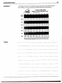
APPENDIX F:
The values in this chart are calculations which approximate actual performance at
various settings, but do not represent guaranteed performance specifications.
AutoVent 2000/3000
Oxygen Cylinder Depielion Times*
Breaths per minute
12
14
16
18
20
Cyi.
52
49
32
45
42
28
40
37
24
36
33
22
32
30
20
E
Jmb. D
D
83
78
50
72
68
44
64
60
39
58
54
35
52
49
32
E
Jmb. D
D
92
86
56
83
78
50
76
71
E
Jmb.D
46
D
162
152
148
138
99
90
E
136 y
127' Jmb. D
D
82
Tidol
Volumo
1200
66
64
41
1000
62
58
38
800
600
500
400
162
152
99
148
138
90
136
127
117
110
103
96
83
71
63
262
245
159
243
227
227
212
138
200
187
179
300
200
NOTES:
148
122
168
109
26
NOTES:
Limited O n e (1) Y e a r W a r r a n t y
LSP worronls ihis producl to be free from defecls in maleriol ond
workmonsliip for a period of one (1) year from lhe dole of manufaclure.
This Worfonly is expressly condilioned on connplionce wilh oii Inspeclion
and prevenlalive mainlenance requirements os set by oppllcoble
governmenl agencies ond os specified by LSP.
k
K
k
k
k
K
K
K
This Warranty is extended by ISP only to the first purchaser of the
product from either ISP or from an authorized distributor.
LSP'S OBLIGATIONS A N D PURCHASER'S REMEDIES UNDER
THIS W A R R A N T Y ARE LIMITED A S F O L L O W S : In lhe evenl of o
defecl, malfunclion or faiiure to conform to this Warranty, purchaser shall
return Ihis producl lo LSP, with shipping chorges prepaid, wilhin a
reasonable lime after discovery of such defecl, malfunction or foilure to
conform. LSP shall repair or replace (at LSP's opiion) this product if II is
detective, molfunclions or foils to conform lo Ihis Worronljr, ond sholl return
il lo the purchaser wilh shipping charges prepaid ond without ony
odditionoi charges due to costs of repair or replacemenl.
In the evenl lhe producl returned by purchoser is nol defective, hos not
molfunclioned and does conform lo this Worronly, LSP shall nol be
obligoted lo repair or replace the producl and shall nol be obligoled for
shipping chorges for relurn of the producl lo the purchoser.
LSP shall In no event be liable for any consequentiol damages, nor for
loss, domages or expenses direclly or indirectly orising from lhe use of Ihis
product.
Disclaimer of Other Warranties
THiS W A R R A N T Y IS IN PLACE A N D IN UEU OF ALL OTHER
WARRANTIES OR REPRESENTATIONS, EXPRESSED O R IMPLIED,
I N C L U D I N G , B U T N O T LIMITED T O , W A R R A N T I E S O F
MERCHANTABIUTY OR FITNESS FOR A SPECIFIC P U R P O S E , B Y
OPERATION O F L A W OR OTHERWISE.
This Worronty does not opply lo malfunction or domoge resulting (rom
accident, ollerotion, misuse, abuse of the producl, improper prevenlotive
mainlenance, storage ot exireme lemperatures or exireme environmenis
beyond design limils, or, where oppropriote, improper use of lhe product
by unlroinea persons. This Warranty does nol opply lo any plastic or
rubber components since Ihey con be affecled ooversely by undue
exposures to heot, sun, water, ozone, or lo olher deleriorolive elemenls.
LSP has nol authorized ony olher firm or person lo make any
representations concerning ihis producl nor to assume on LSP's behalf ony
liability in ony Way connecled wilh lhe sole or use of Ihis producl.
This Warranty becomes void immedialely. should ony repoirs of, or
olferotions lo ihis warranted producl be made wilhoul oulhorizotion by ISP.
Producfs
1720 Sublelte Avenue • Sl. Louis, M O 63110
TEL: 314/771-2400 • FAX: 314/771-0650
\mi'
^
'<'!ll