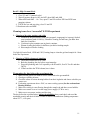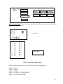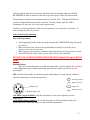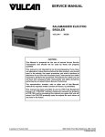
1
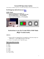
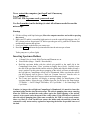
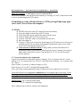
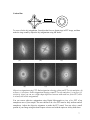
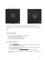
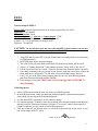
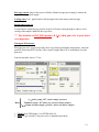
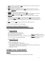
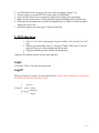
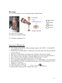
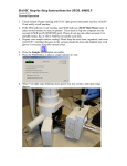
Tecnai F20 Operation Instruction Specifications Imaging Modes: TEM/STEM Accel. Voltage: 200KV Cs: 1.2mm PTP Resolution: 0.24nm Information Limit: 0.14nm Source: Field Emission Tilt Range: ± 30° (normal holder) Tilt Range: ± 70° (special holder) Ancillary Equipment CCD Camera Video Camera GatanTM Imaging Filter Environmental Cell Single-Tilt Heating Stage Double-Tilt Heating Stage (800° C) Techniques Energy Filtered Imaging Environmental Cell Microscopy EELS HRTEM Z-contrast Imaging The FEI Tecnai F20 is equipped with a differentially pumped environmental cell for in situ studies of gas-solid reaction kinetics and mechanisms. This system can handle gas pressures up to 10 torr (1 torr = 133.322368 Pascal), has both heating (800°C) and cooling (liquid nitrogen: (-173 Centigrade) holders for controlled-temperature studies and is equipped with a post-column Gatan Imaging FilterTM (GIF) for electron energy-loss spectroscopy and energyfiltered diffraction and imaging. ⎧ 1 − − − TEM ⎫ Mode in the back of TEM ⎨ ⎬ ⎩ 2 − − − ETEM ⎭ ⎧4 − −turbo pump : 10 −6 ⎪ Meter ⎨5 − −turbo pump : 10 −6 ⎪ 2 − −column vacuum ⎩ Tel: Karl wise: 5-3831; Dr Sharma: 5-4541; Dr Crozier: 5-2934 1 Tecnai F20 Operation Guides On-line help is available by press F1 or click the toolbar Help in Tecnai user Interface (TUI). For Emegency Instructions see here Initial check Following buttons indicate the microscope is on: • System On/Off Buttons --- Off button is lit (red); • Vacuum Enable Button --- Vac is lit (white); • High tension Enable Button --- HT is lit (white) Instructions to use the Tecnai F20 in TEM Mode (High Vacuum mode) CHECK: 1. Check on the box hanging below the control boxes that microscope is in TEM mode i.e. a green light glowing by TEM sign. 2. Valve # 4 is closed; valve # 5 and 8 are open. High Vacuum Mode Valve Status V0 - open V2 - open V3 - closed V4 - closed V5 - closed V6 - closed V8 - closed V9 - open or closed V10 - open or closed 2 Never restart the computer; just logoff asu1 if necessary Log in, if needed: TECNAI F20: log name: asu1; password: asu1 Use the Launcher (on the desktop) to start all software needed to run the microscope. Startup 1. Fill the cold trap with liquid nitrogen (Move the computer monitor and avoid to spraying the screen) 2. Make sure HT enable is on and the high tension is on at the required high tension value. If HT is down (such as forget input UIC before open the gun valve); push the HT button first and then high-tension and operate. 3. Load your sample in the holder you want to use. 4. Reset the holder and insert the specimen holder into the microscope column. Turbo pump on ⇔ yellow (light) Inserting Specimen Holders • • • Column Valve is closed, High Tension and Filament are on. Reset Holder (Stage - Control - Reset holder). Hold the specimen holder with the airlock pin parallel to the small slit in the CompuStage front plate (‘Close’ position at roughly four o'clock). Carefully insert the end of the specimen holder into the airlock cylinder and slide the holder in until a stop is reached. At this point the pre-pumping of the airlock will start as indicated by the red light on CompuStage which will be illuminated. Make sure that the airlock pin falls properly into its groove. Check on “Vacuum Overview” that the valve to column is closed and valve between airlock and turbo pump is open. • The Tecnai user interface will display a message asking for identification of the specimen holder. Select the type of holder from the list and press the Enter button. ‘ST Holder’ --- for FEI Single Tilt Holder; ‘ST Cryo Holder’ --- for Gatan Single Tilt Cryo Holder. Caution: As long as the red light on CompuStage is illuminated, it is unsafe to insert the specimen holder further into the microscope. The airlock pumping time starts counting when the TMP has reached the ready status again (the initial opening of the airlock causes it to lose speed and so drop out of the ready status). If the LED doesn't switch off after the airlock pumping time (plus some seconds for the TMP to reach ready status), there very likely is a leak. In that case remove the holder and wait until the system has returned to ready status and try again after inspecting the holder for possible sources of the leak. 3 • When the red CompuStage light has been switched off, rotate the specimen about 120 degrees counter-clockwise as far as it will, then allow it to slide in further into the microscope. Caution: Maintain a firm grip on the holder while it is sliding in (it is being sucked in by the column vacuum) to safeguard against any possible damage to CompuStage or holder. Once the holder is fully in, carefully tap a few times with a finger against the cap of the holder to help it settle into position and thereby improve stability. 5. 6. 7. 8. Turn off the turbo pump manually by clicking the sign “Turbo Pump”. Switch the filament on to the required setting (Do not change the setting!). Check the vacuum (Tecnai G2→Vacuum Overview) If IGP 1 < 15, input your UIC and open column valve (yellow= close; gray=open). The beam should be now visible. If you have not logged off the previous user then make sure microscope is not in EFTEM mode. Do the alignment in TEM mode, not in the EFTEM mode. Deselect EFTEM mode by clicking on “EFTEM” sign. Tune→Direct Alignment: May be the reason of condenser astigmatism Gun tilt Gun shift Beam tilt PP X Beam tilt PP Y Beam shift Rotation center (250 kx) Coma-free Alignment x Coma-free Alignment y Coma-free pivot point x Coma-free pivot point y Off-axis shift (TV) L1: Reset Defocus; L2: ScreenDim; L3: Spotsize -; R1: Screen lift; R2: Toggle µp/np; R3: Spotsize +; MFX: image shift X; MFY image shift Y (Search→MF knob) Direct Alignments Find the beam. Center the beam by the Beam Trackball (跟踪球) (LP). 9. Eucentric focus: Specimen height (Z height) • Set Mag to 10k x, spot 3 or 4, shift specimen into the field of view. • Press Eucentrical Focus button (RP) 4 Stage ⎯ Control ⎯ Alpha Wobbler (±15o), minimize the side way motion of the image with Z Axis Height control (RP). • Click on Alpha Wobbler again to quit. 10. Rotation Center • Set Mag to 30k x, shift an image mark to the center of screen. • Go to workset Tune Æ Click on Condenser, click on one of the three channels. Center the beam by Beam Trackball (LP) and spread the beam by Intensity (LP). • Minimise the image shift by adjusting Multifunction X/Y knobs (LP and RP) • Click on Done in Workset to quit the rotation centre correction. 11. Focus Low mag: Find a recognizable feature from your sample. Start specimen wobbler (search→wobbler; reset stage). Change the Z-height to stop the lateral movement of the feature. High mag (125k): focus the condenser; change the Z-height in positive or negative direction until diffraction ring disappears; or change Z-height (tab; not push continuously) to obtain minimum contrast. 12. Spot size 1 (C1: its function is to create a de-magnified image of the gun crossover and control the minimum spot size obtainable in the rest of the condenser system; the largest and brightest spot size is 1). For HREM images spot size 3 is a good compromise. 13. Center the condenser aperture (CW and CCW) 14. C2 astigmatism (Tune→condenser→multifunction; medium C2 intensity) →turn off (condenser astigmatism and gun shift affect each other) 15. Follow the Direct alignment Gun tilt (Only for experienced users. Not always needed): at low mag make the bright spot at the center of the crossover using MF knobs. • Gun shift: Focus the beam and check the position of the bright spot in the halo. Bring it to the center using multifunction (MF) knobs as shown below. Beam tilt X and Y: Make two points to one point suing MF knobs. Beam shift: If the beam disappears from the screen, then go to low mag till you see it on the screen. Use MF to move the beam to the screen center. Rotation center: Defocus the beam, identify a feature on your sample and stop its lateral movement using MF knobs. (250kx, high mag) (It is easier to do it in the TV; but you must be in EFTEM mode to use TV) Focus (outer-big knob) Focus step (innter-small knob) TV camera: EFTEM Camera for software: Camera 5 High magnification --- spread the beam; low magnification --- beam shrink Check TV connection: 1. cable input; 2. power by Panasonic DVD Defocus the condenser and adjust the beam intensity by focusing (C2) on TV monitor not on the screen to avoid damaging the CCD camera If something is wrong with the software or TEM, just logoff and login again (asu1; asu1). Never restart the computer. 16. EFTEM EFTEM (lift up the screen)-TV image-Decrease the intensity Focus the sample (carbon film) in the TV image Find a large hole in your sample and center it on the screen. Click on ‘Align ZLP’ (Zero loss) (in the hole) Click on ‘Tune GIF’ (takes several minutes) (in the hole) Move the sample in Click on CCD preview (Camera) to obtain image on CCD camera: focus.You can use multifunction for fine movement of the sample (spread beam on the screen, lift the screen, focus the beam and sample on TV). Gain reference in DM (If needed): In image mode, perform ZLP and tune Gif alignments (middle is green and use small keyboard “enter”). Prepare gain reference: Image mode; 5mm hole in screen; Center the hole in TV; TV out; lift screen and answer questions. 17. Correct the objective lens astigmatism Camera→Set camera for continuous exposure, binning 4, 0.25 sec exposure time for “search’; binning 2 , 0.5 sec exposure time for “ Preview” and single frame, binning 1, 1 sec exposure time for “Aquire”. Select ‘search’ or ‘preview’ to obtain an image on CCD. Select ‘Process→Live→FFT’ in Digital Micrograph (DM). Tune→Obj. Stig→using multifunction make it round (use focus to adjust the size of circle) Correct the objective lens astigmatism: underfocus obj. lens (bright edge) to get rings. Correct the astigmatism by using MF knobs and make the rings round. Continue the process after changing focus, one step at a time until a single perfectly round ring is observed at Sherzer focus. Objective lens: CW→overfocus (black edge) CCW→underfocus (bright edge) FEG: condenser lens overfocus; objective lens underfocus 6 Carbon film Defocus To correct for the obj astigmatism, first adjust the focus to obtain rings in FFT image, and then make the rings round by adjust the obj astigmatism using MF knobs. (a) (b) (d) (c) (e) (f) Objective astigmatism using FFT: Bad astigmatism showing a distorted FFT at (a) underfous, (b) at focus, (c) overfocus. Good Astigmatism showing round FFT at (d) underfocus, (e) at focus, (f) overfocus. (since you can see a slight shape difference between under and over focus FFT, there is actually still a little astigmatism). You can correct objective astigmatism using Digital Micrograph to view a live FFT of an amorphous area of your sample. The area chosen to do a live FFT must be fairly uniform and all amorphous. Adjust the objective stigmators to make the FFT round. You can select a small portion of your image using the dotted square selector tool with the option or alt key held down. 7 Diffraction astigmatism correction. Astigmatic No astigmatism For best results, correct for objective astigmatism right before recording images as near the sample area of interest as possible. Fine tuning will be required from time to time throughout the session. Enjoy! Shutdown Procedures Click on ‘EFTEM’ to bring microscope in TEM mode. Go to ‘Search→Stage→Reset Holder. Click on “Col. Valve Close” to close V4 and 7. Unload the sample and sign in the logbook Removing Specimen Holder • • • • Close the column valves. Make sure the specimen holder is in a safe position (set all axes to 0 by Reset Holder). The red CompuStage light should be off. Pull the holder as far out of the CompuStage as it will go, then rotate it clockwise as far as it will go (about 120 degrees). Use one thumb hold the blue cover plate and the silver ring on the CompuStage. Carefully extract the holder from the airlock (you have to pull against the vacuum remaining in the airlock). 8 EELS General Setup for PEELS Energy shift: depends upon the element to be analyzed, generally over 100eV Dispersion: 1.0ev/channel Entrance aperture: 2 mm Condenser aperture: 3; spot size: 6; camera length: 1.75M Number 5 in the small keyboard = whole EELS spectrum Acquire + alt = set up parameter for acquire mode Exposure: 1 second; bin CAUTION: Do not lift the screen and start collecting EELS spectra unless you are sure that beam intensity is very low. You can easily burn the CCD!!! 1. Align ZLP and also tune GIF if you not already done so in image mode (see instructions for TEM operation). 2. In EFTEM mode select spectrum imaging. 3. TIA control will ask you to defocus the beam. Keep the screen down and hit return. 4. Select 1 eV/channel dispersion, 2 mm entrance aperture, energy shift of 200-300 eV. 5. Lift the screen and click on ‘search’. Focus the spectra using elemental peaks if possible. 6. If no sharp elemental peaks are present in your spectra, bring the screen down, reduce the beam intensity by defocusing C2 to fill entire screen and change energy shift to 0. 7. Use Fx, Fy, etc in the filter control window make the zero loss peak intensity highest, peak form Gaussian and with smallest FWHM. 8. Focus using zero-loss peak. Make sure to reset energy shift to 100-300 eV after focusing. Collecting spectra 1. Select a different area from the area you want to get EELS spectrum 2. In the diffraction mode, center it to make the intensity highest (0.6mm entrance aperture, search mode) by moving the diff shift multifunction 3. Use the whole EELS spectrum to see the intensity change 4. Use entrance aperture: 0.6mm to center the spectrum in the entrance aperture (maximize the intensity) and use 2mm (more intensity) to acquire. You can use 3mm for more signal (if 0.6mm is centered, you don’t need to center other apertures). 5. Find area of interest; put the area at the 9 or 10 clock on the small ring on the screen, so you can see the image in the TV easily × Beam; 10 clocks Screen 9 Select ‘Object’ window in DM →image display→stop Auto high In image mode: Use beam shift to obtain the highest intensity of EELS spectrum. In diffraction mode: diff shift to obtain the highest intensity of EELS spectrum. Theoretically, the diff pattern is from the same area 1. Diffraction mode, defocus the shadow image Beam size Shadow image Select the eV range of interest by changing the energy shift value and collect the spectra! Good luck! E-TEM mode operation: Outlet Inlet Outlet Needle valve to close (clockwise) V4 Obj aperture Status and functioning of various valves: Gas Purging 1. Open V5 to let gas in. 2. Close V5 and open V4 and V10 (may have to ramp down the turbo pump). 3. Close V4 and V0 and open V3. In Situ Mode 1. Open V8. 2. Close V2 and open V6. 3. Open V5 to let in gas. 10 Back To High Vacuum Mode 1. Close V5 and V3 (manual valve). 2. Wait till pressure drops in AP1 and AP3, then AM2 and AM4 3. When AM2 and AM4 ~ 10-5 Torr, open V2 and V0 to allow IGP4 and IGP0 start pumping column. 4. If IGPs are low and not rising, close V6 and V8 5. Shut down turbo and MDP Cleaning issues for a “successful” E-TEM experiment 1. Cleaning of hex ring, washers and grids a. Put them in the glass beaker filled with (propanol, isopropanol or isopropyl alcohol, semi-conductor grade 99.999%); Ultrasonic cleaning for half hour; put under heat lamb for 60 minutes. b. Put them in glass container not in plastic container. c. Plasma cleaning the holder for half hour just before loading sample. d. Heat sample rod before loading Use light (Sylvania flood, 150W and 120V) heating lamp to clean the grid and sample for 1 hour before the experiment. 2. Cleaning of TEM column and plumbing a. Check the recent users for E-TEM. b. Bake the plumbing the day before experiment day. c. Purge the plumbing and e-cell separately with H2 and N2; first 50 Torr H2 and then 200 N2. d. If Karl can bake the TEM column, have it done. Preparation the day before the experiment day 1. Make sure the gasses you want to use are connected to the gas manifold. 2. Check gas cylinder pressure. 3. Check the status of various heating holders from their logbooks and choose a holder you want to use. 4. For heating experiments above 500C, set water-cooling system (See the section about Heating holders). 5. Make sure cooling is water flowing through the sample rod and there are no bubbles. 6. Make sure current is set to 0 on hot stage power supply (CCW to zero). 7. Make sure to use proper washers and hex ring. The day before the experiment day: baking the plumbing always and check who used the machined recently and check if there is water or carbon contamination. (Baking temperature about 1250C, v8 is open) 11 Read only Stage Cryochambe Column 1250C 1250C × Bake all Bake RC off Baking the plumbing: V5 and V8 is open, needle valve and N2 valve open (not main valve) for baking the N2 plumbing line 3 4 5 2 1 Control Box ×4 ×5 ×8 ×1 ×1 #1 #2 #1 #4 # #5 # #7 mode# #8 mode# #1 Control panel Valve Control Box Operation The five position rotary switch is used to select the desired operating mode: Mode 1 = TEM; Mode 2 = ETEM; Mode 3 = VENT; Mode 4 = PUMP OUT AFTER PURGE; Mode 5 = START/SHUTDOWN 12 Once the desired mode has been selected, the black button in the upper right corner MUST BE PRESSED in order to make the control box open/close proper valves for the new mode. The push button switches are for manual control of a specific valve. If the green LED below a switch is illuminated manual control is allowed. Pressing a button while the LED is illuminated will cause the valve to go to the opposite state. The three red warning indicators flash when an emergency, or over-pressure is detected. As of this writing they are not yet active. After the baking the plumbing Day of the Experiment 1. Select appropriate holder, load you sample and align the TEM/EFTEM using instructions given above. 2. Make sure all the inlet valves to the gas manifold are closed. For all of the valves, clockwise turn is to close the valve 3. Make sure any water/precursor containers attached to the microscope gas inlet are closed. 4. Select ETEM mode on the control system. Open Valve#5 and 8 manually. DONOT USE ANTICONTAMINATION DEVICE (Liquid N2 trap) in ETEM Mode. Heating Holders: There are four heating holders available and each holder is clearly marked. Pay attention to the loading instructions, washer and hexring material for the holder you choose for your experiments. IDT is double tilt hot holder, check thermocouple and heating wire connection for oxidation; check the connection (envision and inspection) Hexaring (inconel) Washer (inconel) Heater (0.7) Sample (Pt) Washer (inconel) Thermocouple (34) G03 holder (single tilt holder): after the experiment, record in two logbooks (current— temperature) Load sample (single tilt holder): special tool (big ring) to avoid twisting the metal wires (reduce the stress); sandwich sample to avoid melt and contamination 13 Hot stage control: plug for the power of holder (Gatan hot stage power supply); connect the stage to hot stage power supply. Cooling water: use 1 gallon bottle to fill the upper barrel and connect with hot stage Put the stage cover on It is advisable to obtain the gas pressure in the E-cell before staring heating in order to avoid cooling of the sample (and drift) due to gas flow. *** Pay attention to FEG IGP current (<0.5µA) when gun valve is open, this is very important Check gun IGP current: When the gun valve is open (especially, there is gas flowing and higher temperature), check the gun IGP current and IGP2 vacuum, if the current is higher than 0.5µA, immediately close the gun valve. Gun runs normally above 10-9 torr. ⎧ 4 − − turbo pump : 10 −6 (outlet sample pressure ) ⎪ Meter ⎨ 5 − − turbo pump : 10 − 6 ( inlet gas pressure before sample ) ⎪ 2 − − column vacuum ( sample pressure : above and below sample ) ⎩ 1. Change from TEM mode (1) to E-TEM mode (2). 2. Push V5 (gas in) and V8 (by-pass valve) to manually open them. 14 3. Close all inlets to the gas manifold, open inlet from the gas to be used and let it pump out any residual gasses form the line. 4. Close the gas inlet to the manifold. 5. Open gas main valve (regulator) on the tank, open second valve (black valve) to the manifold. Fill it up to approximately 300 torr pressure and close the inlet valve and main valve (regulator) 6. Connect the cooling water to heating holder (if required) 7. Connect the holder to the hot stage power supply; turn the current knob to zero (counter clockwise); push power and heater; test it (check the wire is not broken). 8. Make sure gas inlet valve to the microscope column (needle valve and V3) are closed (clockwise) 9. To let the gas in the column, open V3 first and then slowly open the needle valve; gauge 5 and 4 will rise; adjust needle valve slowly to make gauge 5 to desired pressure; Make sure that the reading of gauge 4 and 2 is not higher than 10-3 torr (Gauge 2 should be better be 10-4 torr). 10. Input your UIC and open the gun (check FEG IGP not higher than 0.5µA) V5 and V8 is the most important valve during purging Flowing the gas, Temperature will drop Pay attention!!!!!!! Increase temperature, repeat gas filling + adjust temperature until balance a. purge plumbing First with H2 and then with N2 (easier one). Close V3 (black valve) and metal needle valve Fill mixture gas tank less than 660 torr Slowly open metal needle valve and observe the Meter 4 and 5 V3 close, V5 and V8 open for purging plumbing Meter 4: plumbing line front part (7.5×10⁻³ limit, if higher, it can’t tell) Meter 5: plumbing line back part (1.07×10² limit for N2) b. purge TEM e-cell V3 and V5 open and V8 close 1. Close V3 (E-TEM mode, V5 and V8 open) 2. Fill the gas manifold with N2 and/or H2 up to 660 Torr. 3. Close needle valve and V8; open V3 and slowly open the needle valve until all the gas from manifold is pumped out, close needle valve 4. Repeat steps 1-3 twice. Setup is over. Good luck!!! Some tips: 1. H2 is the most difficult gas to vacuum, so normally use H2+N2 mixture. 15 2. 3. 4. 5. 6. In ETEM mode, before open gun valve, the check the reading of gauge 5 is 8. Always keep an eye on the FEG IGP current when in ETEM mode. Keep carefull records of time, temperature and pressure during entire experiment. Make sure the cooling water is flowing through using the heating holder rod all the time. When increase the temperature, decrease the magnification to 52000x to avoid loosing the sample area due to drift. 7. Record the tank pressure and gauge 5 readout all the time E-TEM Shut down 1. Close V5, (V8 close is ok) pump all of gas out of the e-cell (#4 and #2 at 5*10-6 torr) 2. Remove specimen holder Close V3, change E-TEM to TEM, open V5 and V8, pump all of gas out of the plumbing and mixing tank. 3. Purge the plumbing and the column with nitrogen gas. 4. *Sign the two logbook (general and hot stage logbooks) Login You need a Tecnai 12 account and a password. Logoff When you finish your session, you must logoff the PC. Do not select ‘Shut down’, because that will effectively shut down the microscope! ⎧ ⎪ preview ⎪ Camera ⎨ search − turbo ⎧continious ⎪ ⎪acquire⎨ sin gle ⎩ ⎩ 16 Hot stage: Two wires for heating; two wires for thermocouple; alumina furnace hexaring washer sample washer Two inner wires for heating Two outer wires for thermocouple ****Condenser astigmatism**** Some tips for TEM operation: 1. If the column vacuum is down when you change sample, wait for IGP1 < 15, then add HT and operate FEG current 2. Plasma cleaning: put the holder in; vacuum; power on (clean) and set the time; turn off and take the holder out 3. If you turn on high tension: need waiting about 5 minutes, then click on ‘operate’ 4. FEG register: set the saved setup to load good alignment (it works only logoff and save it) 5. Focus: eucentric focus; Z-height to vanish the diffraction ring; TV to focus 6. Before correcting for obj astigmatism, defocus to see the rings 7. For correcting obj astigmatism, set integrate time: 0.25 s with binning = 4 (or search mode). 8. Before lift the screen, make sure that the beam intensity is very weak (direction?) to avoid burning the CCD camera 9. Underfocus: counter clockwise × Beam; 10 clocks 10. Center of entrance to TV image: Screen 11. Quickly take the image (preview: change some setup) 17