1
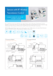
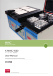
/ & 8 Portable Multi-logger ;339 p o t s e n O e Th r e g g o L a t a D 2 5IF)JHI4QFFE-PHHFS7PMUBHF Wonder. Powerful Functions and Performance. table r o P It's re. o m d an First in its class High-speed, Simultaneous Sampling on All Channels High-speed, simultaneous sampling without any time lag on all 8 channels and speeds up to 10μs Super-wide Voltage Input Range The wide input range from ±20 mV to ±500 V. It enables high-voltage measurement capability meeting versatile needs. Voltage input is selectable from the BNC terminal or the M3 screw terminal. Secure Isolated Multi-Input Each channel is equipped with its own isolated circuit. Thus, multifunction input for voltage, temperature, humidity, logic and pulse is secured. Advanced PC Connectivity USB port, LAN port and USB flash drive available The most appropriate connection can be selected depending on the situation. Input signal Voltage Temperature Humidity Logic Pulse List of features Maximum 8 channels simultaneously All channels isolated Voltage Thermocouples ±20mV to ±500V K,J,E,T,R,S,B,N,W LAN USB 64MB function flash drive internal memory 5.7inch TFT LCD Easy-tonavigate menus 2 hour battery Display switch 16 bit resolution Portable Multi-logger *Full-scale photo W232×H150×D80(mm) ZR-RX70A-E 2 e l b a t r o P A 0 7 X R R Z The . r e g g o L i t l u M t a g n i n n u Now r . e c i o h C r u yo For Laboratories 3 For Oscillation Tests For Environmental Tests 4 Start Powerful Engines. Meeting Versatile Testing Requirements Optimum Setting for Each Intended Use Multifunction Input Appropriate Sampling Speed for Any Application Voltage … ±20mV to ±500V Temperature … Thermocouples: K, J, E, T, R, S, B, N, W Humidity … Humidity Sensor (optional ZR-XRH1 required) Logic Pulse (Rpm/Count /Inst.) M3 screw terminals for thermocouple connection … 4 channels in addition to the analogue 8 channels High-speed sampling at speeds up to 10μs is possible. Thus it is suitable for applications such as drop tests and oscillation tests that require high-speed sampling. Data of lengthy applications, such as endurance tests and environmental tests, can be continuously logged to the flash memory at a sampling interval of 1ms or over. Applications at High Speeds Applications at Low Speeds r&OEVSBODFUFTUT r5FOTJMF Compression tests r&OWJSPONFOUBMUFTUT r%SPQUFTUT r*NQBDUUFTUT r0TDJMMBUJPOUFTUT Pulse selectable from "Rpm", "Count" or "Inst." mode for each channel Potential recording time (for 8 analog channels) Recording medium 100μs 500μs 1ms 10ms 100ms 1s Approx Approx Approx Approx Approx Approx 1min 40 sec 8min 20 sec 16 min 40 sec 2 hours 40 sec 1 day 3 hours 11 days 13 hours Internal RAM 10 sec Internal flash memory - - - Approx 1 hour Approx 11 hours Approx 4 days Approx 46 days USB flash drive* - - - Approx 2 hours Approx 22 hours Approx 9 days Approx 93 days (Example: 512MB) BNC terminals for voltage input 10μs *Please use a USB flash drive without security function Meeting Versatile Testing Requirements Measurement of High Precision Super-wide Voltage Input Range Simultaneous Sampling on All Channels The wide input range from ±20 mV to ±500 V. It allows the measurement of 100 to 240 VAC power supply waveforms. The simultaneous measurement of power supply voltages, currents and sequence controls are possible by use of logic input and a clamp meter. A high-speed AD converter is equipped on each input channel. As the high-performance ICs can simultaneously control all channels, high-speed simultaneous sampling is possible. Simultaneous sampling Sequence: Logic Current : Clamp meter A/D Multiplexer sampling Input terminals Input terminals A/D A/D A/D Thermocouples Voltage Storage medium Storage medium AC power supply Temperature: Thermocouples 5 Separate A/D for each channel Switching Single A/D for all channels Everyday Use. Advanced Usability No Interruptions During Measurement Ultimate User-Friendliness Pulling Up Any Stored Data During Data Logging The cell-phone-like advanced usability featuring a set of cursor keys allow users to easily view enlarged and reduced images of high-speed waveforms. A 5.7-inch TFT large-screen color LCD enables easy observation of waveforms and measurements even in a dark place. TIME/DIV key for enlarging or reducing the time axis. Easy-to-see big screen 5.7 inch TFTcolor LCD Meeting Versatile Needs X-Y Recorder Function Time axis Enlarge 10ms/DIV to 1min/DIV Easy control with cursor keys The product is equipped with FTP client function. It allows users to pull out any data stored in the logger whenever necessary during data logging. Time axis Reduce The analog X-Y recorder function of the product enables users to view correlations between different pieces of data. The function enables the reproduction of pen up/down movements of an analog X-Y recorder. The product can also be used as a 4-pen recorder. Digital data captured with this function can be used for reports and other post-measurement works. Pen up View the movement of the pen Capturing Necessary Data Only The point moves as if the pen moves. Useful Trigger and Timer Functions Different combinations of the trigger and timer functions O f fer a wide variet y of set tings for dif ferent situations. They enable users to eliminate superfluous data and capture the data truly necessary for each situation. Timer Setting Timer mode Start source setting Setting example 1 Pre-trigger Only when data is stored in internal RAM Repeat capture 0 to 100% On, Off and Repeat Intervals Measurement of abnormal signals while a certain device is at work Timer Setting Timer mode Start source setting Stop source setting Repeat capture Trigger settings Daily Cycle Start setting:09 hrs 00 sec Stop setting:18 hrs 00 sec Level CH1(3V rising) Level CH1(2V falling) On Trigger activation points Data capturing Stop trigger 2V 6:00 12:00 18:00 0:00 6:00 12:00 18:00 0:00 Measurement of certain parameters every 20 minutes Timer Setting Trigger settings Timer mode Start source setting Stop source setting Hourly cycle Start setting: 00 min 00 sec Stop setting: 20 min 00 sec Off Off Start Key On Timer period Data capturing 0:00 6 Reproduce and confirm digital data. Copiable data on the screen can be used for reports. Timer period Start trigger 3V Setting example 2 Confirmation of digital data Finishing data capturing in priorty to timer setting Start Key On 0:00 View the trajectory of the pen and capture data Off, Date/Time, Daily Cycle, Hourly Cycle Off, Level Value, External Input Off, Level Value, External Input, Scheduled Time Stop source setting Trigger settings Pen down 1:00 2:00 3:00 4:00 5:00 6:00 Calibration service(charged option) Calibrations and certification on request If a calibration certificate is requested when purchasing the Portable Multi-logger, the inspection date on the certificate will be the same as the manufacturing date. If an inspection date that is close to the shipping date is required, an extra fee and additional time will be required. Ask your OMRON representative for details. PC Connect. Utilize data in any style you like. ZR-RX70 offers more than six types of PC connections. You can utilize data in any style you like. "I want to transfer this data stored in the logger to a PC." USB flash drive Data transfer using a USB flash drive Plug a USB flash drive into the logger, copy data on the drive. Then, pull out the drive from the logger and plug it into a PC. USB flash drive USB Data transfer using the logger as an external drive USB cable Connect the logger to a PC, have the PC recognize it as an external drive and copy data. "I want to view logging data on my PC in a simple way." Logging Data Viewed On a PC A special PC software program allows you to easily view waveforms and other logging data on your PC. Standard PC software Special PC software "Wave Inspire RX" Start the software and select the file you would like to see. Then, you can view data in multiple windows, and zoom up or down waveforms on your PC. Viewing Logging Data in Excel Format LAN Data transfer through an Ethernet network using FTP client software Ethernet Set an IP address on the logger, connect the logger to a PC through a LAN and have the FTP client software copy the data. Data can be copied even during logging. "I want to remote view or remote control the logger." Web Server Function Pre-installed You can remote control the logger from the web browser installed in your PC by connecting the logger with an IP address to the PC through an Ethernet network. "Remote control across different countries is possible by setting a global IP address on the logger." The special software also allows you to save logging data in CSV format. "I want to save logging data in real time in my PC." USB LAN The special software enables real-time data saving in a PC. "The logger can be connected to a PC via USB or LAN connection." "The use of the special PC software and LAN connection allows you to save data from two or more data loggers into your PC." USB cable You can view and control the display and cursor keys of ZR-RX70 on your PC. The NTP client function of the product also enables an easy synchronization of different devices. "PC software is not required." "You can remote control (or view) the logger from a PDA with a web browser." You can also save and convert logging data directly in Excel format. 7 Accessory More Brains. Special PC software ZR-SX10 Can be used as a USB flash memory (1GB) as well. Wave Inspire RX Ver2.0 Wave Inspire RX, a special PC software program for ZR-RX70, allows you to easily compare data of different measurement tasks and observe the waveform of each input signal. It is very convenient when you have to handle the waveforms of a large quantity of data of multiple measurements, multichannel measurements and other measurement tasks. Featuring a number of functions not available in other logging software programs, it allows you to directly grab and drag waveforms, scales and cursors with a mouse. It far excels other programs in its data processing capability and intuitive operability. Major functions. r2VJDLDBMMVQPGUIFDVSTPSr4QFDJBMTFBSDIGVODUJPO r4DSFFO TBWF GVODUJPO $47 TBWF GVODUJPO r3FQPSU printing function 2VJDL0QFSBUJPO High Performance with No Stress The memory-saving program with low CPU load enables stress-free processing of high-speed data. Intuitive control Easy Comparison and Quick Decision Free adjustment function STEP1 Smart search STEP2 Grouping STEP3 Multiple display r$MJDLPOXBWFGPSNTDBMFPSDVSTPSBOENPWF Temperature Display for each input signal Search all the Voltage channels Insert comment at an arbitrary position on the waveform Compare multiple boards (target) Voltage Drag and drop into the "IC Chip Voltage" group Move scale left or right Search selected channels in one operation! After the search the channels have selected status. Move waveform up or down Grouping is simple by drag and drop into the created groups. Easy to view recording setting screen For each group a waveform screen can be displayed, so observation of comparisons between groups is possible. patent pending rChange the position of the wave form with a single click of an icon Display side by side Display superimposed Direct input Pull-down selection Setting and editing can all be completed from this screen! Viewing Data from Two Data Loggers Simultaneously High-speed display of waveforms Wave Inspire RX can be used with OMRON data logger ZR-RX40 as well. If you connect ZR-RX70 and ZRRX40 via LAN connection, you can view temperature data measured by ZR-RX40 and voltage data measured by ZR-RX70 simultaneously, and save the data from the different loggers as one file. You can handle data from the two loggers without any data combining processes. * When sampling speed is 1ms or faster. X-Y display FFT display It Will Save You Money. Value Pack Available A special value pack (comprising of a standard set of ZR-RX70, the special PC software ZR-SX10 and a buttery pack) is available. It sure will save you movey. For further detail, please see Page 9 and Page 10 hereof. 8 System Configuration Standard set Accessories ZR-RX70A-E Accessories C3C adapt*3C cable(CEE) CUser's Manual CUtility disk* Special PC software ZR-SX10 Battery Pack ZR-XRB1 Humidity Sensor(3m) ZR-XRH1 *Content of utility disk –Standard PC software –manual PDF file *Can be used as a USB flash memory (1GB) as well. DC Cable(2m) ZR-XRD1 7=3m Cable(2m) 7 9 Cable(2m) ZR-XRC1 Specifications Main unit Item ZR-RX70A-E Input method Number of input channels All channels isolated input, Imbalanced input, Simultaneous sampling of all channels BNC terminal: For voltage measurement. M3 screw type terminal: For voltage / temperature (thermocouples) measurement. *1 8 CH Sampling interval 10μs to 1 min Input terminal shape A/D resolution Measurement ranges 16 bit Voltage 20, 50, 100, 200, 500 mV, 1, 2, 5, 10, 20, 50, 100, 200, 500 V, 1-5 V F.S. Temperature (Thermocouples) K, J, E, T, R, S, B, N, W (WRe5-26) Humidity 0 to 100% (Voltage 0 to 1 V scaling conversion) ZR-XRH1(Refer to the option.) External input/output sections between input terminals Switch between logic4CH and pulse4CH *2 20 mV to 1 V: ±30 VDC 2 V to 500 V: ±500 VDC 60 Vp-p between input terminal/GND 60 Vp-p between input terminals 1000 Vp-p (1 minute) between input terminal/GND 1000 Vp-p (1 minute) between +/– input terminals Maximum input voltage Withstand voltage Input impedance 1 MΩ ± 5% Allowable signal source resistance 1 kΩ or less Reference contact compensation accuracy *3 ±1.0°C Pulse input *2 *5 Revolutions mode 5 to 20M RPM/F.S.(1,2,5 step) Counts mode 5 to 20M C/F.S.(1,2,5 step) Inst.mode Channel combinations 5 to 20M C/F.S.(1,2,5 step) Start: Data capture starts when a trigger is generated. Stop: Data capture stops when a trigger is generated. Start: Off, Level(Analog/Logic/Pulse), External *2 Stop: Off, Level(Analog/Logic/Pulse), External *2 r Time Level OR, Level AND, Edge OR, Edge AND Mode ↑ H, ↓ L, Window IN *4, Window Out *4 Trigger types Trigger Functions Timer mode Date and Time, Every Day Cycle, Every Hour Cycle Alarm output *2 4CH,Open collector output (5 V, 10 kΩ pull-up resistance) Output conditions ↑ H, ↓ L, Window IN *4, Window Out *4 Input filter OFF, Line, 5 Hz, 50 Hz, 500 Hz Statistical calculation functions Types of statistical calculation *6: Average, Max, Min, Peak, RMS (Maximum of 2 can be set simultaneously.) PC Interface types Ethernet (10BASE-T/100BASE-TX), USB (USB 2.0 HIGH-SPEED) PC Interface functions Memory device Ethernet Web server function, FTP server function, NTP client function USB USB drive mode Internal RAM:1,000,000points, Internal flash memory: Approx. 256 MB External USB Memory slot(HIGH-SPEED) *7 Display 5.7-inch TFT color LCD Display settings Waveform screen + Digital screen, Waveform screen, Digital screen + Calculation Display, screenX-Y display TIME/DIV 10ms/DIV to 24hour/DIV Operating environment Power consumption 0 to 40°C, 5 to 85 %R.H. (15 to 35°C when the battery is used) AC adapter: AC100 to 240 V/50 to 60 Hz DC input: DC8.5 V to 24 V Battery pack *8 28VA (When the AC adapter is used) Weight Approx 1.1kg (Excluding AC adapter and batteries) Vibration resistance Equivalent to automobile part Type 1 Category A classification External dimensions 232 × 150 × 80 mm Accessories User's Manual, Utility Disk (CD-R), AC adapter/AC cable (CEE), User registration Postcard Power supply *1 *2 *3 *4 *5 *6 *7 *8 9 Trigger settings BNC terminal and M3 screw type terminal of the same channel cannot be used simultaneously. A logic alarm cable ZR-XRL1 (optional) is necessary. 23°C ± 5°C At least 30 minutes after the power supply is turned on Filter Line GND connection The logic input cannot be set. Maximum input frequency: 50 kHz, Maximum number of counts: 15 MC (24-bit counter) Real time and data between cursors specified (during data replay) Max. 2 GB (Depends on the type of USB memory in use) 2 battery packs should be mounted when using battery pack. 5FNQFSBUVSF)VNJEJUZBOENPSF Analog Input Measurement Accuracy Item Humidity Sensor ZR-XRH1 (Accessory) ±0.25% of F.S. Voltage Item Description Allowable temperature range Description –25 to +80°C Allowable humidity range 0 to 100% RH Measurement accuracy Relative humidity measurement accuracy ± 3% RH (5 to 98% RH at 25°C) ± 7.0°C Response time 15 sec (90% response when membrane filter is installed) 100 < TS ≤ 300 ± 5.0°C Sensor output 0 to 1V R: 300 < TS ≤ 1600 ± (0.05% of rdg + 3.0°C) External dimensions ø14 mm × 80 mm (excluding cable) S: 300 < TS ≤ 1760 ± (0.05% of rdg + 3.0°C) Cable length 3m 400 ≤ TS ≤ 600 ± 5.5°C 600 < TS ≤ 1820 ± (0.05% of rdg + 3.0°C) –200 ≤ TS ≤ –100 ± (0.05% of rdg + 3.0°C) –100 < TS ≤ 1370 ± (0.05% of rdg + 2.0°C) –200 ≤ TS ≤ –100 ± (0.05% of rdg + 3.0°C) –100 < TS ≤ 800 ± (0.05% of rdg + 2.0°C) –200 ≤ TS ≤ –100 ± (0.1% of rdg + 2.5°C) –100 < TS ≤ 400 ± (0.1% of rdg + 1.5°C) –200 ≤ TS ≤ –100 ± 3.7°C –100 < TS ≤ 100 ± 2.7°C N 100 < TS ≤ 1100 0 ≤ TS ≤ 1300 ± (0.05% of rdg + 2.0°C) ± (0.1% of rdg + 2.0°C) W 0 ≤ TS ≤ 2315 ± (0.1% of rdg + 2.5°C) Temperature*1 Thermocouple Measurement Temperature Range (°C) 0 ≤ TS ≤ 100 R/S B K E T J *1:Operating environment 23°C ± 5°C Left for at least 30 minutes after the power supply is turned on Filter Line GND connection Thermocouple used is T:0.32 ø, other:0.65ø PC Software Item 4QFDJBM1$TPGUXBSF;349 8BWF*OTQJSF397FS "DDFTTPSZ Standard functions 3FWJFXTBWFEEBUBSFBMUJNFDBQUVSFPG1$EBUBNBJOVOJUTFUVQ $47àMFDPOWFSTJPO Waveform operation %SBH.PWFXBWFGPSNEJSFDUMZ #BUDIDIBOHFPG$)TDBMF *OUVJUJWFPQFSBUJPOCZNPVTFXIFFM $IBOHF$)TDBMFT individually by icons Waveform display %JTQMBZTNVMUJXJOEPXT %JTQMBZTBMMUIF$)NVMUJTDBMFTTJNVMUBOFPVTMZ Scrolling for all directions (up, down, right, left) 95EJTQMBZ9:EJTQMBZ''5EJTQMBZ Split display in the single window 95EJTQMBZ9:EJTQMBZ''5 display Meter display selection Configuration function 4NBSU-JTUWJFXTFUVQGVODUJPO 4NBSU(SPVQJOHGVODUJPO Setup in the tab format Captured data #JOBSZGPSNBU4BNQMJOHJOUFSWBMTUPT $47GPSNBU4BNQMJOHJOUFSWBMNTUPT $47DPOWFSTJPONFUIPECFUXFFODVSTPST"MMEBUB'JMFCVMLDPOWFSTJPO Others Cursor function, Comment input GVODUJPO"DRVJTJUJPOTFUVQ4NBSU TFBSDIGVODUJPO&YDFMEBUBUSBOTGFS GVODUJPO"MBSNNBJMGVODUJPO Compatible interface 64#-"/ Compatible operating system 8JOEPXT7JTUB91 Standard PC software 4NBSU7JFXFS39 4UBOEBSE"DDFTTPSZ Cursor function, Comment JOQVUGVODUJPO&YDFMEBUB USBOTGFSGVODUJPO"MBSN mail function Ordering Information Standard set Accessories (Order separately) Item Model Item Model 1PSUBCMF.VMUJ-PHHFS ;339"& Battery Pack ;393# Humidity Sensor(3m) ;393) DC Cable(2m) ;393% Logic Alarm Cable(2m) ;393- BNC Cable(2m) ;393$ Special PC Software Wave Inspire RX ;349 .PEFMTDPNQMJBOUXJUIUIF$IJOFTF3P)4%JSFDUJWFBSFBMTPBWBJMBCMF 1MFBTFDPOUBDUZPVS0.30/SFQSFTFOUBUJWFGPSGVSUIFSJOGPSNBUJPO The temperature detector also abundantly does the lineup. External Dimensions 6OJUNN ZR-RX70 24.6 ZR-RX70 mounting screw holes 2-M4 Depth 6 122 69 3.5 232 185 23.5 75 5 Related Products Max. 200-channel Temperature Measurement Palm-top Mobile Model Standard 10 20 insulated Channels Channels *OTVMBUFE Portable Multi-logger Portable Multi-logger ZR-RX40A-E ZR-RX20A-E r6QUPJTPMBUFEDIBOOFMT r.VMUJGVODUJPOJOQVU (thermocouples, resistance thermometer, voltage etc.) r-"/DPOOFDUJPO rCompatible with USB flash drive r*OUFSOBM.#áBTINFNPSZ rJODI5'5DPMPS-$% r&BTZUPOBWJHBUFNFOVT rIPVSCBUUFSZ"DDFTTPSZ r.TDSFXUFSNJOBMCMPDLT r4UBOEBSE1$TPGUXBSF rJTPMBUFEDIBOOFMT r.VMUJDIBOOFMJOQVU (thermal resistance, voltage etc.) r$PNQBUJCMFXJUI64#áBTIESJWF r*OUFSOBM.#áBTINFNPSZ rJODI5'5DPMPS-$% r&BTZUPOBWJHBUFNFOVT rIPVSCBUUFSZ"DDFTTPSZ r.TDSFXUFSNJOBMCMPDLT r4UBOEBSE1$TPGUXBSF This document provides information mainly for selecting suitable models. Please read the document User's Manual (Z283) carefully for information that the user must understand and accept before purchase, including information on warranty, limitations of liability, and precautions. OMRON Corporation Industrial Automation Company Sensing Devices Division H.Q. Application Sensors Division 4IJPLPKJ)PSJLBXB4IJNPHZPLV ,ZPUP+BQBO 5FM 'BY Regional Headquarters OMRON EUROPE B.V. Sensor Business Unit $BSM#FO[4US%/VGSJOHFO (FSNBOZ 5FM 'BY OMRON ELECTRONICS LLC 0OF$PNNFSDF%SJWF4DIBVNCVSH *-64" 5FM 'BY Authorized Distributor: OMRON ASIA PACIFIC PTE. LTD. /P""MFYBOESB3PBE-PCCZ "MFYBOESB5FDIOPQBSL4JOHBQPSF 5FM 'BY OMRON (CHINA) CO., LTD. 3PPN#BOLPG$IJOB5PXFS :JO$IFOH;IPOH3PBE 1V%POH/FX"SFB4IBOHIBJ$IJOB 5FM 'BY 0.30/*OEVTUSJBM"VUPNBUJPO(MPCBM www.ia.omron.com ¥0.30/$PSQPSBUJPO"MM3JHIUT3FTFSWFE *OUIFJOUFSFTUPGQSPEVDUJNQSPWFNFOU specifications are subject to change without notice. Printed in Japan Cat. No. E394-E1-01 . %4