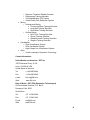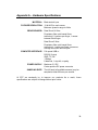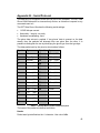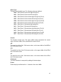
1
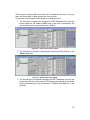
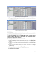
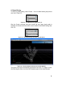
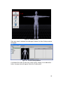
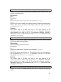
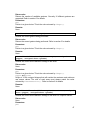
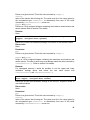
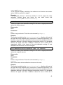
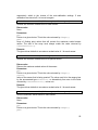
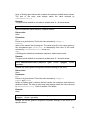
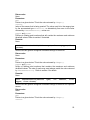
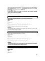
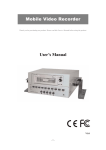
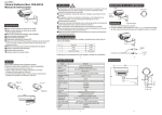
5DT Data Glove Ultra Series
User’s Manual
Fifth Dimension Technologies
www.5DT.com
5DT Data Glove Ultra
User’s Manual
Copyright © 2004 5DT (Fifth Dimension Technologies), All rights reserved. No part of
this manual, software or hardware may be copied, reproduced, translated or reduced
to any electronic medium or machine readable format without the written consent of
5DT (Fifth Dimension Technologies).
All trademarks and trade names are the respective property of their owners.
Version 1.1
October 2004
Table of Contents
1. Introduction............................................................................................................... 1
2. Setup and Installation............................................................................................... 2
2.1.
Package Contents ......................................................................................... 2
2.2.
Connecting the Glove .................................................................................... 2
3. Software Installation ................................................................................................. 3
3.1.
CD Contents .................................................................................................. 3
3.2.
Installed Software .......................................................................................... 4
4. Using GloveManager ............................................................................................... 5
4.1.
Starting GloveManager.................................................................................. 5
4.2.
Opening USB Gloves..................................................................................... 5
4.2.1
Scanning for Gloves ............................................................................... 5
4.2.2
Opening Gloves...................................................................................... 6
4.3.
Opening Serial and Wireless Gloves............................................................. 8
4.3.1
Scanning for Gloves ............................................................................... 8
4.3.2
Opening Gloves...................................................................................... 8
4.4.
The Graph View........................................................................................... 10
4.4.1
The Menu Bar....................................................................................... 11
4.4.2
Toolbar.................................................................................................. 12
4.4.3
Tab Bar ................................................................................................. 13
4.4.4
The Sensor Graphs .............................................................................. 13
4.4.5
The Sensor Info Box............................................................................. 14
4.4.6
The Status Bar...................................................................................... 16
4.5.
The Sensor Selection View.......................................................................... 16
4.6.
Glove Calibration ......................................................................................... 17
4.7.
Recording..................................................................................................... 19
5. Using the Gloves in Kaydara MOCAP™................................................................ 20
5.1.
Installation.................................................................................................... 20
5.2.
Opening the Glove....................................................................................... 20
5.3.
Opening Wireless Gloves ............................................................................ 21
5.4.
Calibration.................................................................................................... 23
5.5.
Model Binding .............................................................................................. 24
6. Using the SDK........................................................................................................ 27
6.1.
Introduction .................................................................................................. 27
6.2.
Using the SDK ............................................................................................. 27
6.3.
Sample Source Code................................................................................... 27
6.4.
Supported Gloves ........................................................................................ 28
6.5.
Sensor Mappings for the 5DT Data Glove 5 ............................................... 28
6.6.
Sensor Mappings for the 5DT Data Glove 16 and 14 Ultra......................... 29
6.7.
Gesture Definitions ...................................................................................... 30
6.8.
Auto-Calibration ........................................................................................... 32
7. Troubleshooting and Support................................................................................. 33
7.1.
General Troubleshooting ............................................................................. 33
7.1.1
Physical Connection Problems............................................................. 33
7.1.2
Software Connection Problems............................................................ 33
7.2.
Frequently Asked Questions (FAQ)............................................................. 33
7.3.
Support ........................................................................................................ 34
8. Warranty Information.............................................................................................. 35
8.1.
Thirty (30) Day Customer Satisfaction Guarantee ...................................... 35
8.2.
One (1) Year Product Warranty................................................................... 35
8.3.
Exclusions.................................................................................................... 35
8.4.
Warranty Claim Instructions......................................................................... 35
9. About 5DT .............................................................................................................. 37
Appendix A – Hardware Specifications...................................................................... 39
Appendix B – Serial Protocol ..................................................................................... 40
Appendix C – SDK Function Descriptions ................................................................. 42
1. Introduction
The 5DT Data Glove Ultra is a hand data motion capturing solution for
animation and virtual reality.
The 5DT Data Glove Ultra is the second generation of 5DT’s high-end data
glove and has been completely redesigned and optimized for the best
performance and ease of use. This glove measures finger flexure as well as the
abduction between the fingers. Finger flexure is measured at two places (1st
joint (knuckle), 2nd joint) on each finger.
Among the features of this kit are:
•
The glove is comfortable with an improved design for differently-sized
hands.
•
The accurate and sensitive sensors give a clean signal, minimizing the
need for additional filtering.
•
Diagnostic software is included with the capability to record hand data.
•
The package includes a plug-in for Kaydara MOCAP™.
•
The gloves’ functions and data are accessible via the 5DT Data Glove
SDK.
•
The glove data stream from the optional serial kit is an RS-232 data
stream with an open protocol allowing for various platform
implementations.
1
2. Setup and Installation
2.1. Package Contents
When first unpacking your glove, please ensure that all the parts are there. If
you are missing anything please contact 5DT or your reseller immediately.
The 5DT Data Glove Ultra consists of the following:
1. 5DT Data Glove Ultra (5 or 14 Sensor)
2. 5DT Data Glove Ultra Series USB cable
3. 5DT Data Glove CD
2.2. Connecting the Glove
Connect the glove to the PC as shown in Figure 1.
Figure 1 – Connecting the Glove to the PC.
You can use GloveManager to test the operation of the glove. Detail on this is
given in Section 4 of this manual.
2
3. Software Installation
Your package comes with a CD that contains documentation and utilities to help
you get up and running with the gloves as quickly as possible.
Most of the supplied programs and software are intended for 32-bit Windows,
and require Windows 98, ME, 2000, or XP.
The setup program should run when you insert the CD, but if it doesn’t, run the
program setup.exe in the install directory and follow the on-screen instructions.
When prompted, check the 5DT Data Glove Ultra box to install the software for
this product.
3.1. CD Contents
The CD contains the following directories:
…\Acrobat
This copy of Adobe® Acrobat® Reader will allow you to read the documentation.
…\DirectX
The CD-ROM also contains the redistributable version of DirectX 9.0. You will
need this if you want to run the DirectX implementations of the Glove Demos
(DirectX and OpenGL demos are supplied). To install DirectX 9.0, open the
folder and run dxsetup.exe.
…\Install
This contains the software installation files.
3
3.2. Installed Software
By default the setup program will install your files to the following directory:
C:\Program Files\5DT\Data Glove Ultra
The installation contains the following directories:
…\Demo
This folder contains the 3D glove demo. Click on GloveDemo.exe to start the
demo1.
…\Documents
This directory contains the electronic copy of this manual in pdf format and
application notes as they become available.
…\GloveManager
GloveManager is a program that allows you to test your gloves and access
advanced glove functions which may not be available in the plug-ins. More
detail on this is given in Section 4.
…\Plugins
This directory contains the plug-in for Kaydara MOCAP™ which replaces the
built-in Kaydara glove plug-in. More detail on this is given in Section 5.
…\SDK
This directory contains the 5DT Glove SDK files. These are described in detail
in Section 6.
1
The 3D glove demo will not function with the Data Glove Ultra USB.
4
4. Using GloveManager
The 5DT GloveManager is a useful tool accompanying the Data Glove which
may be used for the following:
•
Testing the 5DT Data Glove
•
Obtaining good calibrated values for the 5DT Data Glove
•
Logging data obtained from the 5DT Data Glove
Note: All images are shown for the Data Glove 14 Ultra. Images will differ
slightly for the Data Glove 5 Ultra.
4.1. Starting GloveManager
Start the program by running GloveManager.exe, which is installed in the
\Data Glove Ultra\GloveManager\ folder by default. The setup tab window will
appear (see below).
Figure 2 – The Setup Tab Window
4.2. Opening USB Gloves
4.2.1 Scanning for Gloves
button in the setup tab window causes GloveManager to
Clicking the
scan the USB for available gloves. This is useful if you have plugged in the
5
glove after starting GloveManager. Once the USB scan is complete the USB
device tree will be updated to show available gloves.
Figure 3 – Result of the USB Scan
As can be seen in Figure 3, the Port Scan has found two wireless gloves on
COM1. The right hand glove is plugged into Port A of the wireless transmitter
unit. The left hand glove is plugged into Port B.
4.2.2 Opening Gloves
A glove may by opened by clicking the
been selected in the device tree.
button after a USB glove has
Figure 4 – Selecting the Glove to be Opened
If the glove has been successfully opened the tab window will automatically
switch to the newly opened glove, as shown in Figure 5. Double-clicking on a
USB glove will also cause GloveManager to attempt to open the glove.
6
Figure 5 – GloveManager after the USB Glove is Successfully Opened
Clicking on the
tab will cause GloveManager to display the setup tab
window again. To open the second wireless glove, select it from the COM port
tree.
7
4.3. Opening Serial and Wireless Gloves
4.3.1 Scanning for Gloves
button in the setup tab window causes GloveManager to
Clicking the
scan the COM ports for available gloves. This is useful if you do not know on
which COM port your glove is connected to, or you simply want to scan for
available gloves. Once the COM port scan is complete the COM port tree will be
updated to show available gloves.
Figure 6 – Result of the Port Scan
As can be seen in Figure 6, the Port Scan has found two wireless gloves on
COM1. The right hand glove is plugged into Port A of the wireless transmitter
unit. The left hand glove is plugged into Port B.
4.3.2 Opening Gloves
A glove may by opened by clicking the
been selected in the COM port tree.
button after a COM port has
Figure 7 – Selecting the First Glove to be Opened
If the glove has been successfully opened the tab window will automatically
switch to the newly opened glove, as shown in Figure 8. Double-clicking on a
COM port will also cause GloveManager to attempt to open a glove on that
COM port.
8
Figure 8 – GloveManager after the First Glove is Successfully Opened
Clicking on the
tab will cause GloveManager to display the setup tab
window again. To open the second wireless glove, select it from the COM port
tree.
Figure 9 – Selecting the Second Glove to be Opened
Click on the
button again to open the second glove. If GloveManager
was successful in opening the second glove, a new glove tab window will
appear.
9
Figure 10 – The Tab Bar with Two Gloves Open
You may switch between open gloves by clicking on either of the Glove Tabs.
4.4. The Graph View
The following information fields are available in Graph View:
•
Menu bar
•
Toolbar
•
Tab bar – Allows you to tab between gloves
•
Sensor graph – A real-time graph of the glove sensor
•
Sensor name and values – Displays the sensor name and the following
real-time values (the amount of information displayed is dependent on
the resolution available):
o Raw sensor value [Value between 0 and 4095]
o Sensor dynamic range [Value between 0 and 4095]
o Scaled sensor value [Scaled value from 0 to 4095]
o Lower calibrated value [Value between 0 and 4095]
o Upper calibrated value [Value between 0 and 4095]
o Graph top value [Value between 0 and 4095]
o Current graph value [Value between 0 and 4095]
o Graph bottom value [Value between 0 and 4095]
•
Status bar – Displays status information, such as:
o Program status and information messages
o The packet rate
o An indication if recording is currently on
o An indication if auto calibration is currently on
o The model of the current glove
o The handedness of the current glove
o An indication if the current glove is wired or wireless
o The firmware version of the current glove
10
Menu bar
Toolbar
Tab bar
Sensor
graph
Sensor name
and values
Status bar
Figure 11 – Available Fields in Graph View
4.4.1 The Menu Bar
The following commands are available from the menu:
Item
Shortcut Description
File | New Recording
Ctrl+N
Creates a new recording file
File | Save Recording
Ctrl+S
Saves the current recording
File | Save Recording As…
File | Close Current Glove
Saves the current recording as a new file name
Alt+C
Closes the currently visible glove
File | Exit
Exits GloveManager
View | Toolbar
Shows/Hides the Toolbar
View | Status Bar
Shows/Hides the Status Bar
View | Show View Setup
V
Toggles between the sensor selection and the graph view
View | Show Scaled Graphs
S
Shows/Hides the Scaled Graphs
View | Show Raw Graphs
X
Shows/Hides the Raw Graphs
Recording | Record
Ctrl+R
Toggles recording of glove data on or off
11
Item
Shortcut Description
Calibration | Auto Calibration
A
Toggles between auto and manual calibration
Calibration | Manual Calibration
M
Toggles between auto and manual calibration
Calibration | Reset Calibration
R
Resets the auto calibration values, and turns auto calibration on
Calibration | Load Calibration Values Alt+O
Load the calibration values from file, turns auto calibration off
Calibration | Save Calibration Values Alt+S
Save the current calibration values to file
About | About GloveManager…
Displays information about GloveManager
Table 1 – Menu Commands Available in GloveManager
4.4.2 Toolbar
The following buttons are available on the toolbar:
Icon
Shortcut Description
Ctrl+N
Creates a new recording file
Ctrl+S
Saves the current recording
Ctrl+R
Toggles recording of glove data on or off
X
Shows/Hides the raw graphs
S
Shows/Hides the scaled graphs
R
Resets the auto calibration values, and turns auto calibration on
Alt+O
Load the calibration values from file, turns auto calibration off
Alt+S
Save the current calibration values to file
A
Toggles between auto and manual calibration
M
Toggles between auto and manual calibration
V
Toggles between the sensor view setup and the graph view
Alt+C
Closes the currently visible glove
Table 2 – Buttons Available on the GloveManager Toolbar
12
Some items may me disabled when no glove is open.
4.4.3 Tab Bar
The tab bar allows you to switch between the Setup view and the currently open
gloves. The blue dot on the tab icon indicates a wireless glove.
Figure 12 – The Tab Bar
4.4.4 The Sensor Graphs
The sensor graph is a graphical representation of the data from the sensors as
it arrives. Two graph representations can be shown:
The scaled graph (showing the values scaled between 0 and 4095)
The raw graph (showing the raw values between 0 and 4095)
4.4.4.1 Scaled Graph
The scaled graph shows the scaled version of the sensor value, normalized
between 0 and 1. The default color for this graph is blue.
Figure 13 – The Scaled Graph
4.4.4.2 Raw Graph
The raw graph represents the raw sensor value coming from the glove.
Additional to the actual graph of the raw values (drawn in red by default), the
upper (drawn in green by default) and lower calibration (drawn in orange by
default) values are also plotted, as shown in Figure 14.
Upper calibration value
Raw sensor value
Lower calibration value
Figure 14 – The Raw Graph
13
4.4.4.3 Graph Zooming
You may zoom into a graph by simply clicking on it, as illustrated below:
Left click
Figure 15 – An Illustration of the Zoom Procedure
The zoomed view gives you a more detailed view of the graph, and allows you
to do fine-tuning of the calibration value.
4.4.5 The Sensor Info Box
The sensor info box provides the following information (see Figure 16):
•
Raw sensor value [Value between 0 and 4095]
•
Sensor dynamic range [Value between 0 and 4095]
•
Scaled sensor value [Scaled value from 0 to 4095]
•
Lower calibrated value [Value between 0 and 4095]
•
Upper calibrated value [Value between 0 and 4095]
•
Graph top value [Value between 0 and 4095]
•
Current graph value [Value between 0 and 4095]
•
Graph bottom value [Value between 0 and 4095]
14
Sensor name Raw value
Graph top
value
Scaled value
Current graph
value
Graph bottom
value
Lower calibration value
Upper calibration value
Dynamic range value
Figure 16 – The Sensor Info Box
The upper and lower calibration values may be fine-tuned by adjusting the
minimum and maximum values of the dynamic range. These values are
automatically adjusted during auto calibration. Please note that the calibration
mode is automatically switched to manual calibration during fine-tuning.
The sensor info box has three levels of detail, depending on the pixel resolution
available to GloveManager. The highest level of detail is shown in Figure 16. As
the pixel resolution decreases, the second level of detail is switched to, as in
Figure 17. The value shown next to the sensor name is:
•
the current scaled value (when scaled graphs are visible)
•
the current raw value (when raw graphs are visible)
Figure 17 – The Second Level of Detail of the Sensor Info Box.
If the pixel resolution is decreased more, only the sensor name and current
graph value are shown.
Figure 18 – The Lowest Level of Detail of the Sensor Info Box.
15
4.4.6 The Status Bar
The status bar displays various program and glove related information,
including:
•
Program status and information messages
•
The packet rate
•
An indication if recording is currently on
•
An indication if auto calibration is currently on
•
The model of the current glove
•
The handedness of the current glove
•
An indication if the current glove is wired or wireless
•
The firmware version of the current glove
Recording
indicator
Program status/
Information messages
Current packet rate
Glove
name
Glove
handedness
Auto calibration indicator
Glove firmware
version
Glove Wired /
Wireless indicator
Figure 19 - The Status Bar
4.5. The Sensor Selection View
The sensor selection view may be obtained by clicking the
button on the
toolbar, by selecting the View | Show View Setup option from the menu or by
pressing the V shortcut key. The view is shown in Figure 20.
The hand and sensor image on the left allows you to select sensors to be used
during recording. Selecting none means that this glove will not be used during
the recording process.
The hand and sensor image on the right allows you to select specific sensors to
be shown in graph view. Please note that the program will not allow you to
display zero sensors.
Clicking the
,
,
,
,
, or
buttons causes the corresponding sensors to be selected or deselected. You
may also select or deselect a sensor by clicking on it ( or ).
16
or
buttons, by
You may go back to graph view by clicking on the
selecting the View | Show View Setup option from the menu or by pressing the
V shortcut key.
4.6. Glove Calibration
Figure 20 – The Sensor Selection View
Glove calibration values may be loaded from file by clicking the
button, by
selecting the Calibration | Load Calibration Values menu option, or by using
the Alt+O shortcut key. The file open dialog box will appear.
17
Figure 21 – The File Open Dialog for Calibration Files
Select a calibration file (extension .cal) and click on the
open the file.
button to
Glove calibration values may be saved to file by clicking the
button, by
selecting the Calibration | Save Calibration Values menu option, or by using
the Alt+S shortcut key. The file save dialog box will appear.
18
Figure 22 – The File Save Dialog for Calibration Files
Type in your file name and click the
button to save the calibration
values to file. The file format is also compatible with the 5DT Data Glove SDK.
4.7. Recording
The incoming glove data may be recorded by clicking the
button, by
selecting the Recording | Record menu option, or by using the Ctrl+R shortcut
key. This will cause GloveManager to record the latest raw and scaled values at
a fixed rate of 60 Hz. Only the sensors selected for recording in the sensor
setup view (see section 4.5) will be recorded. These values are recorded in
memory and will be lost unless saved to file.
The values may be saved to file, by clicking the
button, by selecting the
File | Save or File | Save As… menu option, or by using the Ctrl+S shortcut
key. Currently only the CSV (Comma Separated Values) file format is
supported.
19
5. Using the Gloves in Kaydara MOCAP™
5.1. Installation
To install the driver, follow the steps given below.
1. Copy the file ordevice5dt.dll to the [MOCAP]\bin\plugins directory.
2. Make sure that the 5DT Glove driver is installed – specifically fglove.dll
should be installed in the Windows\System folder.
3. Run MOCAP.
4. Verify that the driver is installed by clicking on the Devices tab in the asset
browser. The installed driver should be visible as shown in the red
rectangle as shown in Figure 23 below.
Figure 23 - Verifying that the 5DT Data Glove Plugin has been Installed
5.2. Opening the Glove
From the device pane of the Asset Browser, create a glove in Kaydara by
clicking and dragging the 5DT DataGlove icon to the viewer window (see Figure
24).
20
Figure 24 - Clicking and Dragging the 5DT DataGlove Icon to Create a New Glove
In the navigator pane, click on the newly created glove. The following window
will appear:
Figure 25 - The Glove Control Pane
If you know which port the glove is connected to, select it from the ports dropdown list.
If you are unsure as to which port your glove is connected to you may click on
the Rescan Ports button. The driver will then scan the USB and all COM ports
for available gloves and update the Ports drop-down list. The progress of the
scan process is shown in the status bar in the Viewer window. Please note that
the scan process may take a while.
Once the correct port has been selected, click on the Online button. If the red
button turns green, a successful connection has been made.
5.3. Opening Wireless Gloves
The new 5DT Data Glove Ultra Wireless Kit uses one COM port for receiving
data from both gloves connected to the transmitter unit. The driver handles this
transparently by allowing you to open two gloves on the same port. Only once
21
the first glove is opened will the second one be opened by the driver. You may
open and close either of these gloves any time you wish.
The process of opening two wireless gloves is illustrated next:
1. The first glove is created (by dragging the 5DT DataGlove icon from the
device pane into the viewer window) and a port scan is performed. We
can see that there is a glove present on COM1-A.
Figure 26 – Result of the First Port Scan
2. The first glove is opened by selecting the correct port and clicking on the
Online check box.
Figure 27 – Glove A has been opened
3. The second glove is created by dragging the 5DT DataGlove icon from the
device pane into the viewer window. The driver automatically picks up that
another wireless glove may be opened on COM1-B and adds this to the
ports list.
22
Figure 28 - Result of the Second Port Scan
4. The second glove is opened by selecting the correct port and clicking on
the Online check box.
Figure 29 - Glove B has been Opened
5.4. Calibration
You may use auto calibration to calibrate the glove, but it is recommended that
you use the pre-defined calibration steps.
To use auto calibration, click on the Auto Calib button. The button text will
change to Click to Stop. Once you are satisfied with the calibration values,
click the button again to stop calibrating.
The following calibration process is recommended.
1. Hold your hand in a relaxed, open position, and click on the Relax Open
button.
2. Open all of your fingers as wide as possible and click on the Wide Open
button.
3. Close all of your fingers (except your thumb) and click on the Finger
Close button.
4. Close your thumb and click on the Thumb Close button.
5. Calibration is now complete.
23
5.5. Model Binding
To create a model binding, select Create… from the Model binding drop-drown
menu as in Figure 30.
Figure 30 - The Model Binding Drop-down List
After the Create command has been issued the wire frame hand model is
created in the viewer and the model’s name is added to the Model binding dropdown list.
Figure 31 - The Model Binding Drop-down List with Hand
Figure 32 – The Glove Model as Shown in the Viewer Window
This glove can now be automatically connected to an actor. To create an actor,
click and drag the Actor icon from the Characters pane in the Asset Browser.
24
Figure 33 – Creating an Actor
If the actor asset is selected in the Navigator window, the Actor Settings window
will appear.
Figure 34 – The Actor Settings Window
If no Marker Set exists for this actor create one by clicking on the MarkerSet…
button. A popup menu will appear. Select the Create option.
25
Figure 35 – Creating a Marker Set
Once a Marker Set has been selected, select the hand marker to which the
glove should be referenced. Drop the root of the glove device (under the Scene
branch) into the Glove Reference in the Model column. Click on the Active
checkbox to make the actor active (real-time animations are shown).
Figure 36 – Assigning a Glove Reference to a Marker Set
26
6. Using the SDK
6.1. Introduction
The 5DT Data Glove SDK provides access to the 5DT range of data gloves at
an intermediate level.
The Windows 98/NT/Me/XP version is provided in the form of a C/C++ header
(.h) file, a Microsoft Visual C++ library (.lib) file and a dynamic link library (.dll)
file.
The SDK functionality includes:
•
Multiple instances
•
Easy initialization and shutdown
•
Basic (raw) sensor values
•
Scaled (auto-calibrated) sensor values
•
Calibration functions
•
Basic gesture recognition
•
Cross-Platform Application Programming Interface
The SDK functions are described in detail in Appendix C.
6.2. Using the SDK
The 5DT Data Glove Driver is easy to implement using the following guidelines:
1. Make sure that the header file fglove.h, the library file fglove.lib
and the dynamic link library file fglove.dll reside in the current
(application) directory, or somewhere that they can be found. The file
fglove.dll may be copied into your Windows system directory.
2. Include the header file fglove.h in the application where necessary.
3. Add the library file fglove.lib to the link process.
There is also a debug version of the driver (fgloved.lib, fgloved.dll)
which outputs debug messages to the debugger.
6.3. Sample Source Code
In the samples directory, there is sample source code that makes use of the
glove SDK. Both a console application as well as a Microsoft® Visual Studio® 6
project is included.
27
6.4. Supported Gloves
The glove SDK supports all 5DT Data Gloves. The current version implements
18 possible sensors, and includes the roll and pitch sensors of the 5DT Data
Glove 5. The driver attempts to map values to all sensor outputs. If it is unable
to do so the sensor value defaults to a sensible value. This value can be
adjusted by forcing a specific value. To the application programmer the driver
therefore appears the same regardless of the type of glove that is connected.
6.5. Sensor Mappings for the 5DT Data Glove 5
The sensors on the 5DT Data Glove 5 are positioned as in Figure 37.
E
D
C
F
B
G
Top of hand
Right-handed glove
A
Tilt sensor
Figure 37 - Sensor Positions for the 5DT Data Glove 5
Sensor Driver Sensor
Index
A
0,1*
B
3,4*
C
6,7*
D
9,10*
E
12,13*
F
16+
G
17+
Description
Thumb flexure
Index finger flexure
Middle finger flexure
Ring finger flexure
Little finger flexure
Pitch angle of tilt
sensor
Roll angle of tilt sensor
Table 3 - Sensor Mappings for the 5DT Data Glove 5 and 5DT Data Glove 5 Ultra
*
Both these driver sensor indices will return the same value when the 5DT
Data Glove 5 or Data Glove 5 Ultra is used.
+
Not available on the Data Glove 5 Ultra.
28
6.6. Sensor Mappings for the 5DT Data Glove 16 and 14 Ultra
The sensors on the 5DT Data Glove 16 are positioned as in Figure 38.
13
12
10
7
9 11
8
6
5
4
3
2
0
1
Figure 38 – Sensor Mappings for the 5DT Data Glove 16 and 5DT Data Glove 14 Ultra
Sensor Driver Sensor
Index
0
0
1
1
2
2
3
3
4
4
5
5
6
6
7
7
8
8
9
9
10
10
11
11
12
12
13
13
Description
Thumb flexure ( lower joint )
Thumb flexure ( second joint )
Thumb-index finger abduction
Index finger flexure ( at knuckle )
Index finger flexure ( second joint )
Index-middle finger abduction
Middle finger flexure ( at knuckle )
Middle finger flexure ( second joint )
Middle-ring finger abduction
Ring finger flexure ( at knuckle )
Ring finger flexure ( second joint )
Ring-little finger abduction
Little finger flexure ( at knuckle )
Little finger flexure ( second joint )
Table 4 – Sensor Mappings for the 5DT Data Glove 16 and 5DT Data Glove 14 Ultra
29
6.7. Gesture Definitions
The currently defined set of gestures is comprised of binary open/close
configurations of the fingers excluding the thumb. There are 24 = 16 such
possible combinations. Gesture number 0 is defined as all the fingers (excluding
the thumb) being closed, and gesture number 15 as all the fingers open. The
index finger indicates the least significant bit. For example, the index finger
point gesture will therefore be number 1, and the little finger point gesture
number will be 8. An invalid (unrecognizable) gesture is defined as the value -1.
A scaled sensor value of higher than the upper threshold setting will indicate a
closed finger, while a scaled sensor value of lower than the lower threshold
setting will indicate an open finger. A value in-between is invalid and will result
in an invalid gesture. In the case of multiple finger joint angle measurements,
the maximum of the individual joint sensor values is taken to obtain a closed
gesture and the minimum to obtain an open gesture. Closed gestures take
precedence, in other words, bending only one joint of a finger will count as a
closed gesture.
Finger:
5DT Data Glove 5
sensor:
5DT Data Glove 16 &
14 Ultra sensor:
Driver sensor index:
Gesture
Number
0
1
2
3
4
5
6
7
8
9
10
11
12
13
14
15
Little
Ring
Middle
Index
E
D
C
B
12,13
9,10
6,7
3,4
12,13#
9,10#
6,7#
3,4#
Flexure (0=flexed, 1=unflexed)
0
0
0
0
0
0
0
0
1
1
1
1
1
1
1
1
0
0
0
0
1
1
1
1
0
0
0
0
1
1
1
1
0
0
1
1
0
0
1
1
0
0
1
1
0
0
1
1
0
1
0
1
0
1
0
1
0
1
0
1
0
1
0
1
Gesture Description
Fig.
Fist
Index finger point
Middle finger point
Two finger point
Ring finger point
Ring index point
Ring middle point
Three finger point
Little finger point
Index and little finger
i point
Little middle
16.0
16.1
16.2
16.3
16.4
16.5
16.6
16.7
16.8
16.9
16.1
0
16.1
1
16.1
2
16.1
3
16.1
4
16.1
Not ring finger point
Little ring point
Not middle finger point
Not index finger point
Flat hand
Table 4 - Gesture Definition Scheme as Implemented for the 5DT Data Glove SDK
#
When the 5DT Data Glove 5 is used, both these driver sensor indices will
return the same value.
30
0) Fist
1) Index finger point
2) Middle finger point
3) Two finger point
4) Ring finger point
5) Ring-index finger point
6) Ring-middle finger
point
7) Three finger point (or
not little finger point)
8) Little finger point
9) Index and little finger
point
10) Little-middle finger
point
11) Not ring finger point
12) Little-ring finger point
13) Not middle finger
point
14) Not index finger point
15) Flat hand
Figure 16 - Gesture Illustrations
When the 5DT Data Glove 16 or 5DT Data Glove 14 Ultra is used, the driver
sensor indices will return different values. The maximum of the two values will
31
be used to test for a flexed (closed) gesture, and the minimum value of the two
will be used to test for an unflexed (open) gesture.
6.8. Auto-Calibration
The driver can provide sensor outputs in an automatic, linearly calibrated
fashion. During every update, the raw value read from the sensor is compared
to the current minimum and maximum raw values (rawmin and rawmax) as set by
the
functions
fdSetCalibrationAll(),
fdSetCalibration()or
fdResetCalibration(). If the current minimum and maximum values are
exceeded, they are overwritten. The upper and lower calibration values are
therefore continuously pushed "outwards". The normalized output is given by
the first order equation
out =
rawval − rawmin
.Max,
rawmax − rawmin
(F-1)
which is in [0...Max]. The value of Max is set by the functions
fdSetSensorMaxAll()and fdSetSensorMax(). Doing a few flexing
movements with the hand quickly sets the operating values for rawmin and
rawmax, and calibrates the glove.
The auto-calibration process can be ignored by simply regarding only the raw
sensor outputs. It would be up to the application developer to provide a suitable
calibration process.
Note that calibration is mandatory, especially with the high-end gloves
which contain no hardware calibration possibilities.
32
7. Troubleshooting and Support
The following information is provided to help you diagnose any problems that
may be encountered with your 5DT Data Glove Ultra or 5DT Data Glove Ultra
Wireless Kit. Please consult this section before contacting your supplier.
7.1. General Troubleshooting
If the glove is not working at all, please work through the physical connection
problems section of the troubleshooting procedure to identify the source of the
problem.
7.1.1 Physical Connection Problems
1. Check that power is connected to the receiver as well as to the wireless
data transmitter. There should be a green light on the transmitter when
power is applied.
2. Check that the glove is connected to the right port. Try to connect the
glove to another port and try again.
3. Check all the connections. Section 2.2 has information on how to
correctly connect the system.
4. Check that the port is working. Try connecting another device, for
example an external modem.
If the 5DT Data Glove is recognized by your computer but not connecting
properly, proceed directly to the software connection problems section.
7.1.2 Software Connection Problems
Run GloveManager from the start menu. Check which COM ports are available
by looking at the list in Figure 3. Remember that not all available ports will be
physically connected to a socket on the back of your computer. Some ports may
be unavailable because other programs have already taken control of the ports.
Examples are mouse drivers and fax or communication programs.
7.2. Frequently Asked Questions (FAQ)
Q
My gloves are connected to COM2, but Glove Manager reports that this
port is not available.
A
There may be a mouse driver, or other program that has already opened
that port. Once a program or driver has opened a COM port, no other
program will be able to access that port until the first one closes.
Q
Is it possible to use the 5DT Data Glove Ultra in a LINUX environment?
A
No, the Linux version of the SDK does not support the 5DT Data Glove
Ultra, but check our website regularly for updates.
33
Q
Can I use four (or more) serial gloves on one machine at the same time?
A
5DT just loves people like you! The number of gloves is limited by the
number of serial ports on your computer. Multiport cards are available
that have up to eight serial ports on them and you only need one serial
port per wireless pair. It is also possible to obtain a USB (Universal Serial
Bus) device that has many RS 232 serial ports on it.
Q
When I flex a finger, the output does not change but stays at the
maximum value. What is the problem?
A
In this case it is possible that one of the fibers has failed. The glove will
then have to be returned to the supplier (or 5DT) for repairs.
7.3. Support
If you experience problems or have complaints, suggestions or other
comments, please feel free to contact your supplier (preferably via e-mail).
Please have the following information available, or include it in your written
correspondence:
1. Computer processor make and model (e.g. Pentium IV 3.2GHz)
2. Operating system and version
3. The symptoms of the problem and what was happening when the
problem occurred
4. Can you reproduce the problem easily? Describe how
5. Actions taken by yourself to solve the problem
Please feel free to contact 5DT directly. Our contact details are available in
Section 9.
Your feedback helps make this a truly great product.
34
8. Warranty Information
8.1. Thirty (30) Day Customer Satisfaction Guarantee
If, for any reason, you are disappointed with this product, please contact your
supplier. If you are not completely satisfied, you will be granted a full refund
once the product is returned undamaged. Unfortunately, shipping costs cannot
be refunded.
8.2. One (1) Year Product Warranty
5DT warrants to the original purchaser of the 5DT Data Glove 14 Ultra Wireless
Kit that it will be free of defects in materials and workmanship for a period of
one year from the original date of purchase. During the warranty period, 5DT
will repair or replace (with a reconditioned unit) components that are defective.
8.3. Exclusions
The above warranty is provided for private use only and shall not apply to any
commercial use of the product, including (but not limited to):
•
•
Location based entertainment (LBE) applications
Trade show demonstrations
This warranty shall not apply to defects resulting from the following:
•
•
Misuse
Improper or inadequate maintenance
•
Unauthorized modification
8.4. Warranty Claim Instructions
Please use the following procedure if you require warranty service:
1. Contact your supplier to determine if you need to return the product. If
your supplier is unable to determine this, contact 5DT directly. Do not
return a product to your supplier or to 5DT without first contacting them.
2. Your supplier (or 5DT) will issue you with a Return Material Authorization
(RMA) number. Do not return a product to your supplier or to 5DT without
an RMA number.
3. Pack the items to be returned securely using the original packaging
material (if possible).
4. Please enclose the following:
•
Your original sales bill
•
Name, address, contact telephone/fax numbers
•
E-mail address
•
Reason for returning the item
•
RMA number
35
5. Mark your shipping container with the RMA number to expedite handling
at your supplier or at 5DT.
6. Ship prepaid to your supplier or to 5DT.
7. When completing customs or courier documentation, please clearly
indicate: "Unit returned for repairs under warranty".
5DT is not responsible for any damage that may occur during shipping.
Shipping charges to 5DT are your responsibility. COD shipments will not be
accepted by 5DT.
36
9. About 5DT
5DT <Fifth Dimension Technologies> is a high technology company specializing
in Virtual Reality (VR). 5DT develops, produces and distributes affordable virtual
reality hardware, software and systems. 5DT can also develop custom systems
for all your VR needs.
5DT's focus is Virtual Reality Training Systems and Virtual Reality Peripherals.
The Virtual Reality hardware currently produced by 5DT includes:
•
•
•
•
•
•
•
•
•
•
•
•
5DT Data Glove 5 (Right and left)
5DT Data Glove 5-W (Wireless, right and left)
5DT Data Glove 5 Ultra
5DT Data Glove 16 (Right and left)
5DT Data Glove 16-W (Wireless, right and left)
5DT Data Glove 14 Ultra
5DT Data Glove 14 Ultra Wireless Kit
5DT Data Glove MRI
5DT Virtual Binoculars
5DT Head Mounted Display (HMD)
5DT Virtual Binoculars
5DT Motion Base
VR Software Systems developed by 5DT include:
•
•
•
•
•
Automotive
o Driving Training Simulator Series
o Road Safety Training System
Aviation
o Airspace Visualizer
o Air Traffic Control (ATC) Training Simulator
o Experimental Avionics Testbed
o Unmanned Aerial Vehicle (UAV) Training Simulator
Defense
o Air Defense Training Simulator
o Fiber Optic Guided Missile Training System and Training
Simulator
o Rocket Launcher Training Simulator
o Stand-Off Weapon Training Simulator and Visualizer
High Voltage
o High Voltage Line Inspection Logging System
o High Voltage Line Inspection Training Simulator
o High Voltage Line Inspection Training System (CBT)
o High Voltage Line Repair Training System
o High Voltage Line Visualization System
o High Voltage Yard Training Simulator
Medical
o Bronchoscope Training Simulator
37
•
•
•
o Exposure Treatment Phobia Simulator
o Gastroscope Training Simulator
o Tele-Rehabilitation (TR) System
o Virtual Reality Pain Distraction System
Mining
o Underground Mining
• Continuous Miner Training Simulator
• Long Wall Training Simulator
• Roof Bolter Training Simulator
o Surface Mining
• Haul Truck Training Simulator
• Shovel Training Simulator
• Wheeled Loader Training Simulator
• Dragline Training Simulator
Visualization
o Flight Visualization System
o Flow Visualization System
o High Voltage Line Visualization System
Other
o Virtual Landscape Generation Technology
Contact Information
United States and Americas - 5DT Inc
15375 Barranca Pkwy, G-103
Irvine, CA 92618, USA
United States of America
Tel:
+1 949 450-9044
Fax:
+1 949 450-9045
e-mail:
[email protected]
Web:
www.5dt.com
Rest of World - 5DT (Fifth Dimension Technologies)
25 De Havilland Crescent, P.O. Box 5
Persequor Park, 0020
South Africa
Tel:
+27 12 349 2690
Fax:
+27 12 349 1404
E-mail:
[email protected]
Web:
www.5dt.com
38
Appendix A – Hardware Specifications
MATERIAL: Black stretch lycra
FLEXURE RESOLUTION: 12-bit A/D for each sensor
Minimum dynamic range is 8-bits
BEND SENSORS: Data Glove 14 Ultra:
Proprietary fiber optic based flexor
technology. 2 sensors per finger, 1 sensor
between each finger
Data Glove 5 Ultra:
Proprietary fiber optic based flexor
technology. 1 sensor per finger, measures
average of knuckle and first joint.
COMPUTER INTERFACE: Full-speed USB or
RS 232 (3-wire)
GND, TX, RX
115kbps
8 data bits, 1 stop bit, no parity
POWER SUPPLY: Maximum 5 V DC
Center positive DC power connector
SAMPLING RATE: The full hand (all available sensors) may be
sampled at least 60 times per second.
At 5DT we constantly try to improve our products As a result, these
specifications are subject to change without prior notice.
39
Appendix B – Serial Protocol
The data glove is connected to the RS-232 port of the computer. The 5DT Data
Glove Ultra Wireless Kit is a transmit-only device, as it does not respond to any
commands sent to it.
The 5DT Data Glove Ultra has the following serial settings:
•
115200 bits per second
•
8 data bits, 1 stop bit, no parity
•
Hardware handshaking: none
The glove data arrives in packets. If two gloves’ data is present on the data
stream, then the packets will alternate from one glove then the other. It is
possible to distinguish the two by identifying the glove type from the type byte.
The data packet sent by the glove is structured as follows:
Byte No.
Byte
Byte No.
Byte
1
Start
17
10Lu | 10Ll
2
Type Byte
18
11Hl |11Lu
3
Version
19
11Ll
4
1Ll
| 2Hl
20
12Lu |12Ll
5
2Lu
| 2Ll
21
13Hl |13Lu
6
3Hl
| 3Lu
22
13Ll
7
3Ll
| 4Hl
23
14Lu |14Ll
8
4Lu
| 4Ll
24
15Hl |15Lu
9
5Hl
| 5Lu
25
15Ll
10
5Ll
| 6Hl
26
16Lu |16Ll
11
6Lu
| 6Ll
27
Checksum
12
7Hl
| 7Lu
28
Footer
13
7Ll
| 8Hl
14
8Lu
| 8Ll
15
9Hl
| 9Lu
16
9Ll
| 10Hl
|12Hl
|14Hl
|16Hl
Table 5 - 5DT Data Glove 14 Ultra Packet Description
The bytes of the packet are defined as follows:
Header
Packet start byte defined as the ‘<’ character. Hex value: 0x3c
40
Glove Type
The glove type identifier byte. The following values are defined:
0x00 – Data Glove14 Ultra wired right hand glove
0x01 – Data Glove14 Ultra wired left hand glove
0x02 – Data Glove14 Ultra wireless right hand glove (Port A)
0x03 – Data Glove14 Ultra wireless left hand glove (Port A)
0x06 – Data Glove14 Ultra wireless right hand glove (Port B)
0x07 – Data Glove14 Ultra wireless left hand glove (Port B)
0x10 – Data Glove 5 Ultra wired right hand glove
0x11 – Data Glove 5 Ultra wired left hand glove
0x12 – Data Glove 5 Ultra wireless right hand glove (Port A)
0x13 – Data Glove 5 Ultra wireless left hand glove (Port A)
0x16 – Data Glove 5 Ultra wireless right hand glove (Port B)
0x17 – Data Glove 5 Ultra wireless left hand glove (Port B)
Version
The firmware version byte. The upper nibble (Vmaj) represents the version
major, the lower nibble (Vmin) represents the version minor.
xHl
The upper four bits of the 12-bit sensor value, or the lower nibble of the MSB of
the 12-bit sensor value.
xLh
The middle four bits of the 12-bit sensor value, or the upper nibble of the LSB of
the 12-bit sensor value.
xLl
The lower four bits of the 12-bit sensor value, or the lower nibble of the LSB of
the 12-bit sensor value.
Checksum
The 8-bit checksum is computed by adding all the data bytes.
Footer
Packet stop byte defined as the ‘>’ character. Hex value: 0x3e
41
Appendix C – SDK Function Descriptions
The following functions are available in the SDK:
fdGlove *fdOpen(char *pPort)
Initializes the glove device on the specified port.
Return value
Returns a pointer to the glove device (fdGlove *). NULL is returned if an error
occurred.
Parameter
pPort
Pointer to a zero terminated ASCII string containing the name of the
communication port. Valid values on Windows range from "COM1" to "COM8".
Unix/Linux port names will differ.
Remarks
Do not attempt to alter the contents of the returned pointer directly, use the
functions provided instead.
int fdClose(fdGlove *pFG)
Frees the glove device and communications port.
Return value
Returns nonzero if successful, zero if an error occurred.
Parameters
pFG
Pointer to a glove device. This is the value returned by fdOpen().
Remarks
It is important to call this function when you are finished using the glove.
int fdScanUSB(unsigend short *aPID, int &nNumMax)
Scans the USB for available gloves.
Return value
Returns the number of gloves found during the scan.
Parameters
aPID
Pointer an unsigned short array of length nNumMax. The USB Product IDs
(PIDs) of the gloves found are returned in this array. The following PIDs are
defined:
DG14U_R – Data Glove 14 Ultra Right-hand
DG14U_L – Data Glove 14 Ultra Left-hand
DG5U_R – Data Glove 5 Ultra Right-hand
DG5U_L – Data Glove 5 Ultra Left-hand
42
nNumMax
The length of the aPID array. The number of gloves found is also returned in
this parameter.
Remarks
None.
int fdGetGloveHand(fdGlove *pFG)
Obtains the handedness (left or right handed) of the glove.
Return value
Returns either FD_HAND_LEFT or FD_HAND_RIGHT, as defined by the
enumerated type EfdGloveHand.
Parameters
pFG
Pointer to a glove device. This is the value returned by fdOpen().
Remarks
None.
int fdGetGloveType(fdGlove *pFG)
Obtains the type of the currently connected glove.
Return value
Returns one of FD_GLOVENONE, FD_GLOVE7, FD_GLOVE7W, FD_GLOVE16
FD_GLOVE16W, FD_GLOVE14U, FD_GLOVE14UW, or FD_GLOVE14U_USB, as
defined by the enumerated type EfdGloveTypes.
Parameters
pFG
Pointer to a glove device. This is the value returned by fdOpen().
Remarks
FD_GLOVE7 and FD_GLOVE7W refer to the original 5+2 (tilt angles) sensor glove
(5DT Data Glove 5). The W suffix indicates a wireless model. FD_GLOVE16 and
FD_GLOVE16W refer to the Data Glove 16. FD_GLOVE14, FD_GLOVE14W, and
FD_GLOVE14_USB refer to the Data Glove 14 Ultra. The USB suffix refers to the
Universal Serial Bus interface. In order to accommodate all glove types the
fdGetNumSensors() function currently returns 18 sensors. The additional two
sensors are defined as the original tilt angles that are not present in the 16sensor glove. See the description of fdGetNumSensors()for more details.
int fdGetNumSensors(fdGlove *pFG)
Obtains the number of available sensors values the driver can make available.
Return value
43
Returns the number of sensors. Currently it is fixed at 18, but future driver
releases may differ.
Parameters
pFG
Pointer to a glove device. This is the value returned by fdOpen().
Remarks
Although the 5-sensor glove can measure only average flexure, the driver will
attempt to fill in missing values. The number of sensors returned can therefore
be of a higher dimension. The enumerated type EfdSensors defines the
finger mapping for each sensor.
void fdGetSensorRawAll(fdGlove *pFG, unsigned short *pData)
Obtains the most recent raw sensor values from the currently connected glove.
Return value
None.
Parameters
pFG
Pointer to a glove device. This is the value returned by fdOpen().
pData
Pointer to an array of 16-bit integers that will contain the raw sensor values. The
size of the array must always match the value returned by
fdGetNumSensors().
Remarks
Currently the raw sensor samples are all 12 bit unsigned values. The range is
therefore from 0 to 4095. Note that this is not the dynamic range of the sensors.
There can be severe offset values associated with each sensor. The
enumerated type EfdSensors defines the finger mapping for each sensor.
unsigned short fdGetSensorRaw(fdGlove *pFG, int nSensor)
Obtains the most recent raw sensor value for a specific sensor from the
currently connected glove.
Return value
Returns a 16-bit integer. See fdGetSensorRawAll() for details.
Parameters
pFG
Pointer to a glove device. This is the value returned by fdOpen().
nSensor
Index of the sensor that is being set. The value must lie in the range given by
the enumerated type EfdSensors, or alternatively from zero to the value
returned by fdGetNumSensors() minus one.
Remarks
44
The enumerated type EfdSensors defines the finger mapping for each
sensor.
void fdSetSensorRawAll(fdGlove *pFG, unsigned short *pData)
Forces the raw value for all the sensors.
Return value
None.
Parameters
pFG
Pointer to a glove device. This is the value returned by fdOpen().
pData
Pointer to an array of 16-bit integers that will contain the raw sensor values. The
size of the array must always match the value returned by
fdGetNumSensors().
Remarks
Currently the raw sensor samples are all 12 bit unsigned values. The range is
therefore from 0 to 4095. The enumerated type EfdSensors defines the finger
mapping for each sensor. Forcing a sensor value will result in a raw and scaled
output other than the default zero. Values that can be mapped will be
overwritten, rendering the forced value void.
void fdSetSensorRaw(fdGlove
short nRaw)
*pFG,
int
nSensor,
unsigned
Forces the raw value for a specific sensor.
Return value
None.
Parameters
pFG
Pointer to a glove device. This is the value returned by fdOpen().
nSensor
Index of the sensor that is being set. The value must lie in the range given by
the enumerated type EfdSensors, or alternatively from zero to the value
returned by fdGetNumSensors() minus one.
nRaw
16 bit raw value of the sensor. If the sensor is unmapped, the scaling
calculations will proceed as normal.
Remarks
The enumerated type EfdSensors defines the finger mapping for each
sensor. This function is only useful for sensors that cannot be mapped by a
specific hardware device. Forcing a sensor value will result in a raw and scaled
output other than the default zero. Values that can be mapped will be
overwritten, rendering the forced value void.
45
void fdGetSensorScaledAll(fdGlove *pFG, float *pData)
Obtains the most recent scaled (auto-calibrated) sensor values from the
currently connected glove.
Return value
None.
Parameters
pFG
Pointer to a glove device. This is the value returned by fdOpen().
pData
Pointer to an array of floating point numbers that will contain the scaled sensor
values. The size of the array must always match the value returned by
fdGetNumSensors().
Remarks
The sensor range is a value from zero to the value defined by the
fdSetSensorMax() and fdSetSensorMaxAll() functions. The glove
driver defaults to a range of [0...1]. The automatic calibration process is
described in section 6. The enumerated type EfdSensors defines the finger
mapping for each sensor.
float fdGetSensorScaled(fdGlove *pFG, int nSensor)
Obtains the most recent scaled (auto-calibrated) value for a specific sensor
from the currently connected glove.
Return value
Returns a floating point sensor value.
Parameters
pFG
Pointer to a glove device. This is the value returned by fdOpen().
nSensor
Index of the sensor that is being set. The value must lie in the range given by
the enumerated type EfdSensors, or alternatively from zero to the value
returned by fdGetNumSensors() minus one.
Remarks
The sensor range is a value from zero to the value defined by the
fdSetSensorMax() and fdSetSensorMaxAll() functions. The glove
driver defaults to a range of [0...1]. The automatic calibration process is
described in section 6. The enumerated type EfdSensors defines the finger
mapping for each sensor.
int fdGetNumGestures(fdGlove *pFG)
Obtains the number of available gestures that can be recognized by the glove
driver.
46
Return value
Returns the number of available gestures. Currently 16 different gestures are
supported. Refer to section 5 for details.
Parameters
pFG
Pointer to a glove device. This is the value returned by fdOpen().
Remarks
None.
int fdGetGesture(fdGlove *pFG)
Obtains the current gesture being performed.
Return value
Returns the current gesture being performed. Refer to section 5 for details.
Parameters
pFG
Pointer to a glove device. This is the value returned by fdOpen().
Remarks
None.
void
fdGetCalibrationAll(fdGlove
*pUpper, unsigned short *pLower)
*pFG,
unsigned
short
Obtains the current auto-calibration settings of the driver.
Return value
None.
Parameters
pFG
Pointer to a glove device. This is the value returned by fdOpen().
pUpper and pLower
Arrays of 16 bit unsigned integers that will contain the maximum and minimum
raw sensor values. The size of each array must always match the value
returned by fdGetNumSensors(). Refer to section 6 for details.
Remarks
None.
void fdGetCalibration(fdGlove *pFG, int nSensor, unsigned
short *pUpper, unsigned short *pLower)
Obtains the current auto-calibration settings of the driver for a specific sensor.
Return value
None.
Parameters
pFG
47
Pointer to a glove device. This is the value returned by fdOpen().
nSensor
Index of the sensor that is being set. The value must lie in the range given by
the enumerated type EfdSensors, or alternatively from zero to the value
returned by fdGetNumSensors() minus one.
pUpper and pLower
Pointers to 16 bit unsigned integers containing the maximum and minimum raw
sensor values. Refer to section 6 for details.
Remarks
None.
void
fdSetCalibrationAll(fdGlove
*pUpper, unsigned short *pLower)
*pFG,
unsigned
short
Resets the current auto-calibration settings of the driver to user defined values.
Return value
None.
Parameters
pFG
Pointer to a glove device. This is the value returned by fdOpen().
pUpper and pLower
Arrays of 16 bit unsigned integers containing the maximum and minimum raw
sensor values. The size of each array must always match the value returned by
fdGetNumSensors(). Refer to section 6 for details.
Remarks
For unmapped sensors it would be sensible to set the upper and lower
calibration settings above and below the raw value forced with
fdSetSensorRaw()and fdSetSensorRawAll().
void fdSetCalibration(fdGlove *pFG, int nSensor, unsigned
short nUpper, unsigned short nLower)
Resets the current auto-calibration settings of the driver for a specific sensor to
user defined values.
Return value
None.
Parameters
pFG
Pointer to a glove device. This is the value returned by fdOpen().
nSensor
Index of the sensor that is being set. The value must lie in the range given by
the enumerated type EfdSensors, or alternatively from zero to the value
returned by fdGetNumSensors() minus one.
48
nUpper and nLower
16 bit unsigned integers containing the maximum and minimum raw sensor
values. Refer to section 6 for details.
Remarks
For unmapped sensors it would be sensible to set the upper and lower
calibration settings above and below the raw value forced with
fdSetSensorRaw()and fdSetSensorRawAll().
void fdResetCalibration(fdGlove *pFG)
Resets the internal auto-calibration settings of the driver to appropriate default
values (for all the sensors).
Return value
None.
Parameters
pFG
Pointer to a glove device. This is the value returned by fdOpen().
Remarks
This function is similar to the fdSetCalibrationAll() function with each of
the upper and lower calibration array values set to 0 and 4095 respectively. This
function, or any of the other calibration functions, should be called whenever the
application starts up or the glove changes users during run-time. For unmapped
sensors the upper and lower calibration values are set to 4095 and 0
respectively, which is the inverse of the auto-calibration settings. If auto
calibration was turned off, it is turned on again.
void fdResetCalibration(fdGlove *pFG, int nSensor)
Resets the internal auto-calibration settings of the driver to appropriate default
values (for a specific sensor).
Return value
None.
Parameters
pFG
Pointer to a glove device. This is the value returned by fdOpen().
nSensor
Index of the sensor whose calibration values are to be reset.
Remarks
This function is similar to the fdSetCalibrationAll() function with each of
the upper and lower calibration array values set to 0 and 4095 respectively. This
function, or any of the other calibration functions, should be called whenever the
application starts up or the glove changes users during run-time. For unmapped
sensors the upper and lower calibration values are set to 4095 and 0
49
respectively, which is the inverse of the auto-calibration settings. If auto
calibration was turned off, it is turned on again.
void fdGetSensorMaxAll(fdGlove *pFG, float *pMax)
Obtains the maximum scaled value for each sensor.
Return value
None.
Parameters
pFG
Pointer to a glove device. This is the value returned by fdOpen().
pMax
Array of floating point values that will contain the maximum scaled sensor
values. The size of the array must always match the value returned by
fdGetNumSensors().
Remarks
The glove driver defaults to a maximum scaled value of 1 for each sensor.
float fdGetSensorMax(fdGlove *pFG, int nSensor)
Obtains the maximum scaled value for a specific sensor.
Return value
Returns the maximum scaled values of the sensor.
Parameters
pFG
Pointer to a glove device. This is the value returned by fdOpen().
nSensor
Index of the sensor that is being queried. The value must lie in the range given
by the enumerated type EfdSensors, or alternatively from zero to the value
returned by fdGetNumSensors() minus one.
Remarks
The glove driver defaults to a maximum scaled value of 1 for each sensor.
void fdSetSensorMaxAll(fdGlove *pFG, float *pMax)
Sets the maximum scaled value for each sensor.
Return value
None.
Parameters
pFG
Pointer to a glove device. This is the value returned by fdOpen().
pMax
50
Array of floating point values that contains the maximum scaled sensor values.
The size of the array must always match the value returned by
fdGetNumSensors().
Remarks
The glove driver defaults to a maximum scaled value of 1 for each sensor.
void fdSetSensorMax(fdGlove *pFG, int nSensor, float fMax)
Sets the maximum scaled value for a specific sensor.
Return value
None.
Parameters
pFG
Pointer to a glove device. This is the value returned by fdOpen().
nSensor
Index of the sensor that is being set. The value must lie in the range given by
the enumerated type EfdSensors, or alternatively from zero to the value
returned by fdGetNumSensors() minus one.
fMax
A floating point value that contains the maximum scaled sensor value.
Remarks
The glove driver defaults to a maximum scaled value of 1 for each sensor.
void fdGetThresholdAll(fdGlove *pFG, float *pUpper, float
*pLower)
Obtains the current gesture recognition threshold settings of the driver.
Return value
None.
Parameters
pFG
Pointer to a glove device. This is the value returned by fdOpen().
pUpper and pLower
Arrays of floating point numbers that will contain the maximum and minimum
threshold values. The size of each array must always match the value returned
by fdGetNumSensors(). Refer to section 6 for details.
Remarks
None.
void fdGetThreshold(fdGlove
*pUpper, float *pLower)
*pFG,
int
nSensor,
float
Obtains the current gesture recognition threshold settings of the driver for a
specific sensor.
51
Return value
None.
Parameters
pFG
Pointer to a glove device. This is the value returned by fdOpen().
nSensor
Index of the sensor that is being queried. The value must lie in the range given
by the enumerated type EfdSensors, or alternatively from zero to the value
returned by fdGetNumSensors() minus one.
pUpper and pLower
Pointers to floating point numbers that will contain the maximum and minimum
threshold values. Refer to section 6 for details.
Remarks
None.
void fdSetThresholdAll(fdGlove *pFG, float *pUpper, float
*pLower)
Sets the current gesture recognition threshold settings of the driver.
Return value
None.
Parameters
pFG
Pointer to a glove device. This is the value returned by fdOpen().
pUpper and pLower
Arrays of floating point numbers that contains the maximum and minimum
threshold values. The size of each array must always match the value returned
by fdGetNumSensors(). Refer to section 6 for details.
Remarks
None.
void fdSetThreshold(fdGlove
fUpper, float fLower)
*pFG,
int
nSensor,
float
Sets the current gesture recognition threshold settings of the driver for a specific
sensor.
Return value
None.
Parameters
pFG
Pointer to a glove device. This is the value returned by fdOpen().
nSensor
52
Index of the sensor that is being set. The value must lie in the range given by
the enumerated type EfdSensors, or alternatively from zero to the value
returned by fdGetNumSensors() minus one.
fUpper and fLower
Floating point numbers that contain the maximum and minimum threshold
values. Refer to section 6 for details.
Remarks
None.
void fdGetGloveInfo(fdGlove *pFG, unsigned char *pData)
Obtains the information data block of the currently connected glove.
Return value
None.
Parameters
pFG
Pointer to a glove device. This is the value returned by fdOpen().
pData
Array of 32 bytes that will contain the information data.
Remarks
The information data is specified in the glove user's manual. The size of the
information block is always 32 bytes.
void fdGetDriverInfo(fdGlove *pFG, unsigned char *pData)
Obtains the information data block of the driver.
Return value
None.
Parameters
pFG
Pointer to a glove device. This is the value returned by fdOpen().
pData
Array of 32 bytes that will contain the information data.
Remarks
The information data is a zero terminated string that contains driver information.
The size of the information block is always 32 bytes.
void fdSetCallback(fdGlove *pFG, void *pFunc, LPVOID param)
Sets the Callback function and associated parameters.
Return value
None.
Parameters
pFG
53
Pointer to a glove device. This is the value returned by fdOpen().
pFunc
Pointer to the callback function. This should be cast to void.
param
The parameter to be given to the callback function.
Remarks
This callback function is called every time a new packet is received by the
driver. Example:
fdSetCallback(pGlove,(void *)&(DriverUpdate),this);
int fdGetPacketRate(fdGlove *pFG)
Obtains the latest packet rate.
Return value
Returns the latest available packet rate as an integer.
Parameters
pFG
Pointer to a glove device. This is the value returned by fdOpen().
Remarks
None.
bool fdNewData(fdGlove *pFG)
Indicates if the driver has received new data since this function was last called.
Return value
Returns true if new data is available.
Parameters
pFG
Pointer to a glove device. This is the value returned by fdOpen().
Remarks
This function may be used as an alternative to using the callback function to
trigger events upon the arrival of new glove data.
54
int fdGetFWVersionMajor(fdGlove *pFG)
Obtains the major version of the glove’s firmware.
Return value
Returns the major version of the glove’s firmware as an integer.
Parameters
pFG
Pointer to a glove device. This is the value returned by fdOpen().
Remarks
This function has currently only been implemented for the Data Glove 14 Ultra.
It will return 0 if the glove type isn’t a Data Glove 14 Ultra variant. Example: if
the firmware version is 3.2 then 3 is returned.
int fdGetFWVersionMinor(fdGlove *pFG)
Obtains the minor version of the glove’s firmware.
Return value
Returns the minor version of the glove’s firmware as an integer.
Parameters
pFG
Pointer to a glove device. This is the value returned by fdOpen().
Remarks
This function has currently only been implemented for the Data Glove 14 Ultra.
It will return 0 if the glove type isn’t a Data Glove 14 Ultra variant. Example: if
the firmware version is 3.2 then 2 is returned.
bool fdGetAutoCalibrate(fdGlove *pFG)
Indicates if the driver is currently auto calibrating.
Return value
Returns true if the driver is currently auto calibrating.
Parameters
pFG
Pointer to a glove device. This is the value returned by fdOpen().
Remarks
None.
bool fdSetAutoCalibrate(fdGlove *pFG, bool bAutoCalibrate)
Turns auto calibration on or off.
Return value
Returns true if the driver is currently auto calibrating.
Parameters
pFG
55
Pointer to a glove device. This is the value returned by fdOpen().
bAutoCalibrate
Boolean value indicating if auto calibration should be turned on (true) or off
(false).
Remarks
Turn auto calibration off after calibrating to prevent the calibration values from
being too extreme, thus causing scaled values of poor quality.
bool fdSaveCalibration(fdGlove *pFG, const char *pFileName)
Saves the current calibration values to file.
Return value
Returns true if the save operation completed successfully.
Parameters
pFG
Pointer to a glove device. This is the value returned by fdOpen().
pFileName
A null-terminated string containing the path and filename.
Remarks
Save your calibration values to file to prevent you from having to calibrate the
glove every time you start your application.
bool fdLoadCalibration(fdGlove *pFG, const char *pFileName)
Loads calibration values from file. Current calibration values are discarded.
Return value
Returns true if the load operation completed successfully.
Parameters
pFG
Pointer to a glove device. This is the value returned by fdOpen().
pFileName
A null-terminated string containing the path and filename.
Remarks
None.
56