1
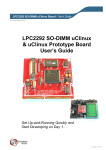
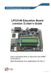
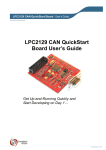
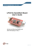
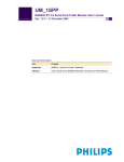
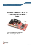
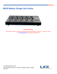
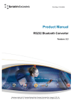
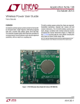
LPC2104 Color LCD Game Board - User’s Guide
Copyright 2006 © Embedded Artists AB
LPC2104 Color LCD Game
Board User’s Guide
Have some fun!
…and share your programs
EA2-USG-0605 v1.1 Rev A
LPC2104 Color LCD Game Board - User’s Guide
Page 2
Embedded Artists AB
Friisgatan 33
SE-214 21 Malmö
Sweden
[email protected]
http://www.EmbeddedArtists.com
Copyright 2005-2006 © Embedded Artists AB. All rights reserved.
No part of this publication may be reproduced, transmitted, transcribed, stored in a retrieval
system, or translated into any language or computer language, in any form or by any means,
electronic, mechanical, magnetic, optical, chemical, manual or otherwise, without the prior
written permission of Embedded Artists AB.
Disclaimer
Embedded Artists AB makes no representation or warranties with respect to the contents
hereof and specifically disclaim any implied warranties or merchantability or fitness for any
particular purpose. Information in this publication is subject to change without notice and
does not represent a commitment on the part of Embedded Artists AB.
Feedback
We appreciate any feedback you may have for improvements on this document. Please send
your comments to [email protected].
Trademarks
InfraBed and ESIC are trademarks of Embedded Artists AB. All other brand and product
names mentioned herein are trademarks, services marks, registered trademarks, or registered
service marks of their respective owners and should be treated as such.
Copyright 2006 © Embedded Artists AB
LPC2104 Color LCD Game Board - User’s Guide
Page 3
Table of Contents
1 Introduction
5
1.1
Contents
5
1.2
Features
5
1.3
Other Products from Embedded Artists
5
1.3.1
Design and Production Services
6
1.3.2
LPC2xxx QuickStart Boards and Kits
6
2 Getting Started
7
2.1
ESD Precaution
7
2.2
Up-and-Running Immediately
7
2.3
Different Board Versions
7
2.4
Jumpers
8
2.4.1
Board Version 1.0
8
2.4.2
Board Version 1.1
8
2.5
2.5.1
2.6
USB Driver
USB Driver Behavior
Pre-installed Applications
12
12
2.6.1
Startup sequence
12
2.6.2
Menu
12
2.6.3
Example Game
13
2.6.4
Snake
13
2.6.5
Pong
13
2.6.6
Bluetooth
14
2.6.7
Future Software Expansion
14
2.7
Bluetooth – BGB203-S06
14
2.8
Program Update
15
2.9
Battery Powered Operation
16
2.10
Troubleshooting
17
2.11
Don’t Do This…
18
3 Board Schematic
19
3.1
Board Schematics, version 1.1
19
3.2
Board Schematics, version 1.0
23
4 Program Development
4.1
Copyright 2006 © Embedded Artists AB
9
27
Program Development
27
4.1.1
IAR QuickStart Guide
27
4.1.2
GCC QuickStart Guide
27
4.1.3
Real-Time Operating System
28
4.1.4
Application Configuration
28
4.2
Converting Pictures to Bitmaps
28
4.3
Program Download via ISP (over USB)
29
4.4
Program Download via (embedded) JTAG
29
LPC2104 Color LCD Game Board - User’s Guide
Page 4
5 Product Registration
5.1
Product Registration
6 Further Information
Copyright 2006 © Embedded Artists AB
30
30
31
LPC2104 Color LCD Game Board - User’s Guide
Page 5
1 Introduction
Thank you for buying Embedded Artists’ LPC2104 Color LCD Game Board based on
Philips ARM7TDMI LPC2104 microcontroller.
1.1 Contents
The box received when ordering the LPC2104 Color LCD Game Board contains the
following:
•
The LPC2104 Color LCD Game Board, with or without embedded JTAG depending
on what board version ordered.
•
A USB cable of type: mini-B to A.
1.2 Features
Embedded Artists LPC2104 Color LCD Game Board with Philips ARM7TDMI LPC2104
microcontroller will give you some Summer Fun, but it also lets you get up-and-running
quickly with Philips LPC21xx series. The board has the following features:
•
Philips ARM7TDMI LPC2104 microcontroller with 128 KByte program Flash and
16 KByte SRAM
•
14.7456 MHz crystal for maximum execution speed and standard serial bit rates
−
Phase-locked loop (PLL) multiplies frequency with four; giving 58.9824 MHz
•
130 x 130 pixel color LCD with white LED backlight
•
Bluetooth communication based on Philips BGB203-S06. Implements the Serial
Port Profile (SPP).
•
Version exist with embedded JTAG, based on J-link™ technology
•
USB program download (ISP) via USB-to-UART bridge (FT232R chip)
•
Five key joystick for user input
•
2 LEDs
•
Piezo-electric buzzer.
•
On-board low-dropout voltage and reset generation
−
•
Powered via USB
Hand-held operation possible with 3x1.2V Ni-Mh batteries (not included).
−
"Trickle" charging of batteries supported via USB port
•
8 Kbit I2C E2PROM for storing non-volatile parameters
•
Small form factor: 90 x 90 mm
−
Four layer PCB (FR-4 material) for best noise immunity
It’s possible to download all software in source code for the board – to enhance, expand and
share!
1.3 Other Products from Embedded Artists
Embedded Artists have a broad range of LPC2xxx based boards that are very low cost and
developed for prototyping / development as well as for OEM applications. Modifications for
Copyright 2006 © Embedded Artists AB
LPC2104 Color LCD Game Board - User’s Guide
Page 6
OEM applications can be done easily, even for modest production volumes. Contact
Embedded Artists for further information about design and production services.
1.3.1
Design and Production Services
Embedded Artists provide design services for custom designs, either completely new or
modification to existing boards. Specific peripherals and I/O can be added easily to different
designs, for example, communication interfaces, specific analog or digital I/O, and power
supplies. Embedded Artists has a broad, and long, experience in designing industrial
electronics, in general, and with Philips LPC2xxx microcontroller family, in specific. Our
competence also includes wireless and wired communication for embedded systems. For
example IEEE802.11b/g (WLAN), Bluetooth™, ZigBee™, ISM RF, Ethernet, CAN, RS485,
and Fieldbuses.
1.3.2
LPC2xxx QuickStart Boards and Kits
Visit Embedded Artists’ home page, www.EmbeddedArtists.com, for information about
other QuickStart boards / kits or contact your local distributor.
Copyright 2006 © Embedded Artists AB
LPC2104 Color LCD Game Board - User’s Guide
Page 7
2 Getting Started
This chapter describes everything you need to know to use the LPC2104 Color LCD Game
Board. Please read this chapter before you starts to use the board.
2.1 ESD Precaution
Please note that the LPC2104 Color LCD Game Board comes without and case/box and all
components are exposed for finger touches.
Make it a habit to always first touch the metal surface of the USB connector with both hands
before you start using the board, e.g., playing. See picture to the right where to find the USB
connector.
USB connector
with grounded
metal case
Figure 1 – LPC2104 Color LCD Game Board Picture
2.2 Up-and-Running Immediately
Just connect the USB cable between a PC and the board. The LPC2104 Color LCD Game
Board will power up and you can immediately start playing the pre-installed games.
2.3 Different Board Versions
There exist two versions of the board; version 1.0 (which are the boards without embedded
JTAG) and version 1.1 (which are boards with embedded JTAG).
Version 1.1 of the board is designed to also allow the LPC2103 as main processor. Therefore
a number of components in the schematic are not mounted. Another main difference is that
version 1.1 uses an I2C port expander to have the needed I/O pins. When enabling JTAG on
the LPC2104, ETM is also automatically enabled. This “steels” a mayor part of the available
I/O pins of the chip, and hence the port expander is needed.
Version 1.0 and 1.1 are compatible in software since it is possible to sense which hardware
the software runs on (and adjust a few I/O specific functions accordingly).During startup the
application simply tests if I2C communication with the I2C port expander is possible. If so,
the application runs on v1.1 hardware. If not, it runs on v1.0 hardware.
Pictures of the board will show v1.1 in this document, since all relevant components /
jumpers are on the same place on the PCB. Any relevant differences will be noted.
Copyright 2006 © Embedded Artists AB
LPC2104 Color LCD Game Board - User’s Guide
Page 8
2.4 Jumpers
This section described the different jumpers on the board and how they control the operation.
2.4.1
Board Version 1.0
USB jumpers
Always insert upper two
jumpers to the right
USB-ISP jumpers
Should only be inserted when downloading new
program code via ISP. Not inserted under normal
operation.
USB Charge jumper
Should always be inserted,
unless “trickle” charging
batteries via USB
Crystal jumper
Should always be
in lower position
Figure 2 – Board Jumpers for v1.0
2.4.2
Board Version 1.1
The only difference in jumpers is that the
crystal jumper has been removed and enable
JTAG is actually mounted.
USB jumpers
Insert all three jumpers to the left to
enable embedded JTAG via USB. Move
to the right to disable JTAG and enable
USB Serial Port communication.
USB-ISP jumpers
Should only be inserted when
downloading new program code via
ISP. Should not be inserted when
working via JTAG
USB Charge jumper
Should always be inserted,
unless “trickle” charging
batteries via USB
JTAG Control jumpers
Should normally be
inserted. Remove when
battery operated.
Figure 3 - Board Jumpers for v1.1
Copyright 2006 © Embedded Artists AB
JTAG Enable jumper
Only inserted when
controlling the
LPC2104 via JTAG
LPC2104 Color LCD Game Board - User’s Guide
Page 9
2.5 USB Driver
A USB driver must be installed on your PC computer in order for the USB-to-UART chip
(FT232R) to function. Make sure to download the latest version of the driver, which can be
found at the following URL:
http://www.ftdichip.com/Drivers/VCP.htm (search for a FT232R driver for your operating
system).
Latest version of the driver (at the time of writing this document) is 2.00.00.
When the LPC2104 Color LCD Game Board is connected to the PC (via an USB cable) the
PC will ask for a driver. Unpack/unzip the downloaded driver file and brows to five the
position of the driver files.
After successful driver installation, a COM port will be created. Before communication with
the LPC2104 Color LCD Game Board can take place the UART settings must be correctly
set. The following description is valid for Windows™ XP, but other operating systems have
similar dialog windows. See the USB driver documentation for details, if needed.
To change UART settings, first open the System Properties dialog, as illustrated in Figure 4
below.
Device
Manager
Figure 4 – System Settings Dialog
Copyright 2006 © Embedded Artists AB
LPC2104 Color LCD Game Board - User’s Guide
Page 10
Then select the Device Manager and then open the Ports list, as illustrated in Figure 5
below.
Ports
Figure 5 – Device Manager Dialog
The new COM port (USB Serial Port) will be listed under the Ports list. Right-click on the
new USB Serial Port and select Properties, as illustrated in Figure 6 below.
USB Serial Port
Properties
Figure 6 – Device Manager Port Dialog
Copyright 2006 © Embedded Artists AB
LPC2104 Color LCD Game Board - User’s Guide
Page 11
Set 115200 bits per second, 8 data bits, none parity, 1 stop bit, and none flow control, as
illustrated in Figure 7 below. Then select Advanced settings.
UART settings
Advanced
settings
Figure 7 – USB Serial Port Properties Dialog
Set the desired COM port number under the Advanced settings dialog. Philips FLASH
Utility program (for ISP program download) needs, for example, a COM port number
between 1 and 5. Very often the COM port number selected but the USB Serial Port is
higher than this, so this needs to be changed manually.
It is common that all COM ports with low numbers are listed as occupied, but test to change
to a low number anyways. Very often it’s no problem at all to do this.
COM Port
Number Setting
Figure 8 – Advanced USB Serial Port Properties Dialog
Finally it’s time to test if you have successfully installed and configured the USB Serial Port.
Start a terminal program. Connect to the correct COM port, with 115200 bits per second,
8N1, no flow control. Remember to not have the USB-ISP jumpers inserted.
Copyright 2006 © Embedded Artists AB
LPC2104 Color LCD Game Board - User’s Guide
Page 12
A message like below should be printed on the terminal. Please not that the picture below is
just an example. The exact message will likely change for future program revisions.
Figure 9 – Example Terminal Window, Startup Message
Note that in case the USB interface is only used for powering the board, the driver is not
strictly needed. The two USB jumpers can then be removed in order to disconnect the
board’s data signals. If a program update is needed via ISP (the other alternative is via
embedded JTAG) the driver must be installed.
2.5.1
USB Driver Behavior
Sometimes the USB COM port does not enumerate properly when the board in connected to
the PC. This is a known “feature” of the USB driver. If you experience this problem, just
unplug the board shortly and then plug in again. A new COM port that can be accessed
properly should be created the second time.
This problem may occur after every time you start (i.e., power cycle) your PC.
If the ISP jumpers are inserted, pressing the reset button is often required in order to startup
the board (it can be placed in bootloader mode during startup due to RTS/DTR signal
handling by the USB driver during startup).
2.6 Pre-installed Applications
The LPC2104 Color LCD Game Board comes with software preinstalled. This section
describes the software functionality. Please note that this description applies for version 1.8
of the software. Later versions might change the behavior. Read the change notes when
updating the software versions for description of the (possible) changes.
2.6.1
Startup sequence
A startup sequence is displayed when the board is first powered up. It is possible to abort this
sequence by pressing any joystick key.
2.6.2
Menu
After the startup sequence, the main menu is displayed along with a small animated picture
sequence, just to illustrate the capabilities of the display and the system in general.
Use the joystick keys to move the cursor up and down. Select a menu position by pressing
the center key of the joystick.
Copyright 2006 © Embedded Artists AB
LPC2104 Color LCD Game Board - User’s Guide
Page 13
Please note that it’s possible to adjust the display contrast be pushing the left/right joystick
keys. The reset value may need change if temperature or light conditions change.
2.6.3
Example Game
This is the first example game implemented on the LPC2104 Color LCD Game Board. Move
the falling objects with the right/left joystick keys. Rotate the objects by pressing to up-key
and speed up the fall by pressing the down-key.
Score is shown at the bottom of the display. The drop speed increases with higher score.
When pressing the center key of the joystick a menu pops up where it’s possible to select
“Restart game” or “End game”. These are the same options as when the game is over
(overflowing the game board).
2.6.4
Snake
This is another well-known game. Start by pressing any joystick key. The snake will always
start to move in the right direction. Change direction with the joystick. “Eat” green dots and
avoid red (obstacle) dots. Whenever a greed dot is passed (= eaten) the length of the snake
increase with one. The snake is not allowed to cross the game board borders or its own body.
Level and score are shown at the bottom of the display. With increasing levels the number of
dots in the game board increases.
When pressing the center key of the joystick a menu pops up where it’s possible to select
“Restart game” or “End game”. These are the same options as when the game is over.
2.6.5
Pong
This game can be played either with one player or with two players. In the latter case,
Bluetooth us used for communication with the two players.
The first three choices presented to the payer are:
1. Single player game
In this case, move the paddles up and down with the joystick up/down keys. Select
active player (i.e., which paddle to move) with right/left joystick keys. If the center
key is held down when the ball hit a paddle, the ball speed will be increased.
2. Dual player game – act as client
In this case, the Bluetooth module will search for Pong servers (to play with). Select
the server to play with (from the presented list) and start to play. The server must
accept a connection request before the game can start.
When the game has started the paddle is moved up/down with the up/down joystick
keys. If the center key is held down when the ball hit a paddle, the ball speed will be
increased, else decrease.
If the communication channel is lost, the game is ended.
3. Dual player game – act as server
In this case, the Bluetooth module will act like a server, waiting for Pong game
clients to request connection (i.e., to start a game). The server will ask the user to
accept the connection request before the game is actually started.
When the game has started the paddle is moved up/down with the up/down joystick
keys. If the center key is held down when the ball hit a paddle, the ball speed will be
increased, else decrease.
If the communication channel is lost, the game is ended.
Please note that due to startup commands sent to the Bluetooth module, do not start the pong
game until 10 seconds after powerup. Else the Bluetooth communication might not function
properly.
Copyright 2006 © Embedded Artists AB
LPC2104 Color LCD Game Board - User’s Guide
2.6.6
Page 14
Bluetooth
This menu gives some direct interaction with the Bluetooth module, Philips BGB203-S06.
It’s possible to start a Bluetooth Inquiry and watch which other Bluetooth units are in the
proximity. It’s further possible to activate / disable the module and to control whether the
module is in command or data mode. It’s only when the module is in command mode that it
accepts AT commands. For further information about this, see section 2.7 below.
Please note that only active units in data mode can be discovered via an inquiry. Else they
will not show up in the list of found units (when other units perform an inquiry).
2.6.7
Future Software Expansion
Please note that there are many possibilities to enhance and expand the software for the
board. It’s possible to download all source code for the LPC2104 Color LCD Game Board.
All owners of this board are encouraged to continue working with the software and share it –
let all other users enjoy your enhancements!
Below are just a few ideas about enhancements:
•
Obviously more games
•
Create a general bitmap for cards (53 different, 4x13 + joker)
•
Dual player games over Bluetooth offers many interesting challenges
•
Dual play Pong game can be enhanced, for example moving ball in correct direction
even if communication is temporary disturbed.
•
Dual player pong where one player is a PC, for users with one board.
•
Handling of large scrollable menus. This if for example needed when more games
are added to the main menu and if many Bluetooth units are found during an inquiry.
•
Create a virtual machine (maybe a small JVM) so games can be downloaded over
Bluetooth
•
Add more graphical handling routines
•
Huffman encoding of pictures (in order to compress storage needed for pictures)
•
Handling of high-score (stored in on-board 8kbit EEPROM), maybe even implement
a registry handling to easily retrieve settings for different games
•
Make use of the on-board buzzer in the games
•
Make the code more general
Please keep the startup messages in the code, if possible.
2.7 Bluetooth – BGB203-S06
The Bluetooth module, i.e., Philips BGB203-S06, can be directly accessed via the USB
serial communication channel. Simply connect a terminal program to the COM port that the
USB driver creates. Make sure the USB serial channel settings are 115200 baud, 8N1, no
flow control. See section 2.5 above for details about how to change driver settings. Make
sure the jumpers for ISP program download is not inserted, since many terminal programs
control these signals in a way that will reset the LPC2104 Color LCD Game Board.
Read the BGB203-S06 User’s Manual for details about the module, including the available
commands. The document can be downloaded from the support page at Embedded Artists
after product registration. See details about product registration in chapter 5 below in this
document.
Copyright 2006 © Embedded Artists AB
LPC2104 Color LCD Game Board - User’s Guide
Page 15
A good command to start with is quickly send three plus signs (+++) in order to set the
module in AT command mode. An “OK” should be received in response to this command.
Then send “ATI” plus enter and a version response string will be received. This little test
ensures that the communication with the BGB203-S06 module has been established via the
terminal.
Please note that the Bluetooth module is not accessible via the USB-serial channel when a
game uses the Bluetooth module. In the current software version this applies to dual player
Pong game.
Please also note that it’s not a good idea to change the frequency calibration parameter. Each
LPC2104 Color LCD Game Board has been calibrated and changing this setting may alter
the frequency so that the Bluetooth module no longer can communicate with other units. A
recalibration is required in that case, which requires a very accurate frequency counter.
2.8 Program Update
This section describe how to perform a program update, i.e., how to download new software
in the module. The ISP functionality is used over the USB serial port that the FT232R chip
creates. For boards with embedded JTAG, see section 4.4 for details.
First of all, the jumpers must be properly inserted, as illustrated in picture below.
USB jumpers
Insert the two upper jumpers to the right
position to enable the USB serial port.
USB-ISP jumpers
Should be inserted.
USB Charge jumpers
Depends if battery
operated, or not.
JTAG Control jumpers
Should not be inserted.
JTAG Enable jumper
Should not be inserted.
Figure 10 – Jumper Setting for ISP Program Download
Secondly, make sure the created USB COM port is configured correctly, i.e., 115.2 kbps,
8N1, no flow control, and a COM port number between 1 and 5.
Third, start Philips Flash Utility program. Mare cure the Use DTR/RTS for Reset and
Bootloader Selection checkbox is selected, set correct crystal frequency (14756), correct
bitrate and COM port.
Copyright 2006 © Embedded Artists AB
LPC2104 Color LCD Game Board - User’s Guide
Page 16
Brows for hex file
Set COM port
Set bitrate
Check box
Figure 11 – Philips Flash Utility Program Window
Forth, test communication by pressing the Read Device ID button. The Part ID and Boot
Loader ID boxes should be updated with information is the program can communicate with
the LPC2104 on the board.
Finally, brows for the hex file to download and then press the Upload to Flash button. The
program download process takes about 60 seconds.
2.9 Battery Powered Operation
It is possible to power the LPC2104 Color LCD Game Board via rechargeable batteries.
Three (3) 1.2V Ni-Mh batteries are needed. Batteries are not included, nor is a battery
holder. The following steps are required to get the board battery operated.
1. Get a suitable battery holder. Fasten it, for example, on the backside on the board.
2. Solder the two wires from the battery holder to the board. See Figure 12 below for
details about where to solder.
3. On version 1.0 of the board, replace the two 0 ohm jumpers with four 180 ohm 0603
resistors. On version 1.1, the four 180 ohm resistors are already mounted.
See Figure 12 below for details where to find the resistors.
4. If the batteries are charged via the USB interface, remember to remove the USB
Charge Jumper in order to limit the charge current. This is important in order not to
damage the batteries or the USB interface of the PC. If batteries are not inserted/used
and USB power is used, the USB Charge Jumper must be inserted.
Note that the battery charging is very simple, i.e., trickle charging is implemented,
where the charge current is very low. Since the charge current is low, the batteries
can be left in charging mode all the time. The downside is long charging times, up to
8-14 hours. If faster charging time is needed, use an external battery charger.
5. Note that there is no reverse battery protection, so be careful when inserting
batteries.
Copyright 2006 © Embedded Artists AB
LPC2104 Color LCD Game Board - User’s Guide
Page 17
USB Charge Jumper
On v1.0,
replace these 0
ohm resistors
with two 180
ohm 0603
resistors.
On v1.0, solder
two 180 ohm
0603 resistors.
Attach wires
from battery
holder here.
Figure 12 – Battery Operated Board
2.10 Troubleshooting
Read this section if you experience any problem using your LPC2104 Color LCD Game
Board.
•
First of all, make sure you have all board jumpers in the correct positions. See
section 2.4 above for details.
•
The first time you plug in a board in the USB connector on your computer, a new
COM port may not be created properly. This is a known “feature” of the USB driver.
If you experience this problem, just unplug the board shortly and then plug in again.
A new COM port should be created the second time.
This problem may occur after every time you start (i.e., power cycle) your PC.
•
If the board does not start up properly after the USB cable is applied, first make sure
the ISP download jumpers are not inserted. Press reset to restart the board.
If this does not help, make sure the USB charge jumper is inserted. Press reset to
restart the board.
If this does not help, measure the voltages on the board to make sure the board gets
proper power via the USB cable. VUSB should be at least 4.5 volt. VCHRG should
be the same as VUSB as long as the USB charge jumper is inserted.
•
If the reset LED (lower left corner) lights constantly make sure the USB changer
jumper is inserted and make sure VUSB is at least 4.5 volt.
•
If your board does not find other Bluetooth units, check the following;
•
Copyright 2006 © Embedded Artists AB
o
Make sure all involved boards have different Bluetooth addresses. All
boards have different addresses when delivered but the address can easily be
changed.
o
Make sure the BGB203-S06 module is in data mode as opposed to
command mode). It’s only when in data mode the Bluetooth module can be
discovered.
If you have changed the crystal frequency calibration by accident and do not have
access to a precision frequency counter you can set the calibration parameter to the
LPC2104 Color LCD Game Board - User’s Guide
Page 18
mean value of all produced boards with a reasonable good result. Type the following
command to the BGB203-S06 Bluetooth module when in command mode:
AT+BTSET=2,100
2.11 Don’t Do This…
Do not try to remove the color display. It’s attached to the PCB by strong double sided
scotch. The display will definitively be damaged by any attempt to remove it from the PCB.
Do not recalibrate the BGB203-S06 module unless you have access to a precision frequency
counter.
Copyright 2006 © Embedded Artists AB
LPC2104 Color LCD Game Board - User’s Guide
Page 19
3 Board Schematic
This chapter contains schematics of the two different versions of the LPC2104 Color LCD
Game Board.
3.1 Board Schematics, version 1.1
Figure 13 - LPC2104 Color LCD Game Board with Bluetooth, version 1.1, page 1
Copyright 2006 © Embedded Artists AB
LPC2104 Color LCD Game Board - User’s Guide
Figure 14 - LPC2104 Color LCD Game Board with Bluetooth, version 1.1, page 2
Copyright 2006 © Embedded Artists AB
Page 20
LPC2104 Color LCD Game Board - User’s Guide
Figure 15 - LPC2104 Color LCD Game Board with Bluetooth, version 1.1, page 3
Copyright 2006 © Embedded Artists AB
Page 21
LPC2104 Color LCD Game Board - User’s Guide
Figure 16 - LPC2104 Color LCD Game Board with Bluetooth, version 1.1, page 4
Copyright 2006 © Embedded Artists AB
Page 22
LPC2104 Color LCD Game Board - User’s Guide
3.2 Board Schematics, version 1.0
Figure 17 - LPC2104 Color LCD Game Board with Bluetooth, version 1.0, page 1
Copyright 2006 © Embedded Artists AB
Page 23
LPC2104 Color LCD Game Board - User’s Guide
Figure 18 - LPC2104 Color LCD Game Board with Bluetooth, version 1.0, page 2
Copyright 2006 © Embedded Artists AB
Page 24
LPC2104 Color LCD Game Board - User’s Guide
Figure 19 - LPC2104 Color LCD Game Board with Bluetooth, version 1.0, page 3
Copyright 2006 © Embedded Artists AB
Page 25
LPC2104 Color LCD Game Board - User’s Guide
Figure 20 - LPC2104 Color LCD Game Board with Bluetooth, version 1.0, page 4
Copyright 2006 © Embedded Artists AB
Page 26
LPC2104 Color LCD Game Board - User’s Guide
Page 27
4 Program Development
All source code is available from the support page. You, as a user, are encouraged to
enhance the software and share with all other users of the LPC2104 Color LCD Game
Board. This chapter shortly describes how to get started, how to easily generate pictures for
the color LCD, and how to download new program code.
4.1 Program Development
The source code package is compatible with both IAR Embedded Workbench and GCC.
4.1.1
IAR QuickStart Guide
A project workspace file exists. Simply start IAR Embedded Workbench with this
workspace and all settings are correctly set.
4.1.2
GCC QuickStart Guide
Consult the QuickStart Program Development User’s Manual for more information about
the QuickStart Build Environment from Embedded Artists, and program development for the
ARM7 in general.
The source code is written for our QuickStart Build Environment, which is a very effective
and non-complicated program development environment. Below is a list of actions to
complete in order to get started with your program development.
•
Read the QuickStart Program Development User’s Manual and install GNUARM
and the QuickStart Build Environment from Embedded Artists.
Note that currently, only v3.4.3 of GCC is supported.
•
Make sure you have modified the bash files for your paths. In most cases this is done
by the install program.
•
Download the source code package from the support page. You must register as a
user before you get access to the support pages.
•
Unpack the zip-files to a suitable directory.
•
Open a QuickStart Build Environment prompt. Please note that this is not the same
as opening a DOS prompt, even though the windows looks similar. You will find the
QuickStart Build Environment under all installed programs: Embedded Artists
-> LPC2xxx-gcc-newlib -> LPC2xxx-gcc-newlib v2.3.0.0.
•
Change working directory in the QuickStart Build Environment prompt to the root of
the unpacked source code.
•
Compile and link by typing: make. It’s a good habit to always type: make clean
before the final build.
•
If you want to download the source code directly via ISP you can type: make
deploy. Before you do this make sure the correct COM port from the USB driver
is selected in the makefile. Simply open the makefile in an editor. At the end
of the file there is a row starting with: DL_COMPORT = com5. Change to the
correct COM port.
Please note that the download program does not work perfectly with the USB COM
driver. This problem can happen if the PC is loaded with many other tasks while
performing the download, for example playing streaming data. If a download error
occurs, either try again or switch to Philips Flash Utility download program. This
program works well with USB COM ports.
Copyright 2006 © Embedded Artists AB
LPC2104 Color LCD Game Board - User’s Guide
4.1.3
Page 28
Real-Time Operating System
A RTOS is included in the application in the form of a library. Five processes are supported
with priorities between 0 and 4. A process can have any priority and two, or more, processes
can have the same priority. Current revision of the source code (v1.9) use three processes.
Read the documentation under the pre_emptive_os\doc directory for details about the
RTOS.
4.1.4
Application Configuration
It is possible to configure some parts of the application via the include file
configAppl.h. Simply comment out the rows for the functionality to leave out when
compiling. It’s possible to reduce the code size below 32 kByte by commenting out all
configuration options.
4.2 Converting Pictures to Bitmaps
The 130x130 pixel color LCD can display pictures with high quality. The preinstalled
software use 8 bits color depth but the LCD controller also supports 12-bits color depth. For
8 bits, the RGB332 format is used, i.e., 3 bits are used for the red color, 3 bits for green and 2
bits for blue.
With the help of an image conversion program (written in JAVA) it’s possible to convert any
picture in the following formats; jpg, png, gif, bmp into a C-array that can easily be
downloaded into the display memory of the Color LCD. Prepare the picture if needed in any
picture manipulating program. Unusual picture formats can also be converted in any picture
manipulating program into any of the supported formats. Note that some formats of bmp are
not supported. The conversion program will signal this. If this happens, just convert into
another picture format.
The program can be instructed to cut smaller pictures than the 130x130 pixels of the display.
Figure 21 below illustrate the usage.
Figure 21 – JAVA Image Conversion Program
A typical command (from DOS prompt) can be:
java -jar img_conv.jar myPicture.jpg –f rgb332 –w 130 –h 130 –o myPic.h –c
The last –c option enables a simple compression scheme. There exist a simple unpacking
routine in the software platform. The compression algorithm simply aggregate bytes of the
same value into a short escape sequence.
Copyright 2006 © Embedded Artists AB
LPC2104 Color LCD Game Board - User’s Guide
Page 29
4.3 Program Download via ISP (over USB)
Please read section 2.8 for details about program download via ISP, over USB. Do not forget
to set the jumpers correct and to configure the USB COM port correctly (correct bitrate,
115.2 kbps and 8N1, no flow control).
4.4 Program Download via (embedded) JTAG
Use the IAR Embedded Workbench to download the completed via JTAG. The project is set
up to automatically download the code when debug mode is entered. According to postings
on the lpc2000 yahoo newsgroup there also exists a J-link GDB server for integration with
Insight/GDB. This has not been tested, but users are encouraged to share experiences.
Please note that what JTAG and USB Serial port share the same USB connector. When
JTAG is used, the USB serial port cannot be accessed.
Copyright 2006 © Embedded Artists AB
LPC2104 Color LCD Game Board - User’s Guide
Page 30
5 Product Registration
You can download a lot of valuable information and programs that will easy your program
development from the support pages. See details below about the product registration
process, which allows you to always have access to the latest versions.
5.1 Product Registration
By registering as a customer of Embedded Artists you will get access to valuable material
and information that will get you up-and-running instantly:
•
The latest version of the software, both as binary image (hex file) and as source
code.
•
Access to a Real-Time Operating System (RTOS), in the form of a library that can
be used for non-commercial applications. This library is part of the software.
•
Datasheets of all circuits on the LPC2104 Color LCD Game Board, including user’s
manual for the BGB203-S06 Bluetooth module.
•
QuickStart Build Environment from Embedded Artists, which contains a complete
setup of a build environment for GCC.
•
Image conversion program for generating bitmaps from pictures.
Registering is easy and done quickly.
1) Go to http://www.EmbeddedArtists.com, select Support and then Register.
2) Type in the products serial number (can be found on the ESD bag of the LPC2104
Color LCD Game Board) along with your personal information.
Copyright 2006 © Embedded Artists AB
LPC2104 Color LCD Game Board - User’s Guide
Page 31
6 Further Information
The LPC2104 microcontroller is a complex circuit and there exist a number of other
documents with a lot more information. The following documents are recommended as a
complement to this document.
[1] Philips LPC2104 Datasheet
http://www.semiconductors.philips.com/acrobat/datasheets/
LPC2104_2105_2106-05.pdf
[2] Philips LPC2104 User’s Manual
http://www.semiconductors.philips.com/acrobat/usermanuals/
UM_LPC2106_2105_2104_1.pdf
[3] Philips LPC2104 Errata Sheet
http://www.semiconductors.philips.com/acrobat/erratasheets/2104.pdf
[4] ARM7TDMI Technical Reference Manual. Document identity: DDI0029G
http://www.arm.com/pdfs/DDI0029G_7TDMI_R3_trm.pdf
[5] ARM Architecture Reference Manual. Document identity: DDI0100E
Book, Second Edition, edited by David Seal, Addison-Wesley: ISBN 0-201-73719-1
Also available in PDF form on the ARM Technical Publications CD
[6] ARM System Developer’s Guide – Designing and Optimizing System Software, by
A.N. Sloss, D Symes, C. Wright. Elsevier: ISBN 1-55860-874-5
[7] Embedded System Design on a Shoestring, by Lewin Edwards.
Newnes: ISBN 0750676094.
[8] GNU Manuals
http://www.gnu.org/manual/
[9] GNU ARM tool chain for Cygwin
http://www.gnuarm.com
[10] An Introduction to the GNU Compiler and Linker, by Bill Gatliff
http://www.billgatliff.com
[11] LPC2000 Yahoo Group. A discussion forum dedicated entirely to the Philips
LPC2xxx series of microcontrollers.
http://groups.yahoo.com/group/lpc2000/
[12] The Insider’s Guide to the Philips ARM7-Based Microcontrollers, by Trevor Martin.
http://www.hitex.co.uk/arm/lpc2000book/index.html
Especially note document [3]. There exist a number of bugs in the processor that is important
to be aware of.
Note that there can be newer versions of the documents than the ones linked to here. Always
check for the latest information / version.
Datasheets for all circuits can be downloaded from the support page.
Copyright 2006 © Embedded Artists AB