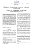
1
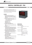
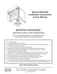
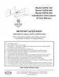
PUM Series
Multi-loop module type
Temperature controller
ENHANCED COMMUNICATION
MODULE (PROFIBUS) [PUMCP]
DATA SHEET
PUMCP
PUMCP is a communication module, which connects module
type temperature controller PUM series with PROFIBUS
system. Compatible with PROFIBUS DP-V0, and designed
for high-speed communication at the maximum speed of
12Mbps. Being able to up to 16 units (64 channel) of PUMA
(control module), PUMCP requires minimum wiring, less
space, and saves labor for engineering.
FEATURES
I. Program-less connection to PROFIBUS
1. PROFIBUS DP-V0 compatible
High-speed communication at max.12Mbps
2. Access to all parameters of control module (PUMA/
PUMB) via PROFIBUS
3. High-speed data communication with connected control
modules (PUMA/PUMB)
- Quick data importing and setting data reflection
II. User-friendly structure and functions
1. Lateral connection : Max.16 units (64 channels) + event
input/output module 16 units = total 32 units
Simple wiring for power supply and communication
2. Detachable structure: Terminal block, main unit, and
the base part
o Easy wiring with detachable terminal blcok
o Main units exchangeable without re-wiring
SYSTEM SPECIFICATION
1. Product type: Multi-loop module type temperature
controller
2. Module type
1) Analog module: Total maximum 16 units
a) Control module (4 loop/unit)
b) Extended input/output module
- Analog input/output module
(Input/output 4 points/unit)
- Analog input module (Input 4 points/unit)
- Analog output module (output 4 points/unit)
2) Extended input/output (digital) module:
Maximum 16 units
- Event input/output module
(Input/output ; 8 points/unit)
3) Enhanced communication module: 1 unit
3. Connecting method:
Lateral connecting with connectors
- For power supply and RS-485 communication,
any one of connected modules is required to be
connected.
4. No. of loop, input/output
1) Control loop:
Max. 64
2) No.of input / output: DI 128 points / DO 128 points
ENHANCED COMMUNICATION MODULE
(PROFIBUS) SPECIFICATION
1. General specification
(1) Power supply: 24V DC ±10%
(2) Power consumption: Max. 3.2 W (135 mA)
[when 24V DC is applied]
(3) Insulation resistance: 20M: or more (500V DC)
(4) Withstand voltage:
Power supply l loader communication
1000V AC 1 min.
Power supply l SLD/FG terminal, PROFIBUS communication 1000V AC 1 min.
(5) Applied standards:
UL, C-UL, CE Marking, RoHS directive
[Pending for UL and C-UL]
2. PROFIBUS communication module
2.1 PROFIBUS communication
(1) Compliant version: PROFIBUS DP-V0 (Cyclic communication)
(2) Station type: Slave device
(3) Communication speed and distance
Speed
9.6,19.2,
93.75
kbps
187.5
kbps
500 kbps
1.5Mbps
3M,6M,
12Mbps
Distance
1200m
or less
100m
or less
400m
or less
200m
or less
100m
or less
(4) Station number: Settable station number 1 to 99
(5) Communication data length (Cyclic communication)
Remote
input/output
bits
Remote
input/output
words
64 bits
8 words
128 bits
16 words
256 bits
32 words
512 bits
64 words
864 bits
108 words
(6) Connecting cable: Type A compatible cable for PROFIBUS
(7) Connecting method: M3 screw terminal block
(8) Termination resistace: External (220:, 1/2W) or depends
on the internal SW setting.
EDS11-172a
Date
Apr. 1, 2011
PUMCP
2.2 Display, configuration
(1) Display:
Status display LED
(2 colors × 2 points + 1 point)
(2) Display contents:
RUN/FAULT, control module connection
status (TX/RX), PROFIBUS status (ONL)
(3) Setting device and set contents
Setting device
Set contents
Front
Rotary SW × 2
PROFIBUS Station No. setting
Inside
Dip SW (3bits) × 1
Word setting of data exchange
(2) Ambient humidity:
90% RH or less (non condensing)
(3) Vibration:
10 to 70Hz, 9.8m/s2 (1G) or less
7. Transporting, storage condition (packing condition)
(1) Storage temperature: -20 to 60°C
(2) Ambient humidity: 90%RH or less (no condensing)
(3) Vibration:
10 to 70Hz, 9.8m/s2 (1G) or less
(4) Shock:
294m/s2 (30G) or less
8. Packing list
3. Power outage
(1) Impact of power outage:
Outage of 2ms or less ; no impact
(2) Operation after power outage:
Start from the first step (cold start)
(3) Memory backup:
Nonvolatile memory (EEPROM)
No. of update ; 100,000
4. Self diagnosis
Diagnosis method:
Program error monitoring by watch dog
timer
5. Structure
(1) Installation method:
DIN rail mounting or mounting with M3
screws inside a cabinet
(2) Dimensions: 30 (W) × 100 (H) × 85 (D) mm
(excluding terminal cover and projected
part)
(3) Weight:
Approx. 200 g
(4) Extrenal terminal
- PROFIBUS communication:
Detachable terminal block
(M3 screw × 20 terminals)
- Power supply connection:
Terminal block on the base part
(M3 screw × 2 terminals)
Power is supplied via side connectors
in case of lateral connecting. (Max. 33
units)
- Loader communication port:
2.5 diameter mini-plug / jack
[on the front of the module]
(5) Case material: Polyphenylene oxide
(flame retardant grade : UL94V-0 equivalent)
(6) Case color: Case ; red
Terminal, base part ; black
(7) Protection
- Body:
IP20 grade protection
(ventilation slits on the top and the bottom of the body)
- Terminal:
IP00 grade protection, terminal cover is
available as an option
Temperature controller: 1unit
Instruction manual:
1 copy
9. Loader software
(1) Distribution medium:
Free download from Fuji Electric Systems HP (http://www.fic-net.jp/eng/index.
html)
(2) Recommended operating environment
PC:
DOS/V (PC-AT compatible)
OS:
Windows XP (operation confirmed in
Japanese / English)
RAM:
256M bytes or more
Free space on the hardware: 500M bytes or more
Display resolution: 1024 × 768 dots or over
Serial interface: RS-232C 1 port
(without RS-232C, USB serial converter
cable required)
(3) Connection with PUM
Via loader interface on the front face of the module
(special cable available from Fuji is required)
CODE SYMBOLS
[Enhanced communication module]
Digit
1 2 3 4 5 6 7 8
9 10
P UM
0
Digit
Description
4 < Module type >
Enhanced communication module
5 < Communication function >
PROFIBUS communication
10 < Operation manual >
Japanese
English
YY1
C
P
A
B
Digit
[Accessories]
1 2 3 4 5 6 7 8
P UM Z *
Digit
Description
6 DIN rail mounting end plate
7 Side conneting terminal cover
(right & left 1 set)
8
Front face screw terminal cover
Loader connecting cable (RS-232C)
A 0 2
A 0 3
A 0 4
L 0 1
[Table 1] Insulation block diagram
Power
PROFIBUS communication
6. Normal operating condition
(1) Ambient temperature*: -10 to 50°C
* “Ambient temperature” is the temperature underneath the controller inside
the equpiment or the cabinet where
the controller is installed.
Loader communication port
Functional insulation (1000VAC)
Functional insulation (500VAC)
OUTLINE DIAGRAM (Unit : mm)
Front terminal cover (Option)
(10)
30
Base part
(Main unit is detached)
Terminal block
(at attach/detach)
85
Hole for screw mounting
STATION No. LOADER
×10
50
×1
6
100
1.5
DIN rail
6.1
Terminal screw
M3
5
Terminal
screw M3
(8)
(30)
Hole for screw
mounting
At mounting to the DIN rail
Locking tab
Main unit (at attach/detach)
Dimensions for screw mounting
Notice at the installation
Please keep the distance of 30mm from this instrument to radiate.
[50mm is recommended]
30 or more
88.5±0.2
(3)
(100)
30 or more
2-M3
(30)
9±0.2
30 +0.7
+0.2
PUMCP
TERMINAL CONNECTION DIAGRAM
Loader interface plug (RS-232C)
3 TX
2 RX
1 GND
I2.5 3-pole miniature plug
STATION No. LOADER
×10
×1
RTS
2P5
B(+)
A(−)
21
21
11
22
22
12
23
23
13
24
24
14
25
15
26
16
SLD
FG
Don’t
connect
12
13
25
26
2M
11
14
15
Don’t
connect
16
17
27
27
17
28
18
19
29
19
20
30
20
18
28
29
30
Base part
Power
3
2
4
1
2
+
1
-
DC24V
5
3
4
5
Don’t connect
PROFIBUS communication module status
Contents
Setting error
Readout/Write data setting range
Factory-set value
—
0101h: St. No. configuration SW (St. No.) is invalid
value
0102h: DIP SW (No. of words to exchange data) is
invalid value
0203h: St. No. stored in EEPROM is invalid value
0204h: No. of words to exchange data that is stored in
EEPROM is invalid value
0205h: Exchange pattern of Output data is invalid value
0206h: Exchange pattern of Input data is invalid value
0207h: Output area device size is invalid value
0208h: Input area device size is invalid value
0209h: Window communication pattern is invalid value
020Ah: Output area St. No. is invalid value
020Bh: Output area register No. is invalid value
020Ch: Input area St. No. is invalid value
020Dh: Input area register No. is invalid value
0211h: Window communication (EEPROM) is invalid
value
Register No.
30232
PUMCP
PROFIBUS communication setting
Contents
PROFIBUS communication
St. No.
PROFIBUS communication
setting for Output area
PROFIBUS communication
setting for Input area
Output area device size
Input area device size
Window communication
pattern
Readout/Write data setting range
1 to 125
Factory-set value
1
Register No.
40001
0 : 0 word
1 : 8 words
2 : 16 words
3 : 32 words
4 : 64 words
5 : 108 words
0 : 0 word
1 : 8 words
2 : 16 words
3 : 32 words
4 : 64 words
5 : 108 words
0 to 108 words
0 to 108 words
0: No Window communication
1: 1-word data communication
2: 2-word data communication
3: 4-word data communication
4: 8-word data communication
*The above is the max. No. of words
0
40003
0
40004
0
0
0
40104
40105
40106
Memory allocation (Output area)
0
41002
0: Not used
1 to 16: Control/Analog module
17 to 32: Event module
Note: Other than the above are not settable
0, 40000 to 49999 (Note1)
0
41003
0
41004
Output area entry
St. No. (108th word)
Output area entry
Register No. (108th word)
0: Not used
1 to 16: Control/Analog module
17 to 32: Event module
Note: Other than the above are not settable
0, 40000 to 49999 (Note1)
…
Register No.
41001
…
Output area entry
Register No. (2nd word)
Factory-set value
0
…
Output area entry
Register No. (1st word)
Output area entry
St. No. (2nd word)
Readout/Write data setting range
0: Not used
1 to 16: Control/Analog module
17 to 32: Event module
Note: Other than the above are not settable
0,40000 to 49999 (Note1)
…
Contents
Output area entry
St. No. (1st word)
0
41215
0
41216
Note1: Only the addresses written in “Output/Input area register No.” (User’s manual: PROFIBUS communication module INPTN5A0489-E) are settable. However, the parameters marked “*” in “Entry ban” column are not settable.
Memory allocation (Input area)
Input area entry
St. No. (108th word)
Input area entry
Register No. (108th word)
Register No.
43001
0
43002
0: Not used
1 to 16: Control/Analog module
17 to 32: Event module
Note: Other than the above are not settable
0, 30000 to 49999 (Note2)
0
43003
0
43004
0: Not used
1 to 16: Control/Analog module
17 to 32: Event module
Note: Other than the above are not settable
0, 30000 to 49999 (Note2)
…
…
Input area entry
Register No. (2nd word)
Factory-set value
0
…
Input area entry
Register No. (1st word)
Input area entry
St. No. (2nd word)
Readout/Write data setting range
0: Not used
1 to 16: Control/Analog module
17 to 32: Event module
Note: Other than the above are not settable
0, 30000 to 49999 (Note2)
…
Contents
Input area entry
St. No. (1st word)
0
43215
0
43216
Note2: Only the addresses written in “Output/Input area register No.” (User’s manual: PROFIBUS communication module INPTN5A0489-E) are settable. However, the parameters marked “*” in “Entry ban” column are not settable.
PUMCP
Fuji Electric
Your distributor:
Coulton Instrumentation Ltd
17 Somerford Business Park, Christchurch, BH23 3RU, UK
Tel: +44 1202 480 303
E-mail: [email protected]
Web: www.coulton.com
!