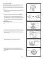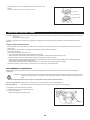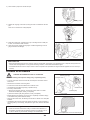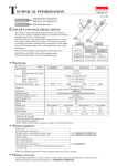
1
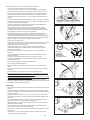
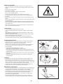
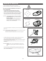
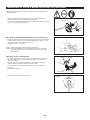
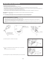
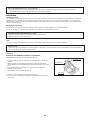
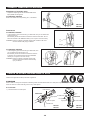
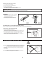
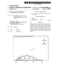
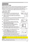
Petrol Brushcutter EBH252U EBH253U EBH252L EBH253L ORIGINAL INSTRUCTION MANUAL EBH252U EBH253U EBH252L EBH253L Important: Read this instruction manual carefully before putting the Petrol Brushcutter into operation and strictly observe the safety regulations! Preserve instruction manual carefully! English (Original instructions) Thank you very much for purchasing the MAKITA Petrol Brushcutter. We are pleased to recommend to you the MAKITA Petrol Brushcutter which is the result of a long development programme and many years of knowledge and experience. Please read this booklet which refers in detail to the various points that will demonstrate its outstanding performance. This will assist you to obtain the best possible result from your MAKITA Petrol Brushcutter. Table of Contents Page Symbols .........................................................................2 Safety instructions .........................................................3 Technical data................................................................7 Designation of parts.......................................................9 Mounting of handle ......................................................10 Mounting of protector................................................... 11 Mounting of cutter blade or nylon cutting head............12 Before start of operation ..............................................13 Correct handling of machine........................................15 Points in operation and how to stop ............................15 Resharpening the cutting tool ......................................17 Servicing instructions...................................................19 Storage ........................................................................22 SYMBOLS You will note the following symbols when reading the instructions manual. Read instruction manual and follow the warnings and safety precautions! Keep the area of operation clear of all persons and pets! Take Particular care and attention! Wear protective helmet, eye and ear protection! Forbidden! Top permissible tool speed Keep distance! Fuel (Gasoline) Flying object hazard! Engine-manual start No smoking! Emergency stop No open flame! First Aid Protective gloves must be worn! ON/START Wear sturdy boots with nonslip soles. Steeltoed safety boots are recommended! OFF/STOP Kickback! 2 SAFETY INSTRUCTIONS General Instructions – Read this instruction manual to become familiar with handling of the equipment. Users insufficiently informed will risk danger to themselves as well as others due to improper handling. – It is recommended only to lend the equipment to people who have proven to be experienced. Always hand over the instruction manual. – First users should ask the dealer for basic instructions to familiarize oneself with the handling of brushcutters. – Children and young persons aged under 18 years must not be allowed to operate this equipment. Persons over the age of 16 years may however use the device for the purpose of being trained while under supervision of a qualified trainer. – Use with the utmost care and attention. – Operate only if you are in good physical condition. Perform all work calmly and carefully. The user has to accept liability for others. – Never use this equipment after consumption of alcohol or drugs, or if feeling tired or ill. – National regulation can restrict the use of the machine. Intended use of the machine – This equipment is only intended for cutting grass, weeds, bushes, undergrowth. It should not be used for any other purpose such as edging or hedge cutting as this may cause injury. Personal protective equipment – The clothing worn should be functional and appropriate, i.e. it should be tightfitting but not cause hindrance. Do not wear either jewelry or clothing which could become entangled with bushes or shrubs. – In order to avoid either head-, eye-, hand-or foot injuries as well as to protect your hearing the following protective equipment and protective clothing must be used during operation. – Always wear a helmet where there is a risk of falling objects. The protective helmet (1) is to be checked at regular intervals for damage and is to be replaced at the latest after 5 years. Use only approved protective helmets. – The visor (2) of the helmet (or alternatively goggles) protects the face from flying debris and stones. During operation always wear goggles, or a visor to prevent eye injuries. – Wear adequate noise protection equipment to avoid hearing impairment (ear muffs (3), ear plugs etc.). – The work overalls (4) protect against flying stones and debris. We strongly recommend that the user wears work overalls. – Gloves (5) are part of the prescribed equipment and must always be worn during operation. – When using the equipment, always wear sturdy shoes (6) with a non-slip sole. This protects against injuries and ensures a good footing. Starting up the brushcutter – Please make sure that there are no children or other people within a working range of 15 meters (50 ft), also pay attention to any animals in the working vicinity. Diagrammatic figure – Before use always check the equipment is safe for operation: Check the security of the cutting tool, the throttle lever for easy action and check for proper functioning of the throttle lever lock. – Rotation of the cutting tool during idling speed is not allowed. Check with your dealer for adjustment if in doubt. Check for clean and dry handles and test the function of the start/stop switch. 3 15 Meters Start the brushcutter only in accordance with the instructions. – Do not use any other methods for starting the engine! – Use the brushcutter and the tools only for such applications as specified. – Only start the engine, after the entire assembly is done. Operation of the device is only permitted after all the appropriate accessories are attached! – Before starting make sure that the cutting tool has no contact with hard objects such as branches, stones etc. as the cutting tool will revolve when starting. – The engine is to be switched off immediately in case of any engine problems. – Should the cutting tool hit stones or other hard objects, immediately switch off the engine and inspect the cutting tool. – Inspect the cutting tool at short regular intervals for damage (detection of hairline cracks by means of tapping-noise test). – If the equipment gets heavy impact or fall, check the condition before continuing work. Check the fuel system for fuel leakage and the controls and safety devices for malfunction. If there is any damage or doubt, ask our authorized service center for the inspection and repair. – Operate the equipment only with the shoulder harness attached which is to be suitably adjusted before putting the brushcutter into operation. It is essential to adjust the shoulder harness according to the user size to prevent fatigue occurring during use. Never hold the cutter with one hand during use. – During operation always hold the brushcutter with both hands. Always ensure a safe footing. – Operate the equipment in such a manner as to avoid inhalation of the exhaust gases. Never run the engine in enclosed rooms (risk of gas poisoning). Carbon monoxide is an odorless gas. – Switch off the engine when resting and when leaving the equipment unattended, and place it in a safe location to prevent danger to others or damage to the machine. – Never put the hot brushcutter onto dry grass or onto any combustible materials. – Always install the approved cutting tool guard onto the equipment before starting the engine. Otherwise contact with the cutting tool may cause serious injury. • Resting • Transport • Refuelling • Maintenance • Tool replacement – All protective installations and guards supplied with the machine must be used during operation. – Never operate the engine with faulty exhaust muffler. – Shut off the engine during transport. – When transporting the equipment, always attach the cover to the cutting blade. – Ensure safe position of the equipment during car transportation to avoid fuel leakage. – When transporting, ensure that the fuel tank is completely empty. – When unloading the equipment from the truck, never drop the Engine to the ground or this may severely damage the fuel tank. – Except in case of emergency, never drop or cast the equipment to the ground or this may severely damage the equipment. – Remember to lift the entire equipment from the ground when moving the equipment. Dragging the fuel tank is highly dangerous and will cause damage and leakage of fuel, possibly causing fire. Refueling – Shut off the engine during refueling, keep away from open flames and do not smoke. – Avoid skin contact with mineral oil products. Do not inhale fuel vapor. Always wear protective gloves during refueling. Change and clean protective clothing at regular intervals. – Take care not to spill either fuel or oil in order to prevent soil contamination (environmental protection). Clean the brushcutter immediately after fuel has been spilt. – Avoid any fuel contact with your clothing. Change your clothing instantly if fuel has been spilt on it (to prevent clothing catching fire). – Inspect the fuel cap at regular intervals making sure that it can be securely fastened and does not leak. – Carefully tighten the fuel tank cap. Change location to start the engine (at least 3 meters away from the place of refueling). – Never refuel in closed rooms. Fuel vapors accumulate at ground lever (risk of explosions). – Only transport and store fuel in approved containers. Make sure the fuel stored is not accessible to children. 4 ter e 3m s Method of operation – Only use in good light and visibility. During the winter season beware of slippery or wet areas, ice and snow (risk of slipping). Always ensure a safe footing. – Never cut above waist height. – Never stand on a ladder. – Never climb up into trees to perform cutting operation. – Never work on unstable surfaces. – Remove sand, stones, nails etc. found within the working range. Foreign particles may damage the cutting tool and can cause dangerous kick-backs. – Before commencing cutting, the cutting tool must have reached full working speed. – When using metal blades, swing the tool evenly in half-circle from right to left, like using a scythe. If grass or branches get caught between the cutting tool and guard, always stop the engine before cleaning. Otherwise unintentional blade rotation may cause serious injury. – Take a rest to prevent loss of control caused by fatigue. We recommend to take a 10 to 20-minute rest every hour. Cutting Tools – Use an applicable cutting tool for the job in hand. Nylon cutting heads (string trimmer heads) are suitable for trimming lawn grass. Metal blades are suitable for cutting weeds, high grasses, bushes, shrubs, underwood, thicket, and the like. Never use other blades including metal multi-piece pivoting chains and flail blades. Otherwise serious injury may result. – When using metal blades, avoid “kickback” and always prepare for an accidental kickback. See the section “Kickback” and “Kickback prevention.” Kickback (blade thrust) – Kickback (blade thrust) is a sudden reaction to a caught or bound cutting blade. Once it occurs, the equipment is thrown sideway or toward the operator at great force and it may cause serious injury. Caution: Kickback – Kickback occurs particularly when applying the blade segment between 12 and 2 o’clock to solids, bushes and trees with 3 cm or larger diameter. – To avoid kickback: • Apply the segment between 8 and 11 o’clock; • Never apply the segment between 12 and 2 o’clock; • Never apply the segment between 11 and 12 o’clock and between 2 and 5 o’clock, unless the operator is well trained and experienced and does it at his/her own risk; • Never use cutting blades close to solids, such as fences, walls, tree trunks and stones; • Never use cutting blades vertically, for such operations as edging and trimming hedges. Diagrammatic figure Vibration – People with poor circulation who are exposed to excessive vibration may experience injury to blood vessels or the nervous system. Vibration may cause the following symptoms to occur in the fingers, hands or wrists: “Falling asleep” (numbness), tingling, pain, stabbing sensation, alteration of skin color or of the skin. If any of these symptoms occur, see a physician! – To reduce the risk of “white finger disease”, keep your hands warm during operation and well maintain the equipment and accessories. Maintenance instructions – Have your equipment serviced by our authorized service center, always using only genuine replacement parts. Incorrect repair and poor maintenance can shorten the life of the equipment and increase the risk of accidents. – The condition of the cutter, in particular of the cutting tool of the protective devices and also of the shoulder harness must be checked before commencing work. Particular attention is to be paid to the cutting blades which must be correctly sharpened. – Turn off the engine and remove spark plug connector when replacing or sharpening cutting tools, and also when cleaning the cutter or cutting tool. 5 Diagrammatic figure Never straighten or weld damaged cutting tools. – Pay attention to the environment. Avoid unnecessary throttle operation for less pollution and noise emissions. Adjust the carburetor correctly. – Clean the equipment at regular intervals and check that all screws and nuts are well tightened. – Never service or store the equipment in the vicinity of naked flames. – Always store the equipment in locked rooms and with an emptied fuel tank. – When cleaning, servicing and storing the equipment, always attach the cover to the cutting blade. Observe the relevant accident prevention instructions issued by the relevant trade associations and by the insurance companies. Do not perform any modifications to the equipment as this will endanger your safety. The performance of maintenance or repair work by the user is limited to those activities as described in the instruction manual. All other work is to be done by an Authorized Service Agent. Use only genuine spare parts and accessories released and supplied by MAKITA. Use of non-approved accessories and tools means increased risk of accidents. MAKITA will not accept any liability for accidents or damage caused by the use of non-approved cutting tools and fixing devices of cutting tools, or accessories. First Aid In case of accident make sure that a first-aid box is available in the vicinity of the cutting operations. Immediately replace any item taken from the first aid box. When asking for help, please give the following information: – Place of accident – What happened – Number of injured persons – Kind of injuries – Your name For European countries only EC Declaration of Conformity We Makita Corporation as the responsible manufacturer declare that the following Makita machine(s): Designation of Machine: Petrol Brushcutter Model No./ Type: EBH252U, EBH253U, EBH252L, EBH253L Specifications: see “TECHNICAL DATA” table are of series production and Conforms to the following European Directives: 2000/14/EC, 2006/42/EC And are manufactured in accordance with the following standards or standardized documents: EN ISO 11806-1 The technical documentation is kept by: Makita International Europe Ltd., Technical Department, Michigan Drive, Tongwell, Milton Keynes, Bucks MK15 8JD, England The conformity assessment procedure required by Directive 2000/14/EC was in Accordance with annex V. Measured Sound Power Level: 109.3 dB Guaranteed Sound Power Level: 111 dB 19. 12. 2008 Tomoyasu Kato Director Makita Corporation 3-11-8, Sumiyoshi-cho, Anjo, Aichi, JAPAN 6 TECHNICAL DATA EBH252U, EBH252L Model Dimensions: length x width x height (without cutting blade) Mass (without plastic guard and cutting blade) mm kg EBH252U EBH252L Bike handle Loop handle 1,770 x 620 x 490 1,770 x 330 x 275 5.7 5.3 Volume (fuel tank) L 0.5 Volume (oil tank) L 0.08 3 24.5 Engine displacement cm Maximum engine performance 0.71 at 7,000 min-1 kw Engine speed at recommended max. spindle speed min-1 8,500 Maximum spindle speed (corresponding) min-1 6,500 Maximum fuel consumption kg/h 0.33 g/kwh 408 Maximum specific fuel consumption -1 3,000 Idling speed min Carburetor type WALBRO WYL Ignition system type Solid state ignition Spark plug type NGK CMR4A Electrode gap mm 0.7 - 0.8 Vibration per ISO 22867 Right handle (Rear grip) Left handle (Front grip) Sound pressure level average to ISO 22868 Sound power level average to ISO 22868 ahv eq Uncertainty K ahv eq m/s2 2.5 5.0 2 0.58 1.23 2 2.9 4.3 2 0.37 0.36 m/s m/s Uncertainty K m/s LPA eq dBA 97.1 Uncertainty K dBA 2.4 LWA eq dBA 106.3 Uncertainty K dBA 1.2 Fuel Automobile gasoline SAE 10W-30 oil of API Ciassification, Class SF or higher (4-stroke engine for automobile) Engine Oil Cutting tools (cutter blade dia.) mm 230 Gear ratio 14/19 7 TECHNICAL DATA EBH253U, EBH253L Model Dimensions: length x width x height (without cutting blade) Mass (without plastic guard and cutting blade) mm kg EBH253U EBH253L Bike handle Loop handle 1,770 x 620 x 490 1,770 x 330 x 275 5.9 5.4 Volume (fuel tank) L 0.5 Volume (oil tank) L 0.08 3 24.5 Engine displacement cm Maximum engine performance 0.71 at 7,000 min-1 kw Engine speed at recommended max. spindle speed min-1 8,500 Maximum spindle speed (corresponding) min-1 6,500 Maximum fuel consumption kg/h 0.33 g/kwh 408 Maximum specific fuel consumption -1 3,000 Idling speed min Carburetor type WALBRO WYL Ignition system type Solid state ignition Spark plug type NGK CMR4A Electrode gap mm 0.7 - 0.8 Vibration per ISO 22867 Right handle (Rear grip) Left handle (Front grip) Sound pressure level average to ISO 22868 Sound power level average to ISO 22868 ahv eq Uncertainty K ahv eq m/s2 2.6 5.3 2 0.83 1.22 2 2.3 4.4 2 0.52 0.21 m/s m/s Uncertainty K m/s LPA eq dBA 97.1 Uncertainty K dBA 2.4 LWA eq dBA 106.3 Uncertainty K dBA 1.2 Fuel Automobile gasoline SAE 10W-30 oil of API Ciassification, Class SF or higher (4-stroke engine for automobile) Engine Oil Cutting tools (cutter blade dia.) mm 230 Gear ratio 14/19 8 DESIGNATION OF PARTS EBH252U EBH253U EBH252L EBH253L ⑤ ⑤ ⑫ ④ ⑦ ④ ⑨ ⑦ ⑧ ⑨ ⑫ ⑩ ⑪ ⑪ ⑩ ⑬ ⑯ ⑬ ⑮ ⑮ ⑭ ⑭ ⑰ ⑱ GB ⑥ ③ ⑳ 21 22 ⑲ ① ② 9 DESIGNATION OF PARTS 1 Fuel tank 2 Rewind starter 3 Air cleaner 4 I-O switch (on/off) 5 Spark plug 6 Exhaust muffler 7 Clutch case 8 Rear grip 9 Hanger 10 Handle 11 Control lever 12 Control cable 13 Shaft 14 Protector (Cutting tool guard) 15 Gear Case/Head case 16 Handle holder 17 Cutter blade 18 Nylon cutting head 19 Fuel filler cap 20 Starter knob 21 Exhaust pipe 22 Oil gauge MOUNTING OF HANDLE CAUTION: Before doing any work on the Petrol Brushcutter, always stop the engine and pull the spark plug connector off the spark plug. Always wear protective gloves! CAUTION: Start the Petrol Brushcutter only after having assembled it completely. For machines with bike handle models – Loosen knob (1). (1) – Place handle (4) between handle clamp (2) and handle holder (3). (2) – Adjust handle (4) to an angle that provides a comfortable working position and then secure by firmly hand-tightening knob (1). (4) CAUTION: Do not forget to mount spring (5). (3) (5) Engine For machines with loop handle – Fix a barrier to the left side of the machine together with the handle for operator protection. – Make sure that the grip/barrier assembly is fitted between the spacer and the arrow mark. WARNING: Do not remove or shrink the spacer. The spacer keeps a certain distance between both hands. Setting the grip/barrier assembly close to the other grip beyond the length of the spacer may cause loss of control and serious personal injury. 10 Engine Arrow mark MOUNTING OF PROTECTOR To meet the applicable safety provisions, only the tool/ protector combinations as indicated in the table must be used. Be sure to use genuine MAKITA cutter blades or nylon cutting head. Protector for metal blades Metal blade – The cutter blade must be well polished, free of cracks or breakage. If the cutter blade hits against a stone during operation, stop the engine and check the blade immediately. – Polish or replace the cutter blade every three hours of operation. – If the nylon cutting head hits against a stone during operation, stop the engine and check the nylon cutting head immediately. CAUTION: The appropriate protector must always be installed, for your own safety and in order to comply with accidentprevention regulations. Operation of the equipment without the guard being in place is not permitted. The outside diameter of the cutter blade must be 230 mm (9-1/16”). Never use any blades surpassing 230 mm (9-1/16”) in outside diameter. Protector for nylon cutting head Nylon cutting head – In use of the metal blade, fix the protector (3) to the clamp (2) with two bolts M6 x 30 (1). NOTE: Tighten the right and left bolts evenly so that the gap between the clamp (2) and the protector (3) will be constant. Otherwise, the protector sometimes may not function as specified. (1) (3) (2) – In cases where the nylon cord cutter is to be used, be sure to mount the nylon cord cutter protector (4) onto the metal blade protector (3). – Mount the nylon cord cutter protector (4) by sliding it into place from the flank of the metal blade protector (3) as shown. (3) – Remove tape adhered to cutter, which cuts nylon cord, on nylon cord cutter protector (4). CAUTION: Be sure to push in nylon cord cutter protector (4) until it is fully inserted. Take care not to injure yourself on the cutter for cutting the nylon cord. (4) – To remove the nylon cord cutter protector (4), apply a hex wrench into the notch on the metal blade protector (3), push it in and meanwhile slide the nylon cord cutter protector (4). Hex wrench 11 MOUNTING OF CUTTER BLADE OR NYLON CUTTING HEAD Turn the machine upside down, and you can replace the cutter blade or nylon cutting head easily. – Insert the hex wrench through the hole in the gear case and rotate the receiver washer (4) until it is locked with the hex wrench. (4) Hex wrench – Loosen the nut (1) (left-hand thread) with the socket wrench and remove the nut (1), cup (2), and clamp washer (3). (3) (2) (1) Mounting of cutterblade with the hex wrench still in place – Mount the cutter blade onto the shaft so that the guide of the receiver washer (4) fits in the arbor hole in the cutter blade. Install the clamp washer (3), cup (2), and secure the cutter blade with the nut (1). [Tightening torque: 13 - 23 N-m] NOTE: Always wear gloves when handling the cutter blade. NOTE: The cutter blade-fastening nut (with spring washer) is a consumable part. If there appears any wear or deformation on the spring washer, replace the nut. Hex wrench Mounting of nylon cutting head Loosen – The clamp washer (3), cup (2), and nut (1) are not necessary for mounting the nylon cutting head. The nylon cutting head should go on top of the receiver washer (4). – Insert the hex wrench through the hole in the gear case and rotate the receiver washer (4) until it is locked with the hex wrench. (4) – Then screw the nylon cutting head onto the shaft by turning it counterclockwise. – Remove the hex wrench. Hex wrench – Make sure that the blade is the left way up. Rotation 12 Tighten BEFORE START OF OPERATION Inspection and refill of engine oil – Perform the following procedure, with the engine cooled down. – While keeping the engine level, remove the oil gauge, and confirm that the oil is filled within the upper and lower limit marks. When the oil is in short in such a way that the oil gauge touches the oil only by its tip, in particular with the oil gauge remaining inserted in the crankcase without screwing-in (Fig. 1), refill new oil near the port (Fig. 2). – For reference, the oil refill time is about 10h (10 times or 10 tanks of oil refill). If the oil changes in color or mixes with dirt, replace it with new one. (For the interval and method of replacement, refer to P 19) Recommended oil: SAE 10W-30 oil of API Classification, Class SF or higher (4-stroke engine for automobile) Oil volume: Approx. 0.08L Note: If the engine is not kept upright, oil may go into around the engine, and may be refilled excessively. If the oil is filled above the limit, the oil may be contaminated or may catch fire with white smoke. Point 1 in Replacement of oil: “Oil gauge” – Remove dust or dirt near the oil refill port, and detach the oil gauge. – Keep the detached oil gauge free of sand or dust. Otherwise, any sand or dust adhering to the oil gauge may cause irregular oil circulation or wear on the engine parts, which will result in troubles. – As an example to keep the oil gauge clean, it is recommended to insert the oil gauge on its knob side into the engine cover, as shown in Fig. 3. Upper limit (Edge of oil refill port) Oil gauge If oil adheres around this tip, refill new oil. Fig. 1 Fig. 2 Fig. 3 (1) Keep the engine level, and detach the oil gauge. (2) Fill oil up to the edge of the oil refill port. (Refer to Fig. 2 of the preceding page). Feed oil with the lubricant refill container. (3) Securely tighten the oil gauge. Insufficient tightening may cause oil leakage. 13 Point 2 in Replacement of oil: “If oil spills out” – If oil spills out between the fuel tank and engine main unit, the oil is sucked into through the cooling air intake port, which will contaminate the engine. Be sure to wipe out spilt oil before start of operation. REFUELING Handling of fuel It is necessary to handle fuel with utmost care. Fuel may contain substances similar to solvents. Refueling must be performed in a sufficiently ventilated room or in the open air. Never inhale fuel vapor, and keep fuel away from you. If you touch fuel repeatedly or for a long time, the skin becomes dry, which may cause skin disease or allergy. If fuel enters into the eye, clean the eye with fresh water. If your eye remains still irritated, consult your doctor. Storage period of fuel Fuel should be used up within a period of 4 weeks, even if it is kept in a special container in a well-ventilated shade. If a special container is not used or if the container is not covered, fuel may deteriorate in one day. STORAGE OF MACHINE AND REFILL TANK – Keep the machine and tank at a cool place free from direct sunshine. – Never keep the fuel in the cabin or trunk. Fuel The engine is a four-stroke engine. Be sure to use an automobile gasoline (regular gasoline or premium gasoline). Points for fuel – Never use a gasoline mixture which contains engine oil. Otherwise, it will cause excessive carbon accumulation or mechanical troubles. – Use of deteriorated oil will cause irregular startup. Refueling WARNING: INFLAMMABLES STRICTLY PROHIBITED Gasoline used: Automobile gasoline (unleaded gasoline) – Loosen the tank cap a little so that there will be no difference in atmospheric pressure. – Detach the tank cap, and refuel, discharging air by tilting the fuel tank so that the refuel port will be oriented upward. (Never refill fuel full to the oil refill port.) Fuel tank cap Fuel upper limit – Wipe well the periphery of the tank cap to prevent foreign matter from entering into the fuel tank. – After refueling, securely tighten the tank cap. Fuel tank ● If there is any flaw or damage on the tank cap, replace it. ● The tank cap is consumable, and therefore should be renewed every two to three years. 14 CORRECT HANDLING OF MACHINE Attachment of shoulder strap – Adjust the strap length so that the cutter blade will be kept parallel with the ground. Buckle For EBH252U, EBH253U NOTE: Be careful not to trap clothing, etc., in the buckle. EBH252U EBH253U Detachment For EBH252L, EBH253L – In an emergency, push the notches (1) at both sides, and you can detach the machine from you. Be extremely careful to maintain control of the machine at this time. Do not allow the machine to be deflected toward you or anyone in the work vicinity. (1) WARNING: Failure to maintain complete control of the machine at all could result in serious bodily injury or DEATH. Hanger For EBH252U, EBH253U – In an emergency, push the notches (2) at both sides, and you can detach the machine from you. Be extremely careful to maintain control of the machine at this time. Do not allow the machine to be deflected toward you or anyone in the work vicinity. WARNING: Failure to maintain complete control of the machine at all could result in serious bodily injury or DEATH. (2) POINTS IN OPERATION AND HOW TO STOP Observe the applicable accident prevention regulations! STARTING Move at least 3 m away from the place of refuelling. Place the Petrol Brushcutter on a clean piece of ground taking care that the cutting tool does not come into contact with the ground or any other objects. A: Cold start 1) Set this machine on a flat space. Lock-off lever OPERATION STOP STOP High speed Throttle lever (1) OPERATION Low speed Low speed High speed Lock-off lever Throttle lever (1) 15 EBH252L EBH253L EBH252U EBH253U 2) Set the I-O switch (1) to OPERATION. CLOSE 3) Choke lever Close the choke lever. Choke opening: – Full closing in cold or when the engine is cold. – Full or half opening in restart just after stop of operation. 4) Primer pump Continue to push the primer pump until fuel enters into the primer pump. (In general, fuel enters into the primer pump by 7 to 10 pushes.) If the primer pump is pushed excessively, an excess of gasoline returns to the fuel tank. Carburetor Primer Pump 5) Recoil starter Pull the start knob gently until it is hard to pull (compression point). Then, return the start knob, and pull it strongly. Never pull the rope to the full. Once the start knob is pulled, never release your hand immediately. Hold the start knob until it returns to its original point. 6) Choke lever When the engine starts, open the choke lever. – Open the choke lever progressively while checking the engine operation. Be sure to open the choke lever to the full in the end. – In cold or when the engine is cooled down, never open the choke lever suddenly. Otherwise, the engine may stop. OPEN 7) Warm-up operation Continue warm-up operation for 2 to 3 minutes. Note: – If the starter handle is pulled repeatedly when the choke lever remains at “CLOSE” position, the engine will not start easily due to excessive fuel intake. – In case of excessive fuel intake, remove the spark plug and pull the starter handle slowly to remove excess fuel. Also, dry the electrode section of the spark plug. Caution during operation: If the throttle lever is opened fully in a no-load operation, the engine rotation is increased to 10,000 min-1 or more. Never operate the engine at a higher speed than required and at an approximate speed of 6,000 - 8,500 min-1. 16 B: Startup after warm-up operation 1) Push the primer pump repeatedly. 2) Keep the throttle lever at the idling position. 3) Pull the recoil starter strongly. 4) If it is difficult to start the engine, open the throttle by about 1/3. Pay attention to the cutter blade which may rotate. Attention in Operation When the engine is operated upside down, white smoke may come out from the muffler. STOPPING 1) Release the throttle lever (2) fully, and when the engine rpm has lowered, set the I-O switch to STOP the engine will now stop. STOP (2) 2) Be aware that the cutting head may not stop immediately and allow it to slow down fully. (1) STOP (2) (1) EBH252L EBH253L ADJUSTMENT OF LOW-SPEED ROTATION (IDLING) When it is necessary to adjust the low-speed rotation (idling), perform it by the carburetor adjusting screw. CHECKUP OF LOW-SPEED ROTATION Adjusting screw – Set the low-speed rotation to 3,000 min-1. If it is necessary to change the rotation speed, regulate the adjusting screw (illustrated on the right), with Phillips screwdriver. – Turn the adjusting screw to the right, and the engine rotation will increase. Turn the adjusting screw to the left, and the engine rotation will drop. – The carburetor is generally adjusted before shipment. If it is necessary to readjust it, please contact Authorized Service Agent. RESHARPENING THE CUTTING TOOL CAUTION: The cutting tools mentioned below must only be resharpened by an authorized facility. Manual resharpening will result in imbalances of the cutting tool causing vibrations and damage to the equipment. – cutter blade An expert resharpening and balancing service is provided by Authorized Service Agents. NOTE: To increase the service life of the cutter blade it may be turned over once, until both cutting edges have become blunt. 17 Carburetor EBH252U EBH253U NYLON CUTTING HEAD Most effective cutting area The nylon cutting head is a dual string trimmer head capable of both automatic and bump & feed mechanisms. The nylon cutting head will automatically feed out the proper length of nylon cord by the changes in centrifugal force caused by increasing or decreasing rpms. However, to cut soft grass more efficiently, bump the nylon cutting head against the ground to feed out extra cord as indicated under operation section. Operation – Increase the nylon cutting head speed to approx. 6,000 min-1. Low speed (under 4,800 min-1) is not suitable, the nylon cord will not feed out properly at low speed. – The most effective cutting area is shown by the shaded area. Idle speed Full speed If the nylon cord does not feed out automatically proceed as follows: 1. Release the throttle lever to run the engine idle and then squeeze the throttle lever fully. Repeat this procedure until the nylon cord feeds out to the proper length. 2. If the nylon cord is too short to feed out automatically with the above procedure, bump the knob of the nylon cutting head against the ground to feed out the nylon cord. 3. If the nylon cord does not feed out with procedure 2, rewind/replace the nylon cord by following the procedures described under “Replacing the nylon cord.” Knob Replacing the nylon cord – First, stop the engine. – Press on the housing latches inward to lift off the cover, then remove the spool. Cover Latches Press – Hook the center of new nylon cord into the notch in the center of the spool, with one end of the cord extending about 80 mm (3-1/8”) more than the other. Then wind both ends firmly around the spool in the direction of the head rotation (left-hand direction indicated by LH and right-hand direction by RH on the side of the spool). Press Spool 80 mm (3-1/8”) For left hand rotation Spool – Wind all but about 100 mm (3-15/16”) of the cords, leaving the ends temporarily hooked through a notch on the side of the spool. 100 mm (3-15/16”) Notches – Mount the spool in the housing so that the grooves and protrusions on the spool match up with those in the housing. Keep the side with letters on the spool visible on the top. Now, unhook the ends of the cord from their temporary position and feed the cords through the eyelets to come out of the housing. 18 Eyelets – Align the protrusion on the underside of the cover with the slots of the eyelets. Then push cover firmly onto the housing to secure it. Cover Protrusion Slot of eyelet SERVICING INSTRUCTIONS CAUTION: Before doing any work on the Petrol Brushcutter, always stop the engine and pull the plug cap off the spark plug (see “checking the spark plug”). Always wear protective gloves! To ensure a long service life and to avoid any damage to the equipment, the following servicing operations should be performed at regular intervals. Daily checkup and maintenance – Before operation, check the machine for loose screws or missing parts. Pay particular attention to the tightness of the cutter blade or nylon cutting head. – Before operation, always check for clogging of the cooling air passage and the cylinder fins. Clean them if necessary. – Perform the following work daily after use: • Clean the Petrol Brushcutter externally and inspect for damage. • Clean the air filter. When working under extremely dusty conditions, clean the filter the severall times a day. • Check the blade or the nylon cutting head for damage and make sure it is firmly mounted. • Check that there is sufficient difference between idling and engagement speed to ensure that the cutting tool is at a standstill while the engine is idling (if necessary reduce idling speed). If under idling conditions the tool should still continue to run, consult your nearest Authorized Service Agent. – Check the functioning of the I-O switch, the lock-off lever, the control lever, and the look button. REPLACEMENT OF ENGINE OIL Deteriorated engine oil will shorten the life of the sliding and rotating parts to a great extent. Be sure to check the period and quantity of replacement. ATTENTION: In general, the engine main unit and engine oil still remain hot just after the engine is stopped. In replacement of oil, confirm that the engine main unit and engine oil are sufficiently cooled down. Otherwise, there may remain a risk of scald. Note: If the oil filled above the limit, it may be contaminated or may catch fire with white smoke. Interval of replacement: Initially, every 20 operating hours, and subsequently every 50 operating hours Recommended oil: SAE10W-30 oil of API Classification SF Class or higher (4-stroke engine oil for automobile) In replacement, perform the following procedure. 1) Confirm that the tank cap is tightened securely. Fuel tank cap 2) Detach the oil gauge. Keep the oil gauge free from dust or dirt. Oil gauge 19 3) Place waste or paper near the oil refill port. Waste or paper 4) Detach the oil gauge, and drain oil, tilting the main unit toward the oil refill port. Drain oil in a container for orderly disposal. 5) Keep the engine level, and feed new oil up to the edge of the oil refill port. In refill, use a lubricant refill container. 6) After refill, securely tighten the oil gauge. Insufficient tightening of the oil gauge will lead to oil leakage. POINTS ON OIL – Never discard replaced engine oil in garbage, earth or sewage ditch. Disposal of oil is regulated by law. In disposal, always follow the relevant laws and regulations. For any points remaining unknown, contact Authorized Service Agent. – Oil will deteriorate even when it is kept unused. Perform inspection and replacement at regular intervals (replace with new oil every 6 months). CLEANING OF AIR CLEANER DANGER: INFLAMMABLES STRICTLY PROHIBITED Element (sponge) Interval of Cleaning and Inspection: Daily (every 10 operating hours) Plate Air cleaner cover – Turn the choke lever to the full close side, and keep the carburetor off from dust or dirt. – Remove the air cleaner cover-fixing bolts. – Pull the cover lower side and detach the air cleaner cover. – If oil adheres to the element (sponge), squeeze it firmly. Breather Part – For heavy contamination: 1) Remove the element (sponge), immerse it in warm water or in waterdiluted neutral detergent, and dry it completely. 2) Clean the element (felt) with gasoline, and dry it completely. Element (felt) Fixing bolt – Before attaching the element, be sure to dry it completely. Insufficient drying of the element may lead to difficult startup. – Wipe out with waste cloth, oil adhering around the air cleaner cover and plate breather. – Immediately after cleaning is finished, attach the cleaner cover and tighten it with fixing bolts. (In remounting, first place the upper claw, and then the lower claw.) Points in Handling Air Cleaner Element – Clean the element several times a day, if excessive dust adheres to it. – If operation continues with the element remaining not cleared of oil, oil in the air cleaner may fall outside, resulting in oil contamination. 20 Pick this part and remove the element (felt). CHECKING THE SPARK PLUG – Only use the supplied universal wrench to remove or to install the spark plug. – The gap between the two electrodes of the spark plug should be 0.7 - 0.8 mm (0.028” - 0.032”). If the gap is too wide or too narrow, adjust it. If the spark plug is clogged or contaminated, clean it thoroughly or replace it. CAUTION: Never touch the spark plug connector while the engine is running (danger of high voltage electric shock). 0.7 mm - 0.8 mm (0.028” - 0.032”) SUPPLY OF GREASE TO GEAR CASE – Supply grease (Shell Alvania 2 or equivalent) to the gear case through the grease hole every 30 hours. (Genuine MAKITA grease may be purchased from your MAKITA dealer.) Gear case Grease hole CLEANING OF FUEL FILTER WARNING: INFLAMMABLES STRICTLY PROHIBITED Interval of Cleaning and Inspection: Monthly (every 50 operating hours) Fuel pipe House clamp Suction head in the fuel tank – The fuel filter (1) of the suction head is used to filter the fuel required by the carburetor. – A periodical visual inspection of the fuel filter is to be conducted. For that purpose open the tank cap, use a wire hook and pull out the suction head through the tank opening. Filters found to have hardened, been polluted or clogged up are to be replaced. Fuel filter (1) – Insufficient fuel supply can result in the admissible maximum speed being exceeded. It is therefore important to replace the fuel filter at least quarterly to ensure satisfactory fuel supply to the carburetor. REPLACEMENT OF FUEL PIPE CAUTION: INFLAMMABLES STRICTLY PROHIBITED Fuel pipe Interval of Cleaning and Inspection: Daily (every 10 operating hours) Replacement: Annually (every 200 operating hours) Replace the fuel pipe every year, regardless of operating frequency. Fuel leakage may lead to fire. If any leakage is detected during inspection, replace the oil pipe immediately. INSPECTION OF BOLTS, NUTS AND SCREWS – Retighten loose bolts, nuts, etc. – Check for fuel and oil leakage. – Replace damaged parts with new ones for safety operation. CLEANING OF PARTS – Keep the engine always clean. – Keep the cylinder fins free of dust or dirt. Dust or dirt adhering to the fins will cause piston seizure. REPLACEMENT OF GASKETS AND PACKINGS In reassembling after the engine is dismounted, be sure to replace the gaskets and packings with new ones. Any maintenance of adjustment work that is not included and described in this manual is only to be performed by Authorized Service Agents. 21 STORAGE WARNING: When draining the fuel, be sure to stop the engine and confirm that the engine cools down. Just after stopping the engine, it may still hot with possibility of burns, inflammability and fire. ATTENTION: When the machine is kept out of operation for a long time, drain up all fuel from the fuel tank and carburetor, and keep it at a dry and clean place. – Drain up fuel from the fuel tank and carburetor according to the following procedure: 1) Remove the fuel tank cap, and drain fuel completely. If there is any foreign matter remaining in the fuel tank, remove it completely. 2) Pull out the fuel filter from the refill port using a wire. 3) Push the primer pump until fuel is drained from there, and drain fuel coming into the fuel tank. 4) Reset the filter to the fuel tank, and securely tighten the fuel tank cap. 5) Then, continue to operate the engine until it stops. Drain fuel Humidity – Remove the spark plug, and drip several drops of engine oil through the spark plug hole. – Gently pull the starter handle so that engine oil will spread over the engine, and attach the spark plug. – Attach the cover to the cutter blade. – During storage, keep the rod horizontal or keep the machine upright with the blade edge oriented upward. (In this case, pay full attention to prevent the machine from falling.) Never store the machine with the cutter blade edge oriented downward. Lubricating oil may spill out. – Keep the drained fuel in a special container in a well-ventilated shade. Attention after long-time storage – Before startup after long-time shutdown, be sure to replace oil (refer to P 19). Oil will deteriorate while the machine is kept out of operation. Fault location Fault System Observation Cause Engine not starting or with difficulty Ignition system Ignition spark O.K. Fault in fuel supply or compression system, mechanical defect No ignition spark STOP-switch operated, wiring fault or short circuit, spark plug or connector defective, ignition module faulty Fuel supply Fuel tank filled Incorrect choke position, carburetor defective, fuel supply line bent or blocked, fuel dirty Compression No compression when pulled over Cylinder bottom gasket defective, crankshaft seals damaged, cylinder or piston rings defective or improper sealing of spark plug Mechanical fault Starter not engaging Broken starter spring, broken parts inside of the engine Tank filled ignition spark existing Carburetor contaminated, have it cleaned Tank filled Incorrect idling adjustment, carburetor contaminated Warm start problems Engine starts but dies Fuel supply Fuel tank vent defective, fuel supply line interrupted, cable or STOP-switch faulty Insufficient performance Several systems may simultaneously be affected Engine idling poor 22 Air filter contaminated, carburetor contaminated, muffler clogged, exhaust duct in the cylinder clogged Operating time Before After operation lubrication Item Daily (10h) 30h 50h 200h Shutdown/ Corresrest ponding P Inspect/clean 13 Engine oil Replace Tightening parts (bolt, nut) *1 19 Inspect 21 Clean/inspect — Fuel tank Drain fuel *3 22 Throttle lever Check function — Stop switch Check function 17 Cutting blade Inspect 11 Low-speed rotation Inspect/adjust 17 Air cleaner Clean 20 Ignition plug Inspect 21 Cooling air duct Clean/inspect 21 Inspect 21 Fuel pipe Replace *2 — Gear-case grease Refill 21 Fuel filter Clean/replace 21 Clearance between air intake Adjust valve and air discharge valve *2 — Engine overhaul *2 — Carburetor Drain fuel *3 *1 Perform initial replacement after 20h operation. *2 For the 200 operating hour inspection, request Authorized Service Agent or a machine shop. *3 After emptying the fuel tank, continue to run the engine and drain fuel in the carburetor. 23 22 TROUBLESHOOTING Before making a request for repairs, check a trouble for yourself. If any abnormality is found, control your machine according to the description of this manual. Never tamper or dismount any part contrary to the description. For repairs, contact Authorized Service Agent or local dealership. State of abnormality Probable cause (malfunction) Failure to operate primer pump Push 7 to 10 times Low pulling speed of starter rope Pull strongly Lack of fuel Feed fuel Clogged fuel filter Clean Broken fuel tube Straighten fuel tube Deteriorated fuel Deteriorated fuel makes starting more difficult. Replace with new one. (Recommended replacement: 1 month) Excessive suction of fuel Set throttle lever from medium speed to high speed, and pull starter handle until engine starts. Once engine starts, cutter blade starts rotating. Pay full attention to cutter blade. If engine will not start still, remove spark plug, make electrode dry, and reassemble them as they originally are. Then, start as specified. Detached plug cap Attach securely Contaminated spark plug Clean Abnormal clearance of spark plug Adjust clearance Other abnormality of spark plug Replace Abnormal carburetor Make request for inspection and maintenance. Starter rope cannot be pulled Make request for inspection and maintenance. Abnormal drive system Make request for inspection and maintenance. Insufficient warm-up Perform warm-up operation Choke lever is set to “CLOSE” although engine is warmed up. Set to “OPEN” Clogged fuel filter Clean Contaminated or clogged air cleaner Clean Abnormal carburetor Make request for inspection and maintenance. Abnormal drive system Make request for inspection and maintenance. Loosened cutter blade-tightening nut Tighten securely Twigs caught by cutter blade or dispersionpreventing cover. Remove foreign matter Abnormal drive system Make request for inspection and maintenance. Broken, bent or worn cutter blade Replace cutter blade Loosened cutter blade-tightening nut Tighten securely Shifted convex part of cutter blade and cutter blade support fitting. Attach securely Abnormal drive system Make request for inspection and maintenance. High idling rotation Adjust Detached throttle wire Attach securely Abnormal drive system Make request for inspection and maintenance. Detached connector Attach securely Abnormal electric system Make request for inspection and maintenance. Engine does not start Engine stops soon Engine speed does not increase Cutter blade does not rotate Stop engine immediately Main unit vibrates abnormally Stop engine immediately Cutter blade does not stop immediately Stop engine immediately Engine does not stop Remedy Run engine at idling, and set choke lever to CLOSE When the engine does not start after warm-up operation: If there is no abnormality found for the check items, open the throttle by about 1/3 and start the engine. 24 25 26 27 Makita Corporation Anjo, Aichi, Japan 884909F228 ALA www.makita.com