1
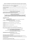
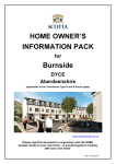
User Instruction manual
for Cardale Autoglide
NOTE TO INSTALLER: This user manual is supplied for the
instruction of the end user. It contains important safety and
warranty information. This manual MUST be left with the end
user on completion of the installation and after carrying out
setting and safety checks.
Thank you for buying a Cardale Autoglide electric
operator. This product will give many years of useful
service provided it is used correctly and is properly
maintained.
IMPORTANT SAFETY INSTRUCTIONS
WARNING – IT IS VITAL FOR THE SAFETY OF PERSONS
TO FOLLOW ALL INSTRUCTIONS
PLEASE KEEP THESE INSTRUCTIONS
The opener should be activated only when the door is in
full view, free of obstacles and correctly adjusted. Nobody should
enter or leave the garage while the door is moving. Children should
NOT be allowed to play near the door.
Never let children operate, or play with the door controls.
Keep remote control away from children
SAFETY NOTE: If there is a chance that children may play in
the entry of the garage then ensure the child lock is ENABLED
so that the door CANNOT be operated from the
button
(see Section 6c)
Always keep a moving door in sight and away from people and
objects until it is completely closed.
NO ONE SHOULD CROSS THE PATH OF A MOVING DOOR.
The safety reverse system test is very important.
Your garage door must reverse when obstructed on closing.
Failure to properly adjust the operator may
result in serious personal injury from a closing garage door.
Repeat the test once a month and make any needed
adjustments (see Section 5 in this manual – Safety Sensitivity
check.)
Do not use the force adjustments to compensate for a binding or sticking garage
door. Excessive force will interfere with the proper operation of the safety reverse
system or damage the garage door.
Keep garage door balanced. Sticking or binding doors must be repaired. Garage
doors, door springs, cables, pulleys, brackets, and their hardware are under
extreme tension and can cause serious personal injury. Do not attempt
adjustment. Call for professional garage door service.
Installation and wiring must be in compliance with your local building and
electrical codes. Connect the power cord only to properly earthed mains. Use the
ring main 13 amp 3 pin socket installed by a qualified electrician. The plug should
be fitted with a 5 amp fuse.
THIS APPLIANCE MUST BE EARTHED.
NOTE: For optimum electrical safety this operator should be connected to a
circuit protected by an R.C.D (Max 30mA trip rating).
If the garage has no service entrance door then an exterior release kit MUST
be fitted. This accessory allows manual operation of the garage door from outside
in case of power failure (See page 19).
Disconnect electric power to the garage door operator before making repairs
or removing cover.
Use the manual release lever to disengage the motor drive ONLY when the
drive is switched OFF and, if possible, when the door is fully closed.
Frequently examine the installation, in particular the cables, spring and
mountings, for signs of wear, damage or imbalance. Do not use if repair or
adjustment is needed since a fault in the installation or an incorrectly balanced door
may cause injury. Call for professional garage door service.
IMPORTANT SAFETY NOTE
Only operate the door when the door is in full view, free of obstacles with no
persons (particularly children) near the door. Nobody should be allowed to enter or
leave the garage whilst the door is in motion.
2
1 How to operate your Autoglide door opener
1
Stand by mode
When the Autoglide unit is switched on and in STAND BY MODE awaiting a
command the following indicator LED will be seen on the control cover.
LED – Constant red indicating “power on”.
LED – will be flashing green or constant green dependant on CHILD LOCK
setting (see Section 6c).
IN LEARN MODE
See relevant section for description.
IN STANDBY MODE (awaiting command)
Continuous GREEN – child lock enabled
ORANGE when
Continuous
remote control
RED power
signal is
on to unit.
received.
Flash GREEN – child lock disabled
IN RUN MODE
Continuous GREEN – motor running, door
in motion
Flash RED – obstruction or other problem
LED.
BUTTONS
up/down – Press this button to
handset –
config – Configures the
open/close the door (depending
Configures the
power /sensitivity
on child lock config). In set-up
remote control
settings of the motor
mode this button selects the
handset(s).
and configures the child
enable /disable of the child lock.
lock.
•
Figure A
3
2
To open/close from outside the garage.
– Use the remote control handset.
– Press the selected button for approximately 1 second.
– A red LED on the hand transmitter indicates that the signal is
being sent.
– An orange LED will light above the
button to indicate signal
has been received.
3
To open/close from inside the garage.
– Use the handset as in item 2.
– Alternatively use the
button on the front of the unit,
provided the child lock is disabled (flashing green
LED
(see Section 6c)).
– Or, use the remote bell push button.
NOTE: Whenever the unit is operated the courtesy lamp is illuminated.
This stays on for approximately 3 minutes and goes off automatically.
IMPORTANT SAFETY NOTE
Only operate the door when the door is in full view, free of obstacles with no
persons (particularly children) near the door. Nobody should be allowed to enter
or leave the garage whilst the door is in motion.
4
If the handset or stop button is operated whilst the door is
still in motion.
– The door will stop and remain in that position until the next
command signal is received.
– The next operation of the handset or button will reverse
the direction of travel of the door.
5
If the door is obstructed whilst closing.
– The safety sensitivity circuit will activate and stop the door.
The door will then reverse to the fully open position.
6
If the door is obstructed whilst opening.
– The safety sensitivity circuit will activate and stop the door.
– The door will stay in this position until it receives another
command signal, it will then go to fully closed position.
NOTE: Because the Autoglide utilises the existing latching arrangement on your
door you MUST keep the door locked
at all times.
4
2 How to use the manual release
1
The manual release lever disengages the motor drive from the door, and
allows the door to be opened and closed manually.
2
It can be used in an emergency (power cuts etc) or when carrying out checks
and adjustments to door operation in manual mode.
3
CAUTION! Only use the manual release lever when the POWER to the unit
has been turned OFF and for safety only disengage lever when door is closed,
if possible.
4
The manual release lever is situated on the drive unit (see Figure B) and is
coloured red.
5
To disengage the power drive, push the lever in the direction indicated in
Figure B.
To re-engage the drive pin:
1
Ensure power switch on the unit is in the OFF position.
2
Identify drive pin hole in Dymetrol tape in drive track (hole is marked with
silver paint). See Figure C.
10 mm
diameter
hole
•
Figure B
•
Figure C
5
3
Position the garage door so that the red manual release lever aligns with the
10mm diameter hole.
4
Pull the manual release lever back so that drive pin fully engages into the hole
(see Figure D).
5
Check pin is correctly engaged by trying to manually open/close door, the
door should not be able to move. If it does then repeat steps 2–4.
6
Switch power on and test operation of door.
NOTE: In the event of power failure the MANUAL RELEASE LEVER can be used
to restore door to normal manual operation.
When using the door in manual mode you should lock/unlock the door with the
key to maintain security.
IMPORTANT NOTE
If your garage has no service door then an exterior release kit MUST be fitted. This
accessory allows manual operation of the garage door from outside in case of an
emergency.
•
6
Figure D
3 In the event of power cuts
1
If the garage door remains unused during the power cut, you have to do
nothing. The control unit will automatically reset itself when the power comes
back on.
2
If you have to use the garage door then the manual release lever can be
utilised to give manual operation. See Section 2 for details.
3
Turn off mains power to the control unit when in manual mode.
4
Re-engage motor drive when mains power is restored. See Section 2 for
details.
IMPORTANT NOTE
When using the door in manual mode you should lock/unlock the door with the key
to maintain security.
4 Remote control
1
Operation of handset
– Press the button for approx 1 second, the red LED on the
handset indicates the signal is being sent.
– The handset is not directional and does not have to be pointed
at any sensors.
– It should work perfectly from within an enclosed car, you do not
have to wind down the windows.
2
Handset battery
– The handset is powered by a 12v alkaline battery type GP27A.
– If the LED, on the handset begins to ’flash‘ when the transmit
button is depressed, this indicates a LOW BATTERY condition and
the battery must be changed.
(see overleaf for availability)
7
3
Changing battery
– Using a small Philips screwdriver carefully
remove and retain the two screws from
the rear of the handset (see Figure E).
– Prise apart the two halves of the handset
and remove the old battery.
– Replace with new battery ensuring that it
is the correct way round
– Re-assemble cover and tighten screws.
DISPOSE OF THE OLD BATTERY SAFELY AS PER
MANUFACTURERS RECOMMENDATIONS
NOTE: New batteries (type GP27A can be obtained
from:–
•
Figure E
Cardale spares department telephone:
Direct phone/fax (01280) 840471
Main switchboard (01280) 703022
Quote part No. AZSP 7030
Farnell Ltd telephone: 01132 636311
Quote part No. 724-051
CPC Ltd telephone: 01772 654455
Quote part No. BTGP 27A–4
5 Safety sensitivity check
The safety reverse system should be tested once a month to ensure correct
operation and to maintain safety.
Your Autoglide control system contains advanced electronics that monitor the
power over the full OPEN/CLOSE cycle and computes a SENSITIVITY FACTOR to
ensure user safety.
To check the operation of this, signal the door to close and when it is halfway
down obstruct the door at the bottom edge using both hands.
Using only light to medium force the door should stop and then reverse to the
fully open position.
If excessively heavy force (or extremely light force) is required to stop the door
then RE-CONFIGURE the POWER and SENSITIVITY SET UP as instructed in
Section 6a.
8
6 Configuring your Autoglide operator
Autoglide can be quickly and easily set-up by the use of three buttons, each of
which has a corresponding status LED.
IN LEARN MODE
See relevant section for description.
IN STANDBY MODE (awaiting command)
Continuous GREEN – child lock enabled
ORANGE when
Flash GREEN – child lock disabled
Continuous
remote control
IN RUN MODE
RED power
signal is
Continuous GREEN – motor running,
on to unit.
received.
door in motion
Flash RED – obstruction or other problem
LED
BUTTONS
up/down – Press this button to
handset –
config – Configures the
open/close the door (depending
Configures the
power /sensitivity
on child lock config). In set-up
remote control
settings of the motor
mode this button selects the
handset(s).
and configures the child
enable /disable of the child lock.
•
Figure F
lock.
9
6a Configuring the power and sensitivity
set up
Ensure that the power switch on the unit is in the OFF
ON/OFF
switch
position (see Figure G).
NOTE: Before commencing power set up sequence ensure
that:–
Power input
socket and
fuse
Lamp out
connector
a Limit switches are correctly set
b All latches operate correctly
c Drive pin is correctly engaged
Bell push
connector
d Door is clear of obstructions
Check the power supply cable is plugged in
(see Figure G) and mains is turned on, leave the
•
switch on the unit turned OFF for the moment.
Figure G
1
Press and hold down the
button.
Turn on the unit power switch then release the button.
2
The RED LED above the button
should flash briefly to show door is
between the limit switches.
Briefly press the
button once to move the door to the fully
open position.
NOTE: If the motor runs but the door does not move and the
LED flashes
red, TURN OFF POWER. Ensure drive pin is correctly engaged in drive tape (see
Section 2) Then restart set up sequence.
3
With the door now fully open, briefly press the
button once to close the
door for the DOWN LEARN sequence.
4
When the door is closed briefly press the
button again to open the door
for the UP LEARN sequence.
5
The
LED should now show green or flashing green to confirm that set-up
has been successfully completed.
NOTE: Where necessary, move the limit switches up or down (no more than 6mm
at a time) to ensure the door fully opens and closes without excessive slamming. Go
through stages 1–4 each time a limit switch is adjusted.
10
6b Configuring the remote control handset
Ensure that the power switch on the unit is in the OFF position
(see Figure G)
Check the power supply cable is plugged in (see Figure G) and mains is turned on,
but leave the switch on the unit turned off for the moment.
1
Press and hold down the
2
The
3
Release the
4
Press and hold down the
5
The
6
Keeping the
button and turn on the unit power switch.
LED should light red.
button.
button again.
LED should light orange.
button held down, press either button on
the handset. The orange LED should flash.
7
Release the HANDSET button.
8
Wait for the orange LED to stop flashing and light constant orange
9
Now press the HANDSET button again. The orange LED should now
go out.
10 Release the
button
NOTE: To set up another handset repeat stages 4–10. When you have finished
setting up the handsets(s) continue with stage 11.
11 Configuration of handset buttons – with the
button released, press the
handset button that you wish to use to operate the door.
The
LED should light orange to acknowledge receipt of the signal.
In addition, if the left button is pressed the
right button is pressed the
LED will flash red, if the
LED will flash green.
If you want to change buttons, press both buttons on the handset
simultaneously to reset (the
LED will flash orange) and repeat
this stage.
Repeat this stage to configure additional handsets.
12 Press the
13 The
button to store your settings.
LED should show green/flashing green, indicating that the handset(s)
have been successfully configured.
11
NOTES:
A
Up to a maximum of 8 handsets can be memorised into the
control unit.
B
If you wish to ERASE handset codes:–
– Follow previous instructions to step 3 inclusive.
– Press
button FIVE TIMES (orange LED will stay on after
the fifth press).
– Press
button to accept this instruction.
– The
LED will now show GREEN/FLASHING GREEN indicating
that you have returned to normal STANDBY MODE.
– This will have erased ALL stored handset codes, if there are
any that you wish to retain you must re-enter them by
following previous steps 1-13.
C
Courtesy lamp (if fitted).
– In standby mode it is possible to turn on the courtesy lamp
(without operating the door) by simply pressing both buttons
on the handset simultaneously.
– The lamp will stay on for approximately 3 minutes before
automatically turning itself off.
6c Configuring the child lock
Ensure that the power switch on the unit is in the off position
(see Figure G).
Check the power supply cable is plugged in (see Figure G) and mains is turned on,
but leave the switch on the unit turned off for the moment.
1
Press and hold down the
2
The
3
Release the
4
The
5
If RED, the lock is DISABLED i.e. door can be opened using the
button. Turn on the unit power switch.
LED should briefly flash green.
button.
LED will now be red or green.
button.
6
If GREEN, then lock is ENABLED i.e. door cannot be opened using
the
12
7
button.
To change the status of the lock press the
button and the
change to either red or green as the button is depressed.
LED will
8
To save the child lock settings press and release the
9
If the lock is disabled the
10 If the lock is enabled the
button.
LED will flash green (can open door).
LED will shine constant green (cannot open
door).
NOTE: Whether the child lock is enabled or disabled, Autoglide can still be
operated using the handset.
SAFETY NOTE: If there is a chance that children may play in the entry of the garage
then ensure the child lock is ENABLED so that the door CANNOT be operated
from the
button
7 Adjusting top & bottom limits
Turn power switch on unit to OFF whilst making
adjustments
NOTE: Do not strain the limit switch cables.
Temporarily withdraw the cables from the drive track
grooves (if necessary) and refit correctly after adjusting
limit switches.
Move up to
reduce slam
action
Use a small Philips screwdriver to undo retaining
screw prior to adjusting limit switch and re-tighten
when adjustment is completed.
1
Bottom
limit
switch
Adjusting bottom limit switch (see Figure H)
Move down
to increase
slam action
– If door fails to close them move switch
downwards.
– If door slams too heavily or slams and
opens again immediately then move
switch upwards.
•
Figure H
13
2
Adjusting top, limit switch (see Figure J)
– If door fails to open far enough then
move switch upwards
– If door is opening too far and hitting
track stops or straining lifting gear then
move switch downwards.
NOTE: Only move the limit switch 1–2mm at
Increased
open HT
a time and test door operation by switching power
back on and opening/closing door.
Top
limit
switch
IMPORTANT: Reconfigure the power and Sensitivity
Decreased
open HT
settings after adjusting the limit switches (see Section
6a).
•
Figure J
8 Check/adjust latch setting
Operate door from inside garage and observe movement
of latches to ensure full disengagement before door starts to
open. If latch pins are failing
Grease
pin and
cam
to disengage proceed as follows:–
Cam
pin
1
(see Figure K) when door is fully closed.
Cam
Tilt bracket
Drive
carriage
Check that drive carriage is in the fully down position
2
Fully
down
Check that latch pins are adjusted for correct
engagement (see Figure L). If adjustment is
required:–
– For coarse adjustment undo cable clamp
and adjust cable length (Figure L).
19 mm
– For fine adjustment use cable adjuster
Tilt pin
(see Figure M).
Plastic
roller
Countersunk screw
14
•
Figure K
3
Apply small amount of grease to latch cam and pin
(see Figure K) and also to latch pins and plates on
the door to ensure smooth operation.
5mm norminal
engagement
Latch
plate
Latch pin
Latch
cable
Clockwise
increases
latch pin
engagement
20mm
max loop
Anti-clockwise
decreases
latch pin
engagement
cable
clamp
•
Figure L
•
Figure M
9 Maintenance
1
Door panel/Springs
–
It is important that the door and spring system is kept regularly
maintained and lubricated– see maintenance label on the back of
the door.
–
Frequently examine the installation, in particular the cables,
spring and mountings, for signs of wear, damage or imbalance.
Do not use if repair or adjustment is needed since a fault in the
installation or an incorrectly balanced door may cause injury.
Call for professional garage door service.
2
Control system
Contains no user serviceable or adjustable parts therefore the control cover
SHOULD NOT be removed.
3
Drive system
–
Check for smooth operation of latch release cam and occasionally
grease the cam and pin. (see Figure K) together with latch pins `
and plates on the door.
–
Once a month test the Safety Reverse System. (see Section 5)
15
10 Problem solving
1
UNIT FAILS TO OPERATE WHEN MAINS POWER SWITCHED ON.
a. If red LED above
is NOT LIT:–
–
Remove power lead 13A plug from supply socket.
–
Use test lamp to check power is available at the 13A socket.
–
Check fuse in 13A plug (NB should be fitted with a 5A Fuse.)
–
Remove power lead from the Autoglide unit.
–
Check fuse in the Autoglide power input socket (see Figure G)
N.B. Should be fitted with a 250v 2A slow blow x 20mm long fuse.
b
If Red LED above
is LIT:–
–
Check if unit can be operated from either :–
i
The remote handset
ii The
button on the control unit (provided child lock is disabled, shown
by a flashing green LED)
iii The remote bell push button
If any of the these operate the door then the unit is functioning properly.
The ’start’ methods that failed to operate the door will need to be checked
out separately, see in later sections.
–
Should the unit fail to operate by any of the above “start” methods:–
i Turn the power switch on the unit to the OFF position.
(see Figure G)
ii Wait for 5 seconds then turn back ON again. This will re-set the control
system.
iii Re-try “start” methods as above.
2
MOTOR OPERATES BRIEFLY BUT DOOR REMAINS FULLY CLOSED.
(the
3
LED flashes briefly RED)
–
Door not de-latching correctly
–
Check adjustment/operation of latches (Section 8)
MOTOR OPERATES BUT DOOR DOES NOT MOVE (MOTOR RUNS
ON)
(the
16
LED flashes intermittent RED)
–
Motor drive not engaged
–
Check drive pin correctly engaged (Section 2)
4
MOTOR OPERATES BUT DOOR FAILS TO FULLY OPEN OR CLOSE
(the
LED flashes briefly RED)
i. Turn OFF mains power to unit and read safety notes at the front of this
manual.
ii. Operate manual release lever to disengage drive (Section 2).
iii. Test door operation and correct any binding or out of balance.
iv. Re-engage drive (Section 2) and turn power back on.
-Reconfigure power and sensitivity settings (See section 6a)
5
6
DOOR CLOSES BUT LATCHES DO NOT ENGAGE
–
Check latch cable settings (Section 8)
–
Grease latch release cam and pin on drive carriage. (see Figure K)
–
Grease latch plates and latch pins on door.
–
Check bottom limit switch has been set low enough to ensure
‘slam action’ of latches. (Section 7)
DOOR SHUTS TOO VIOLENTLY OR SHUTS AND THEN OPENS
AGAIN IMMEDIATELY.
–
7
Adjust the bottom limit switch to a slightly higher position.
(Section 7)
UNIT FAILS TO OPERATE AND
RED/GREEN.
–
LED FLASHES ALTERNATE
Indicates a limit switch fault:–
i Switch off power to unit and read safety notes at front of
this manual.
ii
Operate manual release lever to disengage drive (Section 2)
and manually move door to half open position.
iii Check operation of both limit switches by depressing the small plunger
pin several times to ensure that it springs back out again,
and that there is an audible ‘click’ from the switch.
iv RE-engage drive (Section 2) and turn power back on.
v
Test operation again.
If LED still flashes alternate RED/GREEN then a limit switch is damaged/faulty
and will require a service engineer visit.
17
8
9
UNIT FAILS TO OPERATE FROM REMOTE BELL PUSH.
–
Check connections to bell push are correct and secure.
–
Check operation of bell push button “makes/breaks” the contacts.
–
Check wiring for damage/breaks and is routed away from any
mains electrical cables.
–
Check connections to 2 way plug in Autoglide unit are correct
and secure. (see Figure G)
–
Check 2 way plug is fully engaged into socket in Autoglide unit.
UNIT FAILS TO OPERATE FROM REMOTE CONTROL HANDSET
–
Check that signal is being sent from the handset. (see Section 4).
–
Check that Autoglide unit is receiving the signal. The
orange
LED should light up when the handset is pressed to indicate
that signal is being received.
if this fails to happen:–
i Check that handset has been configured into the control system (see
Section 6b).
ii Check that correct handset button has been pressed (try other button to
make sure)
iii Check handset signal (see above).
10 UNIT FAILS TO OPERATE FROM
BUTTON.
– Check that the unit has been configured to operate
(flashing
green LED)
button.
To change configuration refer to Section 6c paying particular attention to the
SAFETY NOTE.
18
In the event of difficulty please consult your local Cardale dealer
(see Yellow Pages) or contact Cardale service department 01280 705077
The following accessories are available for use with your
Autoglide MK III operator
AZAA 3150
Additional handset
AZAA 3120
Exterior release kit (Cardale CD45)
AZAA 3141
Lamp kit
AZAA 3160
Electric key switch
AZAA 3101
Retro fit kit for Henderson Premier (cable latch)
AZAA 3102
Retro fit kit for Garador Mk III ‘C’
AZAA 3103
Retro fit kit for Henderson Premier (solid bar)
AZAA 3104
Retro fit kit for Henderson Pre-premier doors (after 1987)
AZAA 3121
Exterior Release kit for Henderson Premier (cable latch)
AZAA 3122
Exterior Release kit for Garador Mk III ‘C’
AZAA 3123
Exterior Release kit for Henderson Premier (solid bar)
AZAA 3124
Exterior Release kit for Henderson Pre-premier (after 1987)
AZSP 7030
Replacement handset battery
Technical information
Power supply
– 230v ac 50Hz (supplied with 13A 3 pin plug fitted with 5A fuse)
Power requirement (Drive unit only)
– Standby mode 8w
– Run mode 60w (Excluding lamps)
Max pull/push force
– 400N
Lamp unit(s)
– Up to Max 120w total (suitable for 230v ac 50Hz supply)
– Lamp automatically switches off after approx 3 minutes
– Must be INCANDESCENT lamps. DO NOT fit fluorescent or halogen lamps
Internal fuse
– Fitted in power input socket (250v 2A slow blow x 20mm long)
Motor transformer and control
– Built in transformer
– Low voltage ca 24 volt D.C. geared motor
– Micro processor control “smart entry system” auto calibrating
Areas of use
– For use inside the garage only
– Only use on Cardale CD45 doors and CD PRO Doors.
– Max door size 8'0" wide x 7'0 high (2438 x 2134)
NOTE: Conversion kits are available for other manufacturers gear systems
19
Warranty information
Your Autoglide garage door operator is guaranteed for 2 years from date of
installation.
Should you have a problem with this product that you can not overcome by
following the “Problem Solving” guide then please consult your installer or Cardale
warranty department.
Please quote the information shown below and the WKS O/N
reference number from the label below.
Date installed
Installed by
Label
To ensure this Autoglide unit provides optimum performance, it is strongly
recommended that this unit is serviced on an annual basis by a qualified Cardale
Dealer.
DATE
SERVICED BY
Service No.1
Service No.2
Service No.3
Service No.4
Service No.5
Supplied and serviced by:
IMPORTANT: This document contains warranty information that is unique to this unit.
Please ensure that it is passed on to the homeowner.
CARDALE SERVICE HOTLINE 01280 705077
DPIN 1226 ISSUE B 16.9.03