1
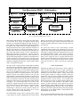
System Control and Data Acquisition of the Two New
FWCD RF Systems at DIII–D*
T.E. Harris,a J.C. Allen,a W.P. Cary,a S.W. Ferguson,b C.C. Petty,a and R.I. Pinskera
aGeneral Atomics, P.O. Box 85608, San Diego, California 92186-9784
bLawrence Livermore National Laboratory, P.O. Box 808, Livermore, California 94551-9900
ABSTRACT
The Fast Wave Current Drive (FWCD) system at DIII–D has
increased its available radio frequency (RF) power
capabilities with the addition of two new high power
transmitters along with their associated transmission line
systems. A Sun Sparc-10 workstation, functioning as the
FWCD operator console, is being used to control transmitter
operating parameters and transmission line tuning
parameters, along with acquiring data and making data
available for integration into the DIII–D data acquisition
system. Labview, a graphical user interface application, is
used to manage and control the above processes. This paper
will discuss the three primary branches of the FWCD
computer control system: transmitter control, transmission
line tuning control, and FWCD data acquisition. The main
control program developed uses VXI, GPIB, CAMAC,
Serial, and Ethernet protocols to blend the three branches
together into one cohesive system. The control of the
transmitters utilizes VXI technology to communicate with the
transmitter's digital interface. A GPIB network allows for
communication with various instruments and CAMAC crate
controllers. CAMAC crates are located at each phaseshifter/stub-tuner station and are used to digitize transmission
line parameters along with transmission line fault detection
during RF transmission. The phase-shifter/stub-tuner stations
are located through out the DIII–D facility and are controlled
from the FWCD operator console via the workstation's Serial
port. The Sun workstation has an Ethernet connection
allowing for the utilization of the DIII–D data acquisition
“Open System” architecture and of course providing
communication with the rest of the world.
INTRODUCTION
The Fast Wave Current Drive (FWCD) system at DIII–D has
been upgraded with the addition of two new high power radio
frequency (rf) transmitters along with their associated transmission line systems [1]. It was decided to have one central
control console, running one main program, for operating and
monitoring all the sub-system devices associated with the
FWCD system. A Sun Sparc-10 workstation was chosen as
the FWCD control console and LabView was chosen as the
software used to develop the main control program [2]. There
are three primary control branches in the main control program; the transmitter remote control, the transmission line
tuning control, and the data acquisition control. These three
branches use various intercommunication protocols to transfer information between hardware devices and software routines as displayed in Fig. 1. This paper will discuss the three
primary branches of the main control program and their
intercommunication protocols.
TRANSMITTER REMOTE CONTROL
The transmitter manufacturer made available a digital interface which allows the transfer of digital information representative of the transmitter state. It also provides a mode for
remote control of the transmitter. The digital interface consists of a bank of relay I/O and TTL logic devices. The control console uses VXI (VMEbus eXtensions for
Instrumentation) technology to interface with the transmitter
I/O devices via a MXI (Multi-system eXtension Interface)
bus connected directly to the console's S-bus [3]. A Tektronix
4287 “Differential 32-Channel Analog/Digital Comparator”
is used to receive information from the transmitter and a
Tektronix 4353 “32-Ch. SPST 5A General Purpose Relay
Switching” module is used to communicate digital information to the transmitter. The transmitter local control panel can
be mimicked on the control console display by selecting the
transmitter control loop in the main control program.
The transmitter mode of the main FWCD program was
designed to perform two primary functions; transmitter control and transmitter parameter changes. When in the transmitter control window, the console operator can perform the
transmitter start-up procedure. If an auxiliary system fails to
come on-line, then the problem will be indicated on the console display and the proper action can be taken to remedy the
problem. Parameter changes can be made in the transmitter
change window. One of eleven pre-programmed frequency
channels can be selected which will change the source frequency and initiate the inter-stage tuning adjustments
between the three output amplifiers for the selected transmitter. Also, pulse width limits and output power leveling can be
set. Unfortunately due to the manufacturers production
deficiencies, we have been unable to test and implement our
developed transmitter mode software.
RF TRANSMISSION LINE TUNING CONTROL
The rf transmission line connecting the rf transmitters to the
DIII–D vessel consists of twenty tuning devices, such as
*Work supported by the U.S. Department of Energy under Contract Nos. DE-AC03-89ER51114 and W-7405-ENG-48.
Fast Wave Current Drive Control Console
Sun Microsystem SPARC - 10 Workstation
MXI Bus
RS-232-> RS-485
Serial Bus
VXI
Instrumentation
Ethernet
GPIB (1,2)
DIII-D
Data Acquisition
CAMAC
Instrumentation
Digital I/O
Interface
GPIB (3)
Two FWCD
30-120 MHz 2MW
Transmitters
Transmission Line
Tuning Devices
Pulse Control
Instrumentation
Transmitter
Remote Control
Transmission Line
Tuning Control
Data Acquisition
Control
Fig. 1. FWCD inter-communication network.
phase shifters and stub tuners, that are quite large and require
a servo-motor drive system for operation. These tuning
elements are distributed throughout the DIII–D facility in
areas which are off limits during DIII–D plasma operations;
this makes local control of the servo system impossible for
tuning the transmission line system. Each tuner element has a
RS-485 serial interface for remote programming to move or
read the status of the device. Therefore, the serial (RS-232)
port on the main control console is used to communicate to
all the tuning elements via an RS-232 -> RS-485 converter.
Depending on the operating mode, the console operator can
quickly make tuning changes to optimize rf transmission line
system performance. The operator calls up the Main Tuner
window from the main program and selects the appropriate
method for changing tuner positions; the auto mode, manual
mode, or the quick tune option.
displays all the tuners' current positions. The operator can
then enter the new position values for the desired tuners and
send the command which moves all the necessary tuners at
the same time.
The auto mode is used primarily during DIII–D machine
operation and uses ASCII file read/write calls for tuner position values. In this mode the FWCD console operator can
reposition the tuners based on current DIII–D plasma parameters, a previous DIII–D shot setup, or to a vacuum conditioning setup. Based on plasma parameters, the physics
operator located in the DIII–D control room can send
programatically calculated tuning positions to an ASCII file
on the FWCD control console located in the FWCD control
room via an ethernet connection. The main control program
reads these values and moves the appropriate tuning elements
accordingly. If re-positioning based on previous shot
positions is requested, then the console operator enters the
preferred shot number and the tuners are re-positioned to the
setup for the entered shot number. When vacuum
conditioning is desired, the console operator chooses the
vacuum position option and the tuners move to their
respective positions for vacuum conditioning.
DATA ACQUISITION
Operating the FWCD system becomes a useless endeavor
without a data acquisition system to acquire FWCD data
synchronized with DIII–D experimental data. Signals
emanating from directional couplers, voltage probes, and
current probes located at strategic locations along the
transmission line network are digitized and stored in local
memory by CAMAC instrumentation. The data acquisition
program performs a direct memory access (DMA) data
transfer and processes the raw data creating a DIII–D shot
file. The shot file is then available to the DIII–D “Open
System” [4] data acquisition system. Before data can be
acquired though, all the GPIB and CAMAC instrumentation
must be setup appropriately. Therefore, there are two primary
functions of the data acquisition branch of the main program;
initialization of the GPIB/CAMAC instrumentation and
acquiring data for processing.
The manual mode is used to move a specific tuner or tuners
to any position. A window is displayed on the console which
Their are nineteen GPIB instruments that can be controlled
by the FWCD control console. This poses a small problem
The quick tune mode is most useful during vacuum
conditioning. While operating the transmitter at a specified
repetition rate, the operator can adjust the phase shifters and
stub tuners to properly match both transmission line systems
to the DIII–D tokamak vacuum. As the tuners are moving,
the transmission line positions can be monitored and the
tuners can be stopped as soon as a proper match has been
attained. Once the match has been attained, the tuner settings
can be written to an ASCII type file which can be used by
either the auto-mode or when re-entering the quick-tune
mode.
since the IEEE 488.2 (GPIB) standard limits the protocol to
only fourteen devices per GPIB bus. To accommodate the
IEEE 488.2 standard, along with device-addressing problems
we experienced during program development, we installed
three GPIB bus controller cards in the FWCD control
console; one controller card for each transmission line system
and one for the FWCD control room instrumentation. Of the
nineteen GPIB devices nine are CAMAC crates using GPIB
crate controllers. These crates are distributed among the three
transmission line tuner stations, the DIII–D pit, and the
FWCD control room. Since the distances between the GPIB
controlled CAMAC crates can span hundreds of feet,
violating the wire cable length limitations for interconnecting
GPIB devices, fiber optic extender modules are used to allow
for transmission of GPIB protocol commands. Therefore, the
operator can communicate with all CAMAC instrumentation
and either initialize the instrumentation for operation or make
instrumentation setup changes as the need arises. Besides the
CAMAC instrumentation, there are ten control instruments
located in the FWCD control room which are also GPIB
controlled. After initializing or changing setups of the GPIB
instruments, the status of the instruments is acquired and
variables within the main program needed for processing data
are defined.
The FWCD main control program and the GPIB
instrumentation are synchronized with DIII–D operations via
the DIII–D asynchronous and synchronous timing system to
ensure that FWCD raw data is meshed properly with the
DIII–D data acquisition system. The main program routinely
polls for specific DIII–D timing marks and when a specific
asynchronous timing signal is received, the FWCD console
operator will be alerted that a DIII–D plasma shot is being
queued. Once the first synchronous timing signal is received,
the main control program will launch the DIII–D shot
sequence sub-program. The displayed window on the console
displays the FWCD pulse status and any transmission line
faults which might have occurred during the rf pulse. After
the rf pulse, the digitizers are read followed by execution of
the FWCD data archiving program; this status is also
displayed on the DIII–D shot sequence window. In order for
the raw FWCD data to be processed several variables must
be defined so that the FWCD data will be in sync with the
rest of the DIII–D world. Digitizer sampling frequency, rf
instrumentation gains, and calibration codes are stored in a
labview global routine and are used when constructing the
raw data file. The FWCD data archiving program uses the
global variables to process the FWCD raw data and creates a
DIII–D shot file.
CONCLUSION
In order for the main program to communicate with the
devices within the three primary branches, various
intercommunication protocols are supported. A VXI-MXI
interface is used to link the FWCD control console to the two
rf transmitter control interfaces via two VXI chassis
connected to a MXI bus [3]. CAMAC instrumentation is used
to monitor DIII–D shot timing sequencing and acquire rf
data. The IEEE 488.2 GPIB protocol is used for data I/O
transfer from both CAMAC crates and pulse control
instrumentation to the FWCD control console. The control
console's Serial port is used to communicate with the
transmission line tuning elements. And the console's ethernet
port is used to communicate with the DIII–D data acquisition
“Open System” architecture [4].
As with any software development endeavor of this
magnitude, there are always version upgrades. This paper
discussed is what would amount to version one of the DIII–D
FWCD control software. Like any other version one software
package, there are many needs for improvement. During the
past year of DIII–D operations, the FWCD control software
was thoroughly tested and areas for improvement
documented. Much of the developed improvements were
realized as a better understanding of the labview
programming environment and of the use of multiple intercommunication protocols were achieved.
REFERENCES
[1] J.S. deGrassie, et al. “4 MW upgrade of FWCD on DIII–D,” in
Proc. 15th IEEE/NPSS Symp. on Fusion Engineering, vol. II
p. 1073, 1993.
[2] W.P. Cary, et al., “ICH rf system data acquisition and real time
control using a microcomputer system,” in Proc. of the 15th
IEEE/NPSS Symp. on Fusion Engineering, vol. II p. 547, 1993.
[3] National Instruments, “VXI-MXI User Manual,” October 1993,
p. 1–1.
[4] P.A. Henline, “Use of open systems for control, analysis, and
data acquisition of the DIII–D tokamak,” in Proc. of the 15th
IEEE/NPSS Symp. on Fusion Engineering, vol. I p. 127, 1993.