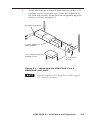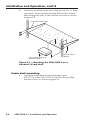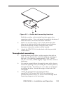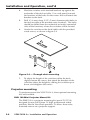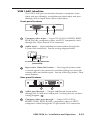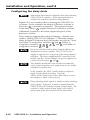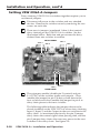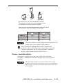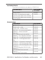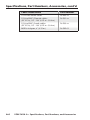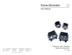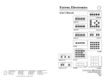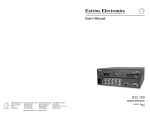
1
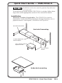
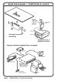
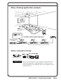
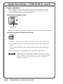
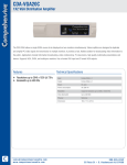
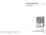
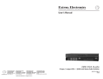
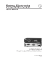
User’s Manual
VSW 2VGA A
2-Input, 1-output VGA and Audio Switcher
68-1111-01 Rev. A
09 05
Precautions
Safety Instructions • English
This symbol is intended to alert the user of important
operating and maintenance (servicing) instructions
in the literature provided with the equipment.
This symbol is intended to alert the user of the
presence of uninsulated dangerous voltage within
the product’s enclosure that may present a risk of
electric shock.
Caution
Read Instructions • Read and understand all safety and operating
instructions before using the equipment.
Retain Instructions • The safety instructions should be kept for future
reference.
Follow Warnings • Follow all warnings and instructions marked on the
equipment or in the user information.
Avoid Attachments • Do not use tools or attachments that are not
recommended by the equipment manufacturer because they may be
hazardous.
Consignes de Sécurité • Français
Ce symbole sert à avertir l’utilisateur que la
documentation fournie avec le matériel contient des
instructions importantes concernant l’exploitation et
la maintenance (réparation).
Ce symbole sert à avertir l’utilisateur de la présence
dans le boîtier de l’appareil de tensions dangereuses
non isolées posant des risques d’électrocution.
Attention
Lire les instructions• Prendre connaissance de toutes les consignes de
sécurité et d’exploitation avant d’utiliser le matériel.
Conserver les instructions• Ranger les consignes de sécurité afin de pouvoir
les consulter à l’avenir.
Respecter les avertissements • Observer tous les avertissements et consignes
marqués sur le matériel ou présentés dans la documentation utilisateur.
Eviter les pièces de fixation • Ne pas utiliser de pièces de fixation ni d’outils
non recommandés par le fabricant du matériel car cela risquerait de poser
certains dangers.
Sicherheitsanleitungen • Deutsch
Dieses Symbol soll dem Benutzer in der im
Lieferumfang enthaltenen Dokumentation
besonders wichtige Hinweise zur Bedienung und
Wartung (Instandhaltung) geben.
Dieses Symbol soll den Benutzer darauf aufmerksam
machen, daß im Inneren des Gehäuses dieses
Produktes gefährliche Spannungen, die nicht isoliert
sind und die einen elektrischen Schock verursachen
können, herrschen.
Achtung
Lesen der Anleitungen • Bevor Sie das Gerät zum ersten Mal verwenden,
sollten Sie alle Sicherheits-und Bedienungsanleitungen genau durchlesen
und verstehen.
Aufbewahren der Anleitungen • Die Hinweise zur elektrischen Sicherheit
des Produktes sollten Sie aufbewahren, damit Sie im Bedarfsfall darauf
zurückgreifen können.
Befolgen der Warnhinweise • Befolgen Sie alle Warnhinweise und
Anleitungen auf dem Gerät oder in der Benutzerdokumentation.
Keine Zusatzgeräte • Verwenden Sie keine Werkzeuge oder Zusatzgeräte,
die nicht ausdrücklich vom Hersteller empfohlen wurden, da diese eine
Gefahrenquelle darstellen können.
Instrucciones de seguridad • Español
Este símbolo se utiliza para advertir al usuario
sobre instrucciones importantes de operación y
mantenimiento (o cambio de partes) que se desean
destacar en el contenido de la documentación
suministrada con los equipos.
Este símbolo se utiliza para advertir al usuario sobre
la presencia de elementos con voltaje peligroso sin
protección aislante, que puedan encontrarse dentro
de la caja o alojamiento del producto, y que puedan
representar riesgo de electrocución.
Precaucion
Leer las instrucciones • Leer y analizar todas las instrucciones de operación y
seguridad, antes de usar el equipo.
Conservar las instrucciones • Conservar las instrucciones de seguridad para
futura consulta.
Obedecer las advertencias • Todas las advertencias e instrucciones marcadas
en el equipo o en la documentación del usuario, deben ser obedecidas.
Evitar el uso de accesorios • No usar herramientas o accesorios que no
sean especificamente recomendados por el fabricante, ya que podrian
implicar riesgos.
Warning
Power sources • This equipment should be operated only from the power source
indicated on the product. This equipment is intended to be used with a main power
system with a grounded (neutral) conductor. The third (grounding) pin is a safety
feature, do not attempt to bypass or disable it.
Power disconnection • To remove power from the equipment safely, remove all power
cords from the rear of the equipment, or the desktop power module (if detachable),
or from the power source receptacle (wall plug).
Power cord protection • Power cords should be routed so that they are not likely to be
stepped on or pinched by items placed upon or against them.
Servicing • Refer all servicing to qualified service personnel. There are no userserviceable parts inside. To prevent the risk of shock, do not attempt to service
this equipment yourself because opening or removing covers may expose you to
dangerous voltage or other hazards.
Slots and openings • If the equipment has slots or holes in the enclosure, these are
provided to prevent overheating of sensitive components inside. These openings
must never be blocked by other objects.
Lithium battery • There is a danger of explosion if battery is incorrectly
replaced. Replace it only with the same or equivalent type recommended by
the manufacturer. Dispose of used batteries according to the manufacturer’s
instructions.
Avertissement
Alimentations• Ne faire fonctionner ce matériel qu’avec la source d’alimentation
indiquée sur l’appareil. Ce matériel doit être utilisé avec une alimentation principale
comportant un fil de terre (neutre). Le troisième contact (de mise à la terre) constitue
un dispositif de sécurité : n’essayez pas de la contourner ni de la désactiver.
Déconnexion de l’alimentation• Pour mettre le matériel hors tension sans danger,
déconnectez tous les cordons d’alimentation de l’arrière de l’appareil ou du module
d’alimentation de bureau (s’il est amovible) ou encore de la prise secteur.
Protection du cordon d’alimentation • Acheminer les cordons d’alimentation de
manière à ce que personne ne risque de marcher dessus et à ce qu’ils ne soient pas
écrasés ou pincés par des objets.
Réparation-maintenance • Faire exécuter toutes les interventions de réparationmaintenance par un technicien qualifié. Aucun des éléments internes ne peut être
réparé par l’utilisateur. Afin d’éviter tout danger d’électrocution, l’utilisateur ne doit
pas essayer de procéder lui-même à ces opérations car l’ouverture ou le retrait des
couvercles risquent de l’exposer à de hautes tensions et autres dangers.
Fentes et orifices • Si le boîtier de l’appareil comporte des fentes ou des orifices, ceux-ci
servent à empêcher les composants internes sensibles de surchauffer. Ces ouvertures
ne doivent jamais être bloquées par des objets.
Lithium Batterie • Il a danger d’explosion s’ll y a remplacment incorrect de la batterie.
Remplacer uniquement avec une batterie du meme type ou d’un ype equivalent
recommande par le constructeur. Mettre au reut les batteries usagees conformement
aux instructions du fabricant.
Vorsicht
Stromquellen • Dieses Gerät sollte nur über die auf dem Produkt angegebene
Stromquelle betrieben werden. Dieses Gerät wurde für eine Verwendung mit einer
Hauptstromleitung mit einem geerdeten (neutralen) Leiter konzipiert. Der dritte
Kontakt ist für einen Erdanschluß, und stellt eine Sicherheitsfunktion dar. Diese
sollte nicht umgangen oder außer Betrieb gesetzt werden.
Stromunterbrechung • Um das Gerät auf sichere Weise vom Netz zu trennen, sollten
Sie alle Netzkabel aus der Rückseite des Gerätes, aus der externen Stomversorgung
(falls dies möglich ist) oder aus der Wandsteckdose ziehen.
Schutz des Netzkabels • Netzkabel sollten stets so verlegt werden, daß sie nicht im
Weg liegen und niemand darauf treten kann oder Objekte darauf- oder unmittelbar
dagegengestellt werden können.
Wartung • Alle Wartungsmaßnahmen sollten nur von qualifiziertem Servicepersonal
durchgeführt werden. Die internen Komponenten des Gerätes sind wartungsfrei.
Zur Vermeidung eines elektrischen Schocks versuchen Sie in keinem Fall, dieses
Gerät selbst öffnen, da beim Entfernen der Abdeckungen die Gefahr eines
elektrischen Schlags und/oder andere Gefahren bestehen.
Schlitze und Öffnungen • Wenn das Gerät Schlitze oder Löcher im Gehäuse aufweist,
dienen diese zur Vermeidung einer Überhitzung der empfindlichen Teile im
Inneren. Diese Öffnungen dürfen niemals von anderen Objekten blockiert werden.
Litium-Batterie • Explosionsgefahr, falls die Batterie nicht richtig ersetzt
wird. Ersetzen Sie verbrauchte Batterien nur durch den gleichen oder einen
vergleichbaren Batterietyp, der auch vom Hersteller empfohlen wird. Entsorgen Sie
verbrauchte Batterien bitte gemäß den Herstelleranweisungen.
Advertencia
Alimentación eléctrica • Este equipo debe conectarse únicamente a la fuente/tipo
de alimentación eléctrica indicada en el mismo. La alimentación eléctrica de este
equipo debe provenir de un sistema de distribución general con conductor neutro
a tierra. La tercera pata (puesta a tierra) es una medida de seguridad, no puentearia
ni eliminaria.
Desconexión de alimentación eléctrica • Para desconectar con seguridad la acometida
de alimentación eléctrica al equipo, desenchufar todos los cables de alimentación
en el panel trasero del equipo, o desenchufar el módulo de alimentación (si fuera
independiente), o desenchufar el cable del receptáculo de la pared.
Protección del cables de alimentación • Los cables de alimentación eléctrica se deben
instalar en lugares donde no sean pisados ni apretados por objetos que se puedan
apoyar sobre ellos.
Reparaciones/mantenimiento • Solicitar siempre los servicios técnicos de personal
calificado. En el interior no hay partes a las que el usuario deba acceder. Para evitar
riesgo de electrocución, no intentar personalmente la reparación/mantenimiento
de este equipo, ya que al abrir o extraer las tapas puede quedar expuesto a voltajes
peligrosos u otros riesgos.
Ranuras y aberturas • Si el equipo posee ranuras o orificios en su caja/alojamiento,
es para evitar el sobrecalientamiento de componentes internos sensibles. Estas
aberturas nunca se deben obstruir con otros objetos.
Batería de litio • Existe riesgo de explosión si esta batería se coloca en la posición
incorrecta. Cambiar esta batería únicamente con el mismo tipo (o su equivalente)
recomendado por el fabricante. Desachar las baterías usadas siguiendo las
instrucciones del fabricante.
安全须知 • 中文
这个符号提示用户该设备用户手册中
有重要的操作和维护说明。
这个符号警告用户该设备机壳内有
露的危险电压,有触电危险。
注意
阅读说明书 • 用户使用该设备前必须阅读并理解所有
安全和使用说明。
保存说明书 • 用户应保存安全说明书以备将来使用。
遵守警告 • 用户应遵守产品和用户指南上的所有安全
和操作说明。
避免追加 • 不要使用该产品厂商没有推荐的工具或追
加设备,以避免危险。
警告
电源 • 该设备只能使用产品上标明的电源。 设备必须
使用有地线的供电系统供电。 第三条线(地线)是
安全设施,不能不用或跳过 。
拔掉电源 • 为安全地从设备拔掉电源,请拔掉所有设
备后或桌面电源的电源线,或任何接到市电系统的
电源线。
电源线保护 • 妥善布线, 避免被踩踏,或重物挤压。
维护 • 所有维修必须由认证的维修人员进行。 设备内
部没有用户可以更换的零件。为避免出现触电危险
不要自己试图打开设备盖子维修该设备。
通风孔 • 有些设备机壳上有通风槽或孔,它们是用来
防止机内敏感元件过热。 不要用任何东西挡住通
风孔。
锂电池 • 不正确的更换电池会有爆炸的危险。必须使用
与厂家推荐的相同或相近型号的电池。按照生产厂
的建议处理废弃电池。
Precautions, cont’d
Quick Start Guide — VSW 2VGA A
Installation and service must be performed by authorized
personnel only.
To install 1inchQuarterRackVersaToolsShelf
and set up the Extron VSW 2VGA A switcher, follow these
steps and see the appropriate section of this manual for details:
Installation
Mount the switcher (if applicable). The VSW 2VGA A can be
mounted in a rack shelf, under furniture, through furniture, or to a
projector mount. See chapter 2, Installation and Operation.
VersaTools Rack Shelf
Rack shelf mounting
1/4 Rack Width Front
False Faceplate
Use 2 mounting holes on
opposite corners.
(2) 4-40 x 3/16"
Screws
Under-desk mounting
VSW 2VGA A • Quick Start Guide
QS-1
Quick Start Guide — VSW 2VGA A, cont’d
ProjectorMountPMK200
Extron
PMK 200
Mounting
Bolt
1
2
T
U
P
IN
1
T
U
P
IN
2
W
S
V
G
2V
A
A
Projector
Mounting
Bracket
Ceiling
Projector
Through-furniture
mounting
Attachment to a
projector mount
Signal switcher application example
Projector
Local Monitor
UT
INP
2
A
GA
W
U
INP
Sound System
T1
VS
2V
1
2
Extron
VSW 2VGA A
VGA Switcher
Two Button
Contact Closure
QS-2
VSW 2VGA A • Quick Start Guide
Laptop
PC
Daisy chaining application example
Extron
VSW 1 AAP
Extron
VSW 2VGA A
VGA Switcher
SHOW ME
COMPUTER
AUDIO
VSW I AAP
Extron
VSW I AAP
Expandable, economical presentation chain for
Conference rooms and library study rooms.
Extron’s pre-made
VGA with audio cable
assemblies.
AUDIO
COMPUTER
VSW I AAP
COMPUTER
AUDIO
In 1
INPUT 1
INPUT 2
1
2
In 2
VSW I AAP
COMPUTER
INPUT 1
In 1
INPUT 2
1
2
Out
In 2
INPUT 1
VSW 2VGA A
INPUT 2
1
2
VSW I AAP
Out
In 2
In 1
INPUT 1
VSW 2VGA A
INPUT 2
1
2
Out
VSW 2VGA A
VSW 2VGA A
VSW 2VGA A
VSW 2VGA A
AUDIO
VSW I
AAP
VSW I
AAP
VSW I
AAP
Projector
SHOW ME
SHOW ME
SHOW ME
VSW 2VGA A
Extron’s pre-made VGA with audio cable assemblies
Power connector wiring
0.2” (5 mm) MAX
+
SECTION A–A
CAUTION
When connecting the power supply, voltage polarity is
extremely important. Applying power with incorrect
voltage polarity could damage the power supply and the
VSW 2VGA A.
VSW 2VGA A • Quick Start Guide
QS-3
Quick Start Guide — VSW 2VGA A, cont’d
Input selection
The switcher's inputs are selected using the front panel's Input
Select toggle switch or the rear panel's 3-pole Contact closure/
Autoswitching captive screw connector.
Input Select toggle switch
1
2
Input Select
Toggle Switch
Move this switch up to select Input 1; move it down to select Input 2.
Contact closure and Autoswitching
CONTACT
1
2
AUTO-SW
Connect a contact closure device to this captive screw connector..
• Pin 1 selects Input 1 when momentarily connected to ground
(pin 3).
• Pin 2 selects Input 2 when momentarily connected to ground
(pin 3).
• Pin 3 connects to the ground wire (equipment ground).
Simultaneously connecting both pins 1 and 2 to ground
(pin 3) using a contact closure device turns autoswitching
mode on. The Input Select toggle switch is disabled in
Autoswitch mode.
QS-4
VSW 2VGA A • Quick Start Guide
Table of Contents
Chapter One • Introduction
................................................... 1-1
About this Manual .................................................................... 1-2
About the VSW 2VGA A .......................................................... 1-2
Features ........................................................................................ 1-2
Chapter Two • Installation and Operation
................. 2-1
Installation Overview ............................................................... 2-2
Mounting the VSW 2VGA A ................................................... 2-2
Rack shelf mounting .............................................................. 2-2
Under-desk mounting ............................................................ 2-4
Through-desk mounting........................................................ 2-5
Projector mounting ................................................................ 2-6
PMK 100 Mini Projector Mount Kit .......................................2-6
PMK 250 Projector Mount Kit ................................................2-7
PMK 300 Projector Mount Kit ................................................2-9
Rear Panel Features and Cabling ........................................ 2-11
Front Panel Features and Operation ................................. 2-13
Daisy Chaining the VSW 2VGA A ....................................... 2-14
VSW I AAP interface ............................................................ 2-15
Front panel features .............................................................2-15
Rear panel features ..............................................................2-15
Configuring the daisy chain ................................................ 2-16
Setting VSW 2VGA A Jumpers ............................................ 2-18
Power considerations .......................................................... 2-19
Appendix A • Specifications, Part Numbers,
and Accessories ..............................................................................A-1
Specifications ..............................................................................A-2
Included Parts .............................................................................A-5
Accessories ...................................................................................A-5
All trademarks mentioned in this manual are the properties of their respective owners.
68-1111-01 A
09 05
VSW 2VGA A • Table of Contents
i
Table of Contents, cont’d
ii
VSW 2VGA A • Table of Contents
VSW 2VGA A
1
Chapter One
Introduction
About this Manual
About the VSW 2VGA A
Features
Introduction
About this Manual
This manual contains information about the Extron
VSW 2VGA A switcher. The terms “VSW 2VGA A” and
“switcher” are used interchangeably in this manual. The Extron
VSW I AAP interface (part # 70-529-xx), an optional accessory
used when several VSW 2VGA A switchers are daisy chained
together, is also discussed.
About the VSW 2VGA A
The Extron VSW 2VGA A is a compact and economical twoinput, one-output VGA switcher with unbalanced stereo
audio and 300 MHz (-3 dB) video bandwidth. It accepts two
VGA-UXGA, RGBHV, RGBS, RGsB, RsGsBs, component video,
or HDTV component video inputs. The switcher has two
unbalanced stereo audio inputs and one unbalanced stereo
audio output. It also features a buffered local monitor output
for Input 1.
A front panel toggle switch, a contact closure controller, or the
autoswitching option can be used for input selection.
Features
Autoswitching ability — The VSW 2VGA A can detect active
sync signals and automatically switch to the active input.
Furniture mountable — The VSW 2VGA A can be mounted
on a rack shelf, under a desk or podium, through a desk
or furniture, or to a projector mount, using optional
hardware.
Daisy chaining — Multiple VSW 2VGA A switchers can be
daisy chained together to form a presentation system.
Each switcher can then be separately controlled through
an Extron VSW I AAP interface.
Stereo audio — Unbalanced stereo audio inputs and outputs on
3.5 mm stereo mini jacks
1-2
VSW 2VGA A • Introduction
VSW 2VGA A
2
Chapter Two
Installation and Operation
Installation Overview
Mounting the VSW 2VGA A
Rear Panel Features and Cabling
Front Panel Features and Operation
Daisy Chaining the VSW 2VGA A
Setting VSW 2VGA Jumpers
Installation and Operation
Installation Overview
To install and set up the VSW 2VGA A for operation, follow
these steps:
1
Turn all of the equipment off. Make sure that the
video and audio sources (computers, stereos, tape
decks, or other devices), the VSW 2VGA A,
the output devices (projectors, speakers), and the contact
closure control device are all turned off and
disconnected from the power source.
2
Mount the switcher. See “Mounting the VSW 2VGA A” in
this chapter.
3
Attach the cables. See “Rear Panel Features and Cabling”
in this chapter.
4
Connect power cords and turn on the devices in the
following order: output devices, contact closure controller,
VSW 2VGA A switcher, and input devices.
5
Select an input using the front panel input toggle switch or
the contact closure controller.
6
The image should now display, and sound should be
audible. If not, ensure that all devices are plugged in and
receiving power. Check the cabling and make adjustments
as needed. Select a different input to check for a picture
and sound. See “Troubleshooting” in this chapter.
Mounting the VSW 2VGA A
When mounting the switcher, take cabling and power
availability into consideration. Select rack shelf, under-desk
(optional), through-desk (optional), or projector bracket
(optional) mounting. Follow the appropriate mounting
procedure on the following pages.
Rack shelf mounting
2-2
1.
If feet were installed on the bottom of the switcher, remove
them.
2.
Mount the VSW 2VGA A on a VersaTools® 19" 1U Rack
Shelf (part #60-190-20 or #60-604-20), a 1U 6" Deep
Rack Shelf (part #60-190-01 or 60-604-10), or a standard
Universal 1U Rack Shelf (part #60-190-01 or #60-604-01).
On the standard rack shelf, the switcher mounts in one
of four locations to the rear of the rack or in one of four
locations to the front of the rack.
VSW 2VGA A • Installation and Operation
1inchQuarterRackVersaToolsShelf
3.
Attach the switcher to the rack shelf using two 4-40 x 3/16"
machine screws. Insert the screws from the underside of
the shelf and securely fasten them into diagonally opposite
corners, as shown in figure 2-1.
VersaTools Rack Shelf
1/4 Rack Width Front
False Faceplate
Use 2 mounting holes on
opposite corners.
(2) 4-40 x 3/16"
Screws
Figure 2-1 — Mounting the VSW 2VGA A on a
VersaTools rack shelf
Since the switcher is 1.0" high, there will be a gap of
0.75" above the switcher.
VSW 2VGA A • Installation and Operation
2-3
Installation and Operation, cont’d
4.
1inchBoxQuarterSizeStandardShelf
Attach the rack shelf to the rack using four 10-32 x ¾” bolts
(provided). Insert the bolts through #10 beveled washers,
then through the holes in the rack ears and rack, as shown
in figure 2-2.
1U Universal Rack Shelf
Use 2 mounting holes on
opposite corners.
(2) 4-40 x 3/16"
Screws
Figure 2-2 — Mounting the VSW 2VGA A on a
standard 1U rack shelf
Under-desk mounting
1.
2-4
Attach the under-desk mounting brackets (part
#70-077-01) to the VSW 2VGA A with the four provided
machine screws, as shown in figure 2-3.
VSW 2VGA A • Installation and Operation
Figure 2-3 — Under-desk mounting brackets
Hold the switcher with attached brackets against the
mounting surface. Use a soft pencil to mark the location of
holes for screws on the desk or other furniture.
3.
Drill 1/4" (6.4 mm) deep, 3/32" (2 mm) diameter pilot
holes in the table or desk at the marked screw locations
from the underside/inside (concealed side) of the
furniture, where the switcher will be located.
4.
Attach the VSW 2VGA A to the desk with the provided
wood screws.
Through-desk mounting
1.
Hold the front panel of the switcher against the desk or
table. Use a soft pencil to mark the rough-in opening on
the desk. The opening, approximately 1.125" x 4.425"
(2.8 cm x 11.2 cm), will be slightly larger than the switcher
enclosure.
2.
Cut out the material from the rough-in area with a jigsaw.
Check the opening size by inserting the switcher part way
through the hole. If needed, use a saw, file, or sandpaper
to enlarge the hole. Smooth the edges of the hole with
sandpaper.
3.
Attach the through-desk mounting brackets
(part #70-077-02) to the VSW 2VGA A with the four
provided machine screws, as shown in the through-desk
mounting diagram on the next page.
VSW 2VGA A • Installation and Operation
2-5
Installation and Operation, cont’d
Hold the switcher with attached brackets up against the
underside of the desk or table. Use a soft pencil to mark
the locations of the holes for the screws that will attach the
brackets to the desk.
5.
Drill ¼" (6 mm) deep, 3/32" (2 mm) diameter pilot holes in
the desk or table at the marked screw locations. The holes
should be drilled from the underside or inside (concealed
side) of the furniture, where the switcher will be located.
6.
Attach the switcher to the desk/table with the provided
wood screws, as shown in figure 2-4.
1
2
IN
T
U
P
1
IN
T
U
P
2
W
S
V
G
2V
A
A
4.
Figure 2-4 — Through-desk mounting
7.
To adjust the height of the switcher within the desk,
slightly loosen the screws that attach the brackets to the
switcher, adjust the height by sliding the switcher up or
down, and retighten the screws.
Projector mounting
To projector-mount the VSW 2VGA A, three optional mounting
kits are available.
PMK 100 Mini Projector Mount Kit
The PMK 100 is a projector mounting kit (part # 70-217-01)
designed for use with Extron 1U high, quarter-rack width
products like the VersaTools products. It allows them to be
mounted near or on a projector support.
2-6
VSW 2VGA A • Installation and Operation
Follow these steps to projector-mount the VSW 2VGA A using
the PMK 100 kit:
1.
If rubber feet were previously attached to the bottom of the
unit, remove them.
2.
Remove the two screws from one side of the switcher.
ProjectorMountPMK200
Retain
the screws for possible later reassembly.
3.
Attach the projector mounting bracket to the side of the
unit, using the provided machine screws.
Extron
PMK 200
Projector
Mounting
Bracket
Mounting
Bolt
Ceiling
Projector
Figure 2-5 — Projector-mounting the VSW 2VGA A
using the PMK 200 Projector Mount kit
4.
Secure the unit to a projector mount or other surface by
inserting the mounting bolt through the bracket’s slotted
hole.
PMK 250 Projector Mount Kit
The PMK 250 Low Profile Projector Mount Kit is an aboveprojector mounting kit that attaches to a 1" to 2" diameter
projector mounting pole. It can hold more than one device,
in a variety of sizes. The PMK 250 is available in black (part
#70-526-02) or white (part #70-526-03).
Follow these steps to mount the VSW 2VGA A on the PMK 250
bracket.
1.
Remove the front panel from the PMK 250, using an Extron
Tweeker or other small Philips screwdriver. (Retain the
four screws to reattach the plate when finished.)
2.
Remove the protective backing from the self-adhesive
rubber pad, and place the pad on the PMK 250 mount
plate, centering it between the two holes (see figure 2-6).
3.
Remove any rubber feet from the bottom of the switcher.
VSW 2VGA A • Installation and Operation
2-7
Installation and Operation, cont’d
4.
Secure the switcher to one side of the mounting bracket,
using two of the supplied 4-40 x 3/16 screws in opposite
(diagonal) corners.
5.
Using the two included tie wraps, strap the switcher power
supply to the PMK 250 bracket.
6.
Place the bracket around the projector ceiling mounting
pole as shown in figure 2-6.
Rubber Pad
U-bolt
Extron
PMK 250
Mounted
Extron Product
Projector Mount Kit
Plastic Tie
Extron
Power Supply
Front Plate
Cover Sheet
Figure 2-6 — Projector-mounting the VSW 2VGA A
using the PMK 250 Projector Mount kit
7.
Insert the two legs of the provided square U-bolt through
the slotted holes on the back side of the bracket mount
plate, place the two legs around the ceiling pole, then insert
them through the round holes on the backing brace.
• For a typical (1.5" to 2.0" diameter) pole — You can use
the supplied square U-bolt, which fits a typical ceiling
pole.
• For a smaller pole — Locally obtain a square U-bolt
that fits your ceiling pole. The slotted holes on the
bracket can accommodate a square U-bolt for pole sizes
from 1.0" to 2.0" in diameter.
8.
2-8
Move the PMK 250 up to the desired location on the ceiling
pole, as close to the ceiling as desired.
VSW 2VGA A • Installation and Operation
9.
Secure the back brace to the square U-bolt using the
included hex nuts, washers, and lock washers. Tighten the
hex nuts securely.
Be sure to tighten the hex nuts securely enough that the
PMK 250 does not slide down the ceiling pole. A socket
wrench is recommended to tighten the hex nuts.
10.
Secure the front panel to the mounting tray with four of the
included #6 screws.
11.
If desired, choose one of the provided four sizes of selfadhesive cover sheets, and apply it to the underside of the
mounting tray.
PMK 300 Projector Mount Kit
The PMK 300 Multi-Product Projector Mount Kit (#70-374-01)
mounts up to three quarter-rack width products to a projector
ceiling mount pole. The VSW 2VGA A can be mounted above
the display device with the front panel facing either down or
up. The quarter rack width plate can also be used to mount the
switcher's external desktop power supply.
Follow these steps to projector-mount the switcher using the
PMK 300:
1.
If necessary, remove the feet from the bottom of the
switcher.
2.
Mount the switcher to one of the bracket’s three mounting
plates. It can be vertically mounted facing either up or
down, whichever is more convenient. See figure 2-7.
• On the side mounting plates, the switcher is typically
mounted on the outside of the bracket.
On the front mounting plate, the device is typically
mounted on the inside of the bracket.
• For the VSW 2VGA A unit, use two of the supplied
4-40 x 3/16 screws in opposite (diagonal) corners to
secure the device to the bracket.
For the switcher's power supply, use the two included
tie wraps to strap the power supply to the bracket.
3.
Place the U-bolt around the ceiling pole and insert the two
legs of the U-bolt through the slotted holes on the bracket’s
mounting plate, then through the round holes on the
backing brace.
• For a typical (1.5" to 2.0" diameter) pole — You can use
the supplied square U-bolt, which fits a typical ceiling
pole.
VSW 2VGA A • Installation and Operation
2-9
Installation and Operation, cont’d
• For a smaller or larger pole — Locally obtain a square
U-bolt that fits your ceiling pole. The slotted holes on
the bracket can accommodate a square U-bolt for pole
sizes from 1.0" to 2.5" in diameter.
4.
Secure the bracket to the U-bolt with the included hex
nuts, washers, and lock washers. Tighten the hex nuts just
enough that they can be loosened by hand.
Rubber Pad
U-Bolt
Multi Product
Projector Mounting Kit
Figure 2-7 — Projector-mounting the VSW 2VGA A
using the PMK 300 Projector Mount Kit
2-10
VSW 2VGA A • Installation and Operation
Rear Panel Features and Cabling
POWER
12V
.1A MAX
LOOP THRU
OUTPUT
VSW 2VGA A
AUD OUT
INPUT 1
1
1
2
CONTACT
1
2
AUTO-SW
3
4
5
Power connector (Power) — Connect the included 12 VDC
external power supply to the 2-pole 3.5 mm captive screw
connector. Be careful to observe the correct polarity.
Smooth
Ridges
A
A
SECTION A–A
0.2” (5 mm)
Power Supply
Output Cord
Captive Screw
Connector
The two power cord wires must be kept separate
while the power supply is plugged in. Remove
power before wiring.
CAUTION
When you are connecting the power supply, voltage
polarity is extremely important. Applying power
with incorrect voltage polarity could damage the
power supply and the VSW 2VGA A. Identify the
power cord negative (ground) lead by the ridges on
the side of the cord or a black heat shrink wrapping
around it.
Strip the jacket to expose 0.2 inches (5 mm) of the
conductors. Do not tin the stripped power supply leads
before installing the captive screw connector. Tinned
wires are not as secure in the captive screw connectors
and could be pulled out.
To verify the polarity before connection, check the no load
power supply output with a voltmeter.
VSW 2VGA A • Installation and Operation
2-11
Installation and Operation, cont’d
2
Input 1 loop-through (Loop Thru Input 1) — 15-pin HD female
VGA connector for buffered local monitor output from Input 1
3
Output — 15-pin HD female VGA connector for output from
Input 1 or Input 2. The output video type follows input type
and is either VGA-UXGA, RGBHV, RGBS, RGsB, RsGsBs,
component video, or HDTV component video.
RGsB and RsGsBs inputs and outputs occur in manual
mode only. Autoswitching requires TTL level sync on
pin 13 of the 15-pin HD connector.
4
Audio Output (Aud Out) — Unbalanced stereo audio is output
from this 3.5 mm mini audio jack. Wire the male audio plug, as
shown below.
Tip (L)
Ring (R)
Sleeve ( )
3.5 mm Stereo Plug Connector
(unbalanced)
5
Contact closure/Autoswitching (Contact/Auto-SW) —
Connect a contact closure device to this 3.5 mm, 3-pole captive
screw connector.
•
Pin 1 selects Input 1 when momentarily connected to
ground (pin 3).
•
Pin 2 selects Input 2 when momentarily connected to
ground (pin 3).
•
Pin 3 connects to the ground wire (equipment ground).
CONTACT
1
2
AUTO-SW
Simultaneously connecting both pins 1 and 2 to
ground (pin 3) using a contact closure device turns
autoswitching mode on.
•
Pins 1, 2, and 3 when jumpered/shorted together turn the
autoswitching mode on. When the autoswitching mode
is on, the switcher automatically switches to the input that
has an active sync signal. See the above diagram.
If both inputs have an active sync signal present, input 2 is
selected, and the input 2 LED indicator lights. If no active
2-12
VSW 2VGA A • Installation and Operation
sync signal is present, the input 1 LED indicator still lights
to indicate that the unit is still powered on.
When autoswitch mode is active, both daisy chaining
and the front panel's input toggle switch are disabled,
and the input cannot be manually switched. Any
attempt to toggle the switch while the switcher is in
this mode results in the flashing of the currently active
input's LED indicator. Contact closure is also disabled
while in autoswitch mode.
Front Panel Features and Operation
INPUT 1
1
2
INPUT 2
1
2
VSW 2VGA A
3
4
5
6
7
1
Input 1 LED indicator — This LED lights green whenever
Input 1 (video and audio) is selected.
2
Input 2 LED indicator — This LED lights green whenever
Input 2 (video and audio) is selected.
The LEDs 1 and 2 above also serve as power up
indicators. When the switcher is powered up, the
selected input's LED lights green.
3
Input select toggle switch — Toggling this switch up selects
Input 1; toggling it down selects Input 2.
4
Input 1 video — Input VGA-UXGA, RGBHV, RGBS, RGsB,
RsGsBs, component video, or HDTV component video through
this 15-pin female VGA connector.
5
Input 1 audio — Input unbalanced
stereo audio through this 3.5 mm mini
audio jack. See the diagram at right.
6
3.5 mm Stereo Plug Connector
Input 2 video — Input VGA(unbalanced)
UXGA, RGBHV, RGBS, RGsB,
RsGsBs, component video, or HDTV
component video through this 15-pin female VGA connector.
7
Input 2 audio — Input unbalanced stereo audio through this
3.5 mm mini audio jack. See the previous wiring diagram ( 5 ).
Tip (L)
Ring (R)
Sleeve ( )
VSW 2VGA A • Installation and Operation
2-13
Installation and Operation, cont’d
Daisy Chaining the VSW 2VGA A
The VSW 2VGA A switchers can be daisy chained together
with each switcher's input separately fed and controlled by an
optional accessory interface, the VSW I AAP (part #70-529-xx).
The following diagram shows an example of how several such
switcher-interface combinations can be daisy chained together
in a boardroom environment.
Extron
VSW 1 AAP
Extron
VSW 2VGA A
VGA Switcher
SHOW ME
COMPUTER
AUDIO
VSW I AAP
Extron
VSW I AAP
Expandable, economical presentation chain for
Conference rooms and library study rooms.
Extron’s pre-made
VGA with audio cable
assemblies.
COMPUTER
VSW I AAP
COMPUTER
AUDIO
In 1
INPUT 1
In 2
INPUT 2
1
2
VSW I AAP
INPUT 1
COMPUTER
In 1
INPUT 2
1
2
Out
In 2
INPUT 1
VSW 2VGA A
INPUT 2
1
2
VSW 2VGA A
VSW I AAP
Out
In 2
In 1
INPUT 1
INPUT 2
1
2
Out
VSW 2VGA A
VSW 2VGA A
VSW 2VGA A
VSW 2VGA A
AUDIO
VSW I
AAP
VSW I
AAP
VSW I
AAP
Projector
SHOW ME
SHOW ME
SHOW ME
AUDIO
VSW 2VGA A
Extron’s pre-made VGA with audio cable assemblies
By default, all switchers are set to Input 2 as the active input;
therefore, in a daisy chain of switchers the VGA and audio
signals flow from one switcher to Input 2 of the next switcher in
the chain. The switchers are daisy chained in this fashion until
the last switcher in the daisy chain outputs to a projector and
audio amplifier.
When the user presses the "Show Me" button on the VSW I AAP
interface (see the following section, "VSW I AAP interface"),
the switcher connected to the interface selects its Input 1. This
user's VGA and audio signals flow into the daisy chain and are
routed to the projector or other output device(s).
Up to ten switchers can be daisy chained together without any
degradation in picture quality. One power supply powers up to
five switchers.
2-14
VSW 2VGA A • Installation and Operation
VSW I AAP interface
The VSW I AAP passive interface features a computer video
input and pass-through, an unbalanced stereo input and passthrough, and an input select (Show Me) button.
Front panel features
SHOW ME
AUDIO
COMPUTER
1
VSW I AAP
2
3
1
Computer video input — Input VGA-UXGA, RGBHV, RGBS,
RGsB, RsGsBs, component video, or HDTV component video
through this 15-pin female VGA connector.
2
Audio input — Input unbalanced stereo audio through this
3.5 mm mini audio jack. See the wiring diagram below.
Tip (L)
Ring (R)
Sleeve ( )
3.5 mm Stereo Plug Connector
(unbalanced)
3
Input select (Show Me) button — Pressing this button sends
a control signal to the connected switcher telling it to select the
current video and audio inputs. See the following section, "Rear
panel features".
Rear panel features
1
2
1
Audio pass-through — Output unbalanced stereo audio
through this 3.5 mm mini audio jack. See the previous section's
wiring diagram ( 2 ).
2
Computer video pass-through — Output VGA-UXGA,
RGBHV, RGBS, RGsB, RsGsBs, component video, or HDTV
component video through this 15-pin female VGA connector.
VSW 2VGA A • Installation and Operation
2-15
Installation and Operation, cont’d
Configuring the daisy chain
Autoswitch mode must be disabled when daisy chaining
VSW 2VGA A switchers. If the autoswitch mode is
enabled, the switchers cannot be daisy chained.
Figure 2-8 is an example of daisy chaining ten VSW 2VGA A
switchers. In the example, the output of the first switcher in
the chain ( 1 ) is routed to a projector. The second switcher
in the daisy chain ( 2 ) outputs to Input 2 of the first switcher.
Additional switchers in the chain output to Input 2 of the
previous switcher.
Daisy chaining requires the setting of jumpers. (See the next
section, "Setting VSW 2VGA A Jumpers".) The three jumper
tables in figure 2-8 indicate how the jumpers must be set. Note
that Table 1 is assigned to switchers 1 and 6 ; Table 2 is
assigned to switchers 2 , 3 , 4 , 7 , 8 , and 9 ; and Table 3 is
assigned to switchers 5 and 10 .
Up to ten switchers can be daisy chained without any
degradation in picure quality. One 12 VDC power
supply is required for every group of five daisy chained
switchers. The power supply must be connected to the
middle switcher. In the example, the power supplies are
connected to switchers 3 and 8 .
The installer should label each switcher in numerical
order so that its position in a daisy chain can be readily
identified at a future date.
In the example, the VSW I AAP interfaces output to
Input 1 of its attached switcher. Press the
VSW I AAP's Input select (Show Me) button to route
the interface's input to the projector.
Daisy chaining audio signals is similar to daisy chaining
video signals. In figure 2-8, audio is output from the
VSW I AAP to the switcher's Input 1 audio input. The
switcher's audio output is then input to the Input 2
audio input of the next switcher in the daisy chain.
2-16
VSW 2VGA A • Installation and Operation
VSW 2VGA A • Installation and Operation
2-17
SHOW ME
VSW I AAP
VSW 2VGA A
INPUT 2
SHOW ME
VSW I AAP
INPUT 1
In 1
AUDIO
VSW 2VGA A
INPUT 2
Closed
Closed
5
6
Table 3
Closed
Open
Closed
2
3
Closed
4
Setting
Out
1
5
VSW 2VGA A
1
2
COMPUTER
VSW I AAP
10
Out
Jumper
In 2
INPUT 1
In 1
AUDIO
VSW 2VGA A
1
2
COMPUTER
VSW I AAP
In 2
In 2
INPUT 1
In 1
AUDIO
SHOW ME
VSW I AAP
VSW 2VGA A
INPUT 2
SHOW ME
VSW I AAP
INPUT 1
In 1
AUDIO
VSW 2VGA A
INPUT 2
Out
Out
In 1
INPUT 1
SHOW ME
VSW I AAP
SHOW ME
VSW I AAP
INPUT 1
In 1
AUDIO
VSW 2VGA A
INPUT 2
Closed
Closed
5
6
Table 2
Closed
Closed
Closed
2
3
Closed
4
Setting
1
3
VSW 2VGA A
1
2
COMPUTER
VSW I AAP
8
Out
Out
12V Power
Supply
VSW 2VGA A
INPUT 2
VSW 2VGA A
1
2
AUDIO
Jumper
In 2
In 2
COMPUTER
VSW I AAP
In 2
In 2
SHOW ME
VSW I AAP
INPUT 1
In 1
AUDIO
VSW 2VGA A
INPUT 2
INPUT 1
In 1
AUDIO
SHOW ME
VSW I AAP
VSW 2VGA A
INPUT 2
2
VSW 2VGA A
1
2
COMPUTER
VSW I AAP
7
VSW 2VGA A
1
2
COMPUTER
VSW I AAP
Out
Out
Figure 2-8 — Daisy chaining configuration
4
VSW 2VGA A
1
2
COMPUTER
VSW I AAP
9
VSW 2VGA A
1
2
COMPUTER
VSW I AAP
12V Power
Supply
In 2
In 2
INPUT 1
SHOW ME
VSW 2VGA A
INPUT 2
VSW I AAP
In 1
AUDIO
INPUT 1
In 1
AUDIO
SHOW ME
VSW 2VGA A
INPUT 2
VSW I AAP
6
5
4
3
2
1
Open
Closed
Closed
Closed
Closed
Closed
Setting
Out
Projector
Out
Table 1
Jumper
1
VSW 2VGA A
1
2
COMPUTER
VSW I AAP
6
VSW 2VGA A
1
2
COMPUTER
VSW I AAP
Installation and Operation, cont’d
Setting VSW 2VGA A Jumpers
Daisy chaining VSW 2VGA A switchers together requires you to
set internal jumpers.
1
Disconnect all power to the switcher and any attached
devices. Remove the switcher cover by removing the two
screws on each side.
2
There are six jumpers (numbered 1 thru 6) that control
daisy chaining on the VSW 2VGA A switcher. See the
illustration below. Both data and power must be daisy
chained from one switcher to another.
FRONT PANEL
JMP 4
JMP 2
JMP 1
JMP 3
JMP 5
JMP 6
REAR PANEL
3
These jumpers enable/disable pin 5 (control) and pin
9 (+5 VDC) of the switcher inputs and outputs. Close
(enable) the jumper for pin 5 to daisy chain data to the
next switcher, and close (enable) the jumper for pin 9 to
daisy chain power to the next switcher.
The following table indicates the jumpers that must be
closed (enabled) on the VSW 2VGA A when daisy chaining
Input 1, Input 2, and the Output to the next switcher in the
daisy chain. As mentioned previously, the pin 5 jumper
daisy chains the control signal when passing data, and the
pin 9 jumper daisy chains the necessary power to the next
switcher in the daisy chain. See figure 2-8.
2-18
VSW 2VGA A • Installation and Operation
OPEN
CLOSED
All jumpers are set open (disabled) by default.
The jumpers must be set closed (enabled) when
the switchers are daisy chained together.
Open or close the indicated jumpers in the table below,
as needed, to adjust the appropriate settings.
Pin 5 − Control Pin 9 − +5 VDC
Input 1
JMP 1
JMP 2
Input 2
JMP 3
JMP 4
Output
JMP 5
JMP 6
When the switchers are not daisy chained together, set all
jumpers back to the default (open) position.
4
After setting the appropriate jumpers, replace the
switcher's cover using the screws previously removed.
Connect and power up all of the switcher's attached
devices, then power up the VSW 2VGA A.
Power considerations
One power supply can power up to five daisy chained
switchers. Additional switchers require one or more power
supplies.
The maximum number of switchers that can be daisy
chained is limited by several factors: power consumption,
cable lengths, and the overall distortion of the video and
audio signals.
VSW 2VGA A • Installation and Operation
2-19
Installation and Operation, cont’d
2-20
VSW 2VGA A • Installation and Operation
VSW 2VGA A
A
Appendix A
Specifications, Part Numbers,
and Accessories
Specifications
Included Parts
Accessories
Specifications, Part Numbers, and Accessories
Specifications
Video
Gain ................................................ Unity
Bandwidth ..................................... 300 MHz (-3 dB)
Video input and loop-through
Number/signal type ..................... 2 VGA-UXGA RGBHV, RGBS, RGsB*,
RsGsBs*, component video and HDTV
component video input
1 VGA-UXGA RGBHV, RGBS, RGsB,
RsGsBs, component video and HDTV
component video local monitor loopthrough
RGsB and RsGsBs inputs and outputs work in manual mode
only. Autoswitching requires TTL level sync on pin 13 of the
15-pin HD connector.
Connectors ....................................
Nominal level ................................
Minimum/maximum levels ........
Impedance .....................................
Horizontal frequency....................
Vertical frequency..........................
(3) 15-pin HD female
0.7 Vp-p for RGB
Analog: 0.4 V to 1.8 Vp-p with no offset
75 ohms
15 kHz to 145 kHz
30 Hz to 170 Hz
Video output
Number/signal type ..................... 1 VGA-UXGA RGBHV, RGBS, RGsB*,
RsGsBs*, component video and HDTV
component video (follows input type)
Connectors .................................... (1) 15-pin HD female
Nominal level ................................ 0.7 Vp-p for RGB
Minimum/maximum levels ........ 0.4 V to 1.8 Vp-p (follows input)
Impedance ..................................... 75 ohms
ID bits are passed through from VGA inputs to the VGA output.
A-2
VSW 2VGA A • Specifications, Part Numbers, and Accessories
Sync
Input type ...................................... RGBHV, RGBS, RGsB*, RsGsBs*, bi-level
and tri-level (HDTV) component video
sync
Output type .................................... RGBHV, RGBS, RGsB*, RsGsBs*, bi-level
and tri-level (HDTV) component video
sync (follows input)
Input level ..................................... 1.8 V to 5.0 Vp-p
Output level .................................. TTL: 5.0 V p-p, unterminated
Input impedance .......................... 510 ohms
Output impedance ....................... 50 ohms
Max input voltage ........................ 5.0 Vp-p
Max. rise/fall time ........................ 40 ns
Polarity ........................................... Positive or negative (follows input)
Audio
Gain ................................................
Frequency response .....................
THD + Noise .................................
S/N .................................................
Crosstalk ........................................
Unbalanced output: 0 dB
20 Hz to 20 kHz, ±0.05 dB
0.002% @ 1 kHz at nominal level (-10 dBV)
94 dB at maximum output (unweighted)
-50 dB @ 20 kHz, -75 dB @ 1 kHz and
below 60 Hz
Stereo channel separation ........... 96 dB @ 1 kHz
Audio input
Number/signal type .................... 2 stereo, unbalanced
Connectors .................................... (2) 3.5 mm mini audio jacks (tip, ring,
sleeve)
Impedance ..................................... 22k ohms unbalanced, AC coupled
Nominal level ................................ -10 dBV (316 mVrms)
Maximum level ............................. +9 dBV, (unbalanced) at 1% THD+N
0 dBu = 0.775 Vrms, 0 dBV = 1 Vrms, 0 dBV 2 dBu
Audio output
Number/signal type .................... 1 stereo, unbalanced
Connectors .................................... (1) 3.5 mm mini audio jack (tip, ring,
sleeve)
Impedance ..................................... 50 ohms unbalanced
Gain error ...................................... ±0.1 dB channel to channel
Maximum level (Hi-Z) ................ >+9 dBV, unbalanced at 1% THD+N
Maximum level (600 ohm) .......... >+7 dBV, unbalanced at 1% THD+N
VSW 2VGA A • Specifications, Part Numbers, and Accessories
A-3
Specifications, Part Numbers, and Accessories
Control/remote — switcher
Contact closure .............................. (1) 3.5 mm captive screw connector, 3 pole
for momentary contact
Contact closure pin configurations 1 = input 1 select, 2 = input 2 select, 3 =
GND Shorting all three pins together
enables autoswitch mode.
Loop signal .................................... Momentary low, 250 µs
General
External power supply ................. 100 VAC to 240 VAC, 50/60 Hz, external,
autoswitchable; to 12 VDC, 1 A (max.),
regulated
Power input requirements ........... 12 VDC, 0.1 A
Temperature/humidity ................ Storage: -40 to +158 °F (-40 to +70 °C) /
10% to 90%, noncondensing
Operating: .....................................+32 to +122 °F (0 to +50 °C) / 10% to 90%,
noncondensing
Rack mount .................................... Yes, with optional 1U rack shelf, part #60190-01or 60-604-01; VersaTools® rack shelf,
part #60-190-20 or 60-604-20; or 6” deep
rack shelf, part # 60-190-10 or 60-604-10.
Also under-furniture mountable with
optional brackets #70-077-01, throughfurniture mountable with optional
brackets #70-077-02, or projector
mountable with optional bracket
kit #70-077-04.
Enclosure type .............................. Metal
Enclosure dimensions .................. 1.0” H x 4.3” W x 3.0” D (quarter rack
wide) 2.5 cm H x 10.9 cm W x 7.6 cm D
(Depth excludes connectors.)
Product weight .............................. 0.5 lbs (0.3 kg)
Shipping weight ........................... 3 lbs (2 kg)
Vibration ........................................ ISTA 1A in carton (International Safe
Transit Association)
Listings ........................................... UL, CUL
Compliances................................... CE, FCC Class A, VCCI, AS/NZS, ICES
MTBF............................................... 30,000 hours
Warranty ........................................ 3 years parts and labor
All nominal levels are at ±10%.
Specifications are subject to change without notice.
A-4
VSW 2VGA A • Specifications, Part Numbers, and Accessories
Included Parts
These items are included in each order for a VSW 2VGA A:
Included parts
Part number
to reorder
VSW 2VGA A
60-758-01
12 VDC, 1A external power supply
70-055-01
3.5 mm 3-pole captive screw connector
3.5 mm 2-pole captive screw connector
User's manual
Accessories
Accessories
Part number
VSW I AAP — black
70-529-11
VSW I AAP — white
70-529-21
VSW I AAP — RAL9010 white
70-529-51
RSU 129 — 1U universal rack shelf kit
60-190-01
RSB 129 — 1U basic rack shelf
60-604-01
RSU 126 —
1U 6" deep universal rack shelf kit
60-190-10
RSB 126 — 1U 6" deep basic rack shelf
60-604-10
MBU 125 — 1U under-desk mount kit
70-077-01
MBD 129 — 1U through-desk mount
kit
70-077-02
PMK 200 — 1U projector mounting kit
70-077-04
AAP 100 — AAP mounting plate, black
60-593-02
AAP 100 — AAP mounting plate, white
60-593-03
AAP 100 —
AAP mounting plate, RAL9010 white
60-593-05
RSB 123 —
1U VersaTools® basic rack shelf
60-604-20
RSF 121 —
1U VersaTools® rack shelf kit
60-190-20
VSW 2VGA A • Specifications, Part Numbers, and Accessories
A-5
Specifications, Part Numbers, Accessories, cont’d
A-6
Cable Accessories
Part number
VGA with audio cables
26-490-xx
VGA to BNC-5 female cables
(SY VGA), 0.5' - 100' (0.15 m - 30.4 m)
26-531-xx
VGA to BNC-5 male cables
(SY VGA), 0.5' - 100' (0.15 m - 30.4 m)
26-533-xx
MSR 6 Adapter, 6" (0.15 m)
26-592-01
VSW 2VGA A • Specifications, Part Numbers, and Accessories
FCC Class A Notice
Note: This equipment has been tested and found to comply with the limits for a
Class A digital device, pursuant to part 15 of the FCC Rules. These limits are designed
to provide reasonable protection against harmful interference when the equipment is
operated in a commercial environment. This equipment generates, uses and can radiate
radio frequency energy and, if not installed and used in accordance with the instruction
manual, may cause harmful interference to radio communications. Operation of this
equipment in a residential area is likely to cause harmful interference, in which case the
user will be required to correct the interference at his own expense.
Note: This unit was tested with shielded cables on the peripheral devices. Shielded
cables must be used with the unit to ensure compliance.
Extron’s Warranty
Extron Electronics warrants this product against defects in materials and workmanship
for a period of three years from the date of purchase. In the event of malfunction during
the warranty period attributable directly to faulty workmanship and/or materials,
Extron Electronics will, at its option, repair or replace said products or components,
to whatever extent it shall deem necessary to restore said product to proper operating
condition, provided that it is returned within the warranty period, with proof of
purchase and description of malfunction to:
USA, Canada, South America,
and Central America:
Extron Electronics
1001 East Ball Road
Anaheim, CA 92805, USA
Asia:
Extron Electronics, Asia
135 Joo Seng Road, #04-01
PM Industrial Bldg.
Singapore 368363
Europe, Africa, and the Middle East:
Extron Electronics, Europe
Beeldschermweg 6C
3821 AH Amersfoort
The Netherlands
Japan:
Extron Electronics, Japan
Kyodo Building
16 Ichibancho
Chiyoda-ku, Tokyo 102-0082
Japan
This Limited Warranty does not apply if the fault has been caused by misuse, improper
handling care, electrical or mechanical abuse, abnormal operating conditions or nonExtron authorized modification to the product.
If it has been determined that the product is defective, please call Extron and ask for an
Applications Engineer at (714) 491-1500 (USA), 31.33.453.4040 (Europe), 65.6383.4400
(Asia), or 81.3.3511.7655 (Japan) to receive an RA# (Return Authorization number). This
will begin the repair process as quickly as possible.
Units must be returned insured, with shipping charges prepaid. If not insured, you
assume the risk of loss or damage during shipment. Returned units must include the
serial number and a description of the problem, as well as the name of the person to
contact in case there are any questions.
Extron Electronics makes no further warranties either expressed or implied with respect
to the product and its quality, performance, merchantability, or fitness for any particular
use. In no event will Extron Electronics be liable for direct, indirect, or consequential
damages resulting from any defect in this product even if Extron Electronics has been
advised of such damage.
Please note that laws vary from state to state and country to country, and that some
provisions of this warranty may not apply to you.
www.extron.com
Extron Electronics, USA
Extron Electronics, Europe
Extron Electronics, Asia
Extron Electronics, Japan
1230 South Lewis Street
Anaheim, CA 92805
USA
714.491.1500
Fax 714.491.1517
Beeldschermweg 6C
3821 AH Amersfoort
The Netherlands
+31.33.453.4040
Fax +31.33.453.4050
135 Joo Seng Road, #04-01
PM Industrial Building
Singapore 368363
+65.6383.4400
Fax +65.6383.4664
Kyodo Building
16 Ichibancho
Chiyoda-ku, Tokyo 102-0082 Japan
+81.3.3511.7655
Fax +81.3.3511.7656
© 2005 Extron Electronics. All rights reserved.