1
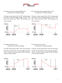
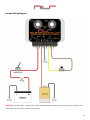
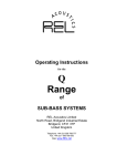
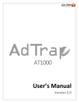
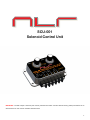
SCU-001
Solenoid Control Unit
IMPORTANT—the SOL+ output is internally over current protected and “MAY” turn OFF without warning. Always test before use to determine that an over current condi on does NOT exist! 1 Notice:
It is the responsibility of the purchaser to follow all guidelines and safety procedures supplied
with this product and any other manufactures product used with the SCU-001. It is also the
responsibility of the purchaser to determine compatibility of the SCU-001 with the vehicle and other
components.
NLR, LLC assumes no responsibility for damages resulting from accident, improper
installation, misuse, abuse, improper operation, lack of reasonable care, or all previously stated
reasons due to incompatibility with other manufacturer’s products.
NLR, LLC assumes no responsibility or liability for damages incurred from the use of products
manufactured or sold by NLR, LLC on vehicles used for competition racing.
NLR, LLC neither recommends nor approves the use of products manufactured or sold by
Next Level Racing, Inc. on vehicles which may be driven on public highways or roads, and assumes
no responsibility for damages incurred from such use.
NLR, LLC does not recommend nor condone the use of its products for illegal street racing.
Installation of NLR, LLC products signifies that you have read this document and agree to the
terms stated within.
Important Information:
Follow all recommended safety guidelines from this and other manufactures installation
guides.
Static suppression ignition wires must be used with this unit! Mount the unit as far away from
secondary ignition components(coil, ignition wires, etc.) as physically possible.
2 Descrip on The SCU-001 controller provides an adjustable frequency, duty cycle, and ramp me to control air, nitrous/co2 and/or fluid flow/pressure (hydraulics). The adjustable features of this unit make it very unique as it provides a mul programmable pla orm for controlling a solenoid to serve whatever purpose you desire. Unlike ecu’s and solenoid controllers with limited capability the SCU-001 unit offers a mul dimensional capability not available anywhere else. The SCU-001 has several control configura ons to choose from. These are outlined in the following sec ons. The output provides +12V to operate the solenoid. This output is rated at 30 amps maximum. It should be taken into account that this ra ng is NOT for con nuous opera on. If the SCU-001 is driving a high amperage load it should be for short dura ons. The output is internally over current & over temperature protected. The various modes of opera on are selected by entering a “Programming” mode, se ng the dials to the desired mode of opera on and comple ng the programming cycle. The procedure to perform this is outlined in the following sec ons. The se ng dials can be adjusted at any me, however the “New” se ngs will only be applied when the “Start” input is ac vated and/or the controller is powered up. When the controller is programmed to one of the “Reset” modes the control ramp will be applied on power up and the ramp will repeat any me the “Start” input is ac vated. Please refer to Mode of Opera on Overview for more informa on. Table of Contents Mode of Opera on Overview Page 4, 5, 6 Determining Current Mode of Opera on Page 7 Programming Mode of Opera on Page 7 Frequency and Duty Cycle Charts Page 8 Example Setup and Opera on Page 9 Example Wiring Diagram Page 10 Warranty Page 11 3 Mode of Opera on Overview A—Variable Frequency (On to Off) 2—15Hz to 30Hz 3—27Hz to 42Hz On power up the output will be “On” and the ramp is used to par ally turn off the solenoid. In this mode Dial1 selects a star ng frequency and Dial2 selects a preset ramp. Turning the Dials up will make the ramp more aggressive. If one of the preset ramps does not work you will need to select a custom mode and configure as required. B—Variable Frequency (Off to On) 2—15Hz to 30Hz 3—27Hz to 42Hz On power up the output will be “Off” and the ramp is used to par ally turn on the solenoid. In this mode Dial1 selects a star ng frequency and Dial2 selects a preset ramp. Turning the Dials up will make the ramp more aggressive. If one of the preset ramps does not work you will need to select a custom mode and configure as required. All other modes of opera on use a common secondary configura on. 1—15Hz, .10 Second Base Time Period 2—15Hz, .25 Second Base Time Period 3—15Hz, .50 Second Base Time Period 4—15Hz, 1.0 Second Base Time Period 5—20Hz, .10 Second Base Time Period 6—20Hz, .25 Second Base Time Period 7—20Hz, .50 Second Base Time Period 8—20Hz, 1.0 Second Base Time Period 9—25Hz, .10 Second Base Time Period 10—25Hz, .25 Second Base Time Period 11—25Hz, .50 Second Base Time Period 12—25Hz, 1.0 Second Base Time Period 13—30Hz, .10 Second Base Time Period 14—30Hz, .25 Second Base Time Period 15—30Hz, .50 Second Base Time Period 16—30Hz, 1.0 Second Base Time Period The primary configura on se ng (A, B, C, etc…) determines the opera ng mode. This controls power on output state and the basic ramp func on. The secondary configura on sets the opera ng frequency and base me period. Both the primary and secondary configura on values can be programmed using a special sequence. When opera ng in mode C to J “Dial1” sets the target duty cycle percentage and “Dial2” sets the ramp me mul plier. The total ramp me is calculated using the “Base Time Period” mes the “Dial2” se ng. Example—.10 second base me period and Dial2 set on 5 = .5 second control ramp me. 4 C—Ramp Control Percentage Hold (Off to %) See Page 4 for secondary se ngs. On power up the output will be “Off” and the output will ramp to the percentage se ng on “Dial1”. The Base Time Period and “Dial2” will determine the ramp rate/ me. D—Ramp Control Percentage Hold (On to %) See Page 4 for secondary se ngs. On power up the output will be “On” and the output will ramp to the percentage se ng on “Dial1”. The Base Time Period and “Dial2” will determine the ramp rate/ me. E—Ramp Control (% to On) See Page 4 for secondary se ngs. On power up the output will be “Off” and the output will ramp to full On from the percentage se ng on “Dial1”. The Base Time Period and “Dial2” will determine the ramp rate/ me. F—Ramp Control (% to Off) See Page 4 for secondary se ngs. On power up the output will be “Off” and the output will ramp to full Off from the percentage se ng on “Dial1”. The Base Time Period and “Dial2” will determine the ramp rate/ me. 5 G—Ramp Control Percentage Hold (Off to %) (Reset) See Page 4 for secondary se ngs. On power up the output will automa cally apply the control ramp. When the “Start” input is ac vated the output will turn off and the control ramp will be reset. When the “Start” input is released the control ramp will run again. H—Ramp Control Percentage Hold (On to %) (Reset) See Page 4 for secondary se ngs. On power up the output will automa cally apply the control ramp. When the “Start” input is ac vated the output will turn off and the control ramp will be reset. When the “Start” input is released the control ramp will run again. I—Ramp Control (% to On) (Reset) See Page 4 for secondary se ngs. On power up the output will automa cally apply the control ramp. When the “Start” input is ac vated the output will turn off and the control ramp will be reset. When the “Start” input is released the control ramp will run again. J—Ramp Control (% to Off) (Reset) See Page 4 for secondary se ngs. On power up the output will automa cally apply the control ramp. When the “Start” input is ac vated the output will turn off and the control ramp will be reset. When the “Start” input is released the control ramp will run again. 6 Determining Current Mode of Opera on The programmed mode of opera on can be checked by se ng Dial1 to “B” and Dial2 to “2” and powering up the controller with the “Start” input ac vated. At this me the LED will blink green indica ng the current “Mode of Opera on” that is programmed into the controller. The LED will then blink red to indicate the “Range” if Mode A or Mode B is selected or “Base Time Period” for the control ramp in all other modes of opera on. By coun ng the number of mes the LED blinks the current se ng is determined. The controller will wait for the “Start” input to be released before con nuing with normal opera on. Programming Mode of Opera on The mode of opera on can be programmed by following the proper sequence. Please refer to “Mode of Opera on Overview” to determine the desired se ngs. Step 1—With the controller OFF set Dial1 to “A” and Dial2 to “1”, ac vate the “Start” input, and then turn power “ON” the LED will blink Red to indicate start of programming sequence. Step 2—set Dial1 and Dial2 to the desired se ngs. Step 3—release and re-ac vate the “Start” input. Step 4—If the programming sequence is successful the LED will blink Green. If the LED is blinking Red/Green an error occurred during the programming process and the sequence must be started again. Trying to enter a combina on of switch se ngs that is not supported will force an error. Step 5—Restart the controller with the “Start” input released (OFF). Important—if Dial1 and Dial2 are set to check mode of opera on or to enter programming the “Start” input should NOT be ac vated on power up if normal opera on is desired. With ALL other se ngs the “Start” input can be ac vated on power up if desired. 7 Frequency and Duty Cycle Charts Modes A & B with secondary se ng 2 (15Hz to 30Hz) Modes A & B with secondary se ng 3 (27Hz to 42Hz) Dial1 = Start Frequency Dial2 = Start and End duty cycle % Dial1 = Start Frequency Dial2 = Start and End duty cycle % A—30hZ B—29hZ C—28hZ D—27hZ E—26hZ F—25hZ G—24hZ H—23hZ I—22hZ J—21hZ K—20hZ L—19hZ M—18hZ N—17hZ O—16hZ P—15hZ 1—95% to 90%, slow ramp 2—95% to 88%, slow ramp 3—95% to 86%, slow ramp 4—94% to 82%, mild ramp 5—94% to 80%, mild ramp 6—94% to 78%, mild ramp 7—93% to 76%, fast ramp 8—93% to 74%, fast ramp 9—93% to 72%, fast ramp 10—92% to 70%, aggressive ramp 11—92% to 68%, aggressive ramp 12—92% to 66%, aggressive ramp 13—90% to 64%, aggressive ramp 14—88% to 62%, aggressive ramp 15—86% to 60%, aggressive ramp 16—85% to 50%, aggressive ramp A—42hZ B—41hZ C—40hZ D—39hZ E—38hZ F—37hZ G—36hZ H—35hZ I—34hZ J—33hZ K—32hZ L—31hZ M—30hZ N—29hZ O—28hZ P—27hZ 1—5% to 10%, slow ramp 2—5% to 12%, slow ramp 3—5% to 14%, slow ramp 4—6% to 18%, mild ramp 5—6% to 20%, mild ramp 6—6% to 22%, mild ramp 7—7% to 24%, fast ramp 8—7% to 26%, fast ramp 9—7% to 28%, fast ramp 10—8% to 30%, aggressive ramp 11—8% to 32%, aggressive ramp 12—8% to 34%, aggressive ramp 13—10% to 36%, aggressive ramp 14—12% to 38%, aggressive ramp 15—14% to 40%, aggressive ramp 16—15% to 50%, aggressive ramp In all other modes Dial1 determines the Start or End duty cycle percentage depending on current mode of opera on. Dial2 is the mul plier for the ramp control me. Please refer to “Mode of Opera on Overview” and “Example Setup and Opera on” for more informa on. Dial 1 A—25% B—30% C—35% D—40% E—45% F—50% G—55% H—60% I—65% J—70% K—75% L—80% M—85% N—90% O—95% P—100% Dial 2 1—Base Time mul plied by 1 2—Base Time mul plied by 2 3—Base Time mul plied by 3 4—Base Time mul plied by 4 5—Base Time mul plied by 5 6—Base Time mul plied by 6 7—Base Time mul plied by 7 8—Base Time mul plied by 8 9—Base Time mul plied by 9 10—Base Time mul plied by 10 11—Base Time mul plied by 11 12—Base Time mul plied by 12 13—Base Time mul plied by 13 14—Base Time mul plied by 14 15—Base Time mul plied by 15 16—Base Time mul plied by 16 8 Example Setup and Opera on This example is using Mode of Opera on “C”, secondary Base Time se ng of “1”, Dial1 set at 50%, and Dial2 set at “5”. The control ramp will start at 0% or OFF and ramp up to a 50% duty cycle over .5 seconds. The ramp me is determined by the programmed secondary se ng (see page 4) which in this case is .1 second, this base me se ng is mul plied by the Dial2 se ng “5” which equals .5 second total ramp me. Ramp Time = Base Time Period * Dial2 Se ng = .1 second * 5 = .5 second 9 Example Wiring Diagram IMPORTANT—the SOL+ output is internally over current protected and MAY turn OFF without warning. Always test before use to determine that an over current condi on does NOT exist! 10 Warranty
NLR, LLC warrants to the original purchaser that the SCU-001 controller shall be free from
defects in parts and workmanship under normal use for 6 months from the date of purchase.
NLR, LLC obligation under this warranty is limited to the repair or replacement of any
component found to be defective when returned postpaid to NLR, LLC.
The controller must be returned with evidence of place and date of purchase or warranty will
be void. The warranty will not apply if the SCU-001 controller has been installed incorrectly,
repaired, damaged, or tampered with by misuse, negligence or accident.
11