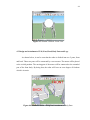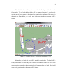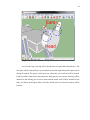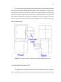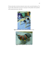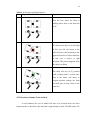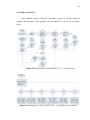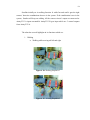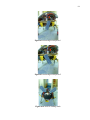
1
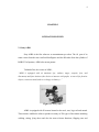
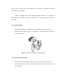
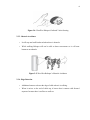
PSZ 19:16 (Pind. 1/07) UNIVERSITI TEKNOLOGI MALAYSIA DECLARATION OF THESIS / UNDERGRADUATE PROJECT PAPER AND COPYRIGHT Author’s full name : Date of birth : Title : MOHAMAD FADZLI BIN HANIFF 25 SEPTEMBER 1987 SENSBOT : 4 LEGGED AUTONOMOUS ROBOT Academic Session: 2010/2011 I declare that this thesis is classified as : √ CONFIDENTIAL (Contains confidential information under the Official Secret Act 1972)* RESTRICTED (Contains restricted information as specified by the organisation where research was done)* OPEN ACCESS I agree that my thesis to be published as online open access (full text) I acknowledged that Universiti Teknologi Malaysia reserves the right as follows : 1. The thesis is the property of Universiti Teknologi Malaysia. 2. The Library of Universiti Teknologi Malaysia has the right to make copies for the purpose of research only. 3. The Library has the right to make copies of the thesis for academic exchange. Certified by : SIGNATURE 870925-56-5791 (NEW IC NO. /PASSPORT NO.) Date : NOTES : SIGNATURE OF SUPERVISOR PROF. DR. SHAMSUDIN HJ. MOHD AMIN NAME OF SUPERVISOR Date : * If the thesis is CONFIDENTIAL or RESTRICTED, please attach with the letter from the organisation with period and reasons for confidentiality or restriction. “I hereby declared that I have read the content of this thesis and in my opinion it is suitable in terms of scope and quality for the award of the degree of Bachelor of Engineering (Electrical – Mechatronic).” Signature : ________________________________________ Name : PROF. DR. SHAMSUDIN HJ. MOHD AMIN Date : 2 MAY 2011 SENSBOT: 4 LEGGED AUTONOMOUS ROBOT MOHAMAD FADZLI BIN HANIFF Project Report Submitted as Partial Fulfillment of the requirement for the award of the Bachelor Degree of Electrical Engineering (Mechatronics) FACULTY OF ELECTRICAL ENGINEERING UNIVERSITI TEKNOLOGI MALAYSIA MAY 2011 i DECLARATION “I hereby declared that this thesis entitled SensBot is a result of my own research and idea, except for works that have been cited clearly in the references”. Signature : __________________________________ Name : MOHAMAD FADZLI BIN HANIFF Date : 12 MAY 2008 ii ACKNOWLEDGEMENT So many people have played so many roles in doing this project until it is done, from only imagination to reality. They helped in various aspects and contributed in figuring out what to do in materializing this project from the scratch. All their supports no matter mental, physical or emotional supports helped me a lot in making sure the project can be run smoothly. I wish to grab this opportunity to express my appreciation to my FYP supervisor, PROF. DR. SHAMSUDIN HJ. MOHD AMIN for guiding and advising me for two semesters. Even though it is hard for him to spend time for me and fellow students under his supervision, he still tried to help. Special extra thanks to ASSOC. PROF. DR MOHAMAD NOH AHMAD, DR. DR ABDUL RASHID HUSAIN for giving me some advice and encouragement during the project development. A huge appreciation is dedicated to FKE’s Robotic Lab’s technician, En Noh b Mohamad for helping me during my experiments, troubleshooting and even in robot’s development stage, always been there to make sure my work can be done successfully. My fellow friends especially Nur Liyana Binti Mohd Suyut, Muhammad Akmal Bin Mohamad Roslan and Muhammad Asyraf Bin Azman and many more for helping me during my hard time by sharing knowledge, sharing expertise and giving encouragement. Without their helps, I might not be writing this thesis while smiling. Lastly, I am grateful to have a family that understands me for not going back home during holidays because of the project. iii ABSTRACT 4 legged robot is a very common thing in engineering today. It even catches the attention of university students, where there are so many final year projects that are using this robot as the topic. As we all know, robot are used for entertainment from toy companies to films. It is very common to see robot in commercials on television. This project deals with the development of autonomous 4 legged robot. Autonomous means the robot can adapt to the environment without being controlled by human or user. There is no remote control needed in this project. This project’s idea occurs from the inspirations caused by Sony AIBO and WowWee Robopet. The objective of this project is to build an autonomous 4 legged robot that can detect the movement of object in front of it, SensBot. SensBot will be programmed to do movements such as walking, wiggle tail, barge to the front, and wiggle without the aids of human. The robot will be able to react differently to moving and non moving object. Lastly, SensBot will be the ability to use its waist in obstacle avoiding movement sequence. iv ABSTRAK Robot berkaki empat adalah sangat umum dalam bidang kejuruteraan masa kini. Ia juga menarik minat mahasiswa-mahasiswa universiti dimana terdapat banyak projek tahun akhir yang menggunakan robot ini sebagai topik. Seperti yang kita tahu, robot digunakan untuk hiburan, dari permainan hingga filem. Ia adalah sangan biasa untuk melihat robot di dalam iklan di televisyen. Projek ini berkaitan dengan pembuatan robot automasi berkaki empat. Automasi bermaksud robot itu mampu menyesuaikan diri dengan persekitaran tanpa dikawal oleh manusia. Tiada panel kawalan di dalam projek ini. Idea untuk menjalankan projek ini adalah timbul dari inspirasi yang disebabkan oleh Sony AIBO dan WowWee Robopet. Objektif projek ini adalah untuk membina robot automasi berkaki empat yang boleh mengesan pergerakan object yang berada di depannnya, SensBot. SensBot akan deprogram untuk melakukan pergerakan seperti berjalan, menggoyangkan ekor dan menggoyangkan ekor tanpa pertolongan dari manusia. Robot ini akan mampu member rekasi yang berbeza kepada objek bergerak dan object tidak bergerak. Akhir sekali, SensBot akan mempunyai kebolehan menggunakan pinggangnya dalam urutan pergerakan mengelak objek. v TABLE OF CONTENTS CHAPTER TITLE PAGE DECLARATION i ACKNOWLEDGEMENT ii ABSTRACT iii ABSTRAK iv TABLE OF CONTENTS v LIST OF TABLES viii LIST OF FIGURES ix LIST OF ABBREVIATIONS xii LIST OF APPENDIX xiii CHAPTER 1 1.1 The Development Of Animal Robots 1 INTRODUCTION 1.2 Objectives 2 1.3 Scope Of Project 2 1.4 Summary Of Works 3 1.5 Outline Of Thesis 4 CHAPTER 2 2.1 Sony AIBO 5 LITERATURE 2.2 WowWee Robopet 6 REVIEW 2.2.1. Sound Sensing 7 2.2.2. Infrared Vision Sensing 7 2.2.3. Obstacle Avoidance 8 2.2.4. Edge Detection 8 2.3 I-Dog 9 vi 2.4 Summary Of Literature Review 10 2.5 Problem Statements 10 CHAPTER 3 3.1 Component Selections 12 METHODOLOGY 3.2 SN-IRS-02 - IR Sensor Set With Socket 12 OF COMPONENTS 3.3 SN-GP2Y0A21 - Analog Distance Sensor 13 CHOSEN 3.4 PIR Sensor(Passive Infrared Sensor) 15 3.5 RC Servo C36R 16 3.6 RC Micro Servo Motor 17 3.7 Comparator LM358 18 3.8 ATMEL ATTINY2313 19 CHAPTER 4 4.1 Sketch 21 MECHANICAL 4.2 Design and Attachment of Tail, Ears, Head, 23 DESIGN Body Parts and Legs 4.3 Detail Drawing on Dimensions of Robot 27 Mechanical Parts 4.4 Actual SensBot Mechanical Parts 27 4.5 Movement Design 30 4.5.1 Obstacles Avoiding 30 4.5.2 Reaction to Human Touch on Head 31 4.5.3 Reaction to Moving and Non-Moving 33 Object CHAPTER 5 5.1 Schematic 34 CIRCUITS 5.1 .1Circuit For IR Sensors 34 DESIGN 5.1.2 Circuit For Front Detection 35 5.1.3 Circuit For Attiny2313 36 5.1.4 Circuit For ISP cable 38 5.2 Actual Circuits 38 vii 5.2.1 Circuits For Sensors’ Location 38 5.2.2 Attiny2313 Circuit’s Location 40 5.2.3 Connection between Attiny2313 and 41 PC using ISP cable 5.3 Software For Programming Attiny2313 42 CHAPTER 6 6.1 Distance Of IR Sensors Detection 43 RESULTS OF 6.2 Output Voltage of Analog Distance Sensor 44 EXPERIMENTS 6.3 PIR Sensor’s Reaction 45 6.4 Combining Analog Distance Sensor And PIR To 46 Detect Movement At Certain Distance And Giving Time To PIR To Calibrate To Environment 6.5 Servo Motor’s Response 48 6.6 SensBot’s System Flow 50 CHAPTER 7 7.1 Conclusions 57 CONCLUSION 7.2 Future Works 58 REFERENCES 59 AND FUTURE WORKS APPENDIX Appendix A – Program For Attiny2313 A 60 Appendix B – Program For Attiny2313 B 66 viii LIST OF TABLES Table 1.1: First semester Gantt Chart Table 1.2: Second Semester Gantt Chart Table 4.1: Obstacle Avoiding Sequence Table 4.2: Reaction To Touch On Head Table 4.3: Reaction to Moving and Non-Moving Object Table 5.1: Functions of Attiny2313 circuits ix LIST OF FIGURES Figure 2.1: Sony AIBO Figure 2.2: WowWee Robopet Figure 2.3: WowWee Robopet’s Sound Sensing Figure 2.4: WowWee Robopet’s Infrared Vision Sensing Figure 2.5: WowWee Robopet’s Obstacle Avoidance Figure 2.6: WowWee Robopet’s Edge Detection Figure 2.7: I-Dog Figure 3.1: Effect of no socket on IR Figure 3.2: Emitting Infrared Pulse With Socket Figure 3.3: Detecting Infrared Pulse With Socket Figure 3.4: Analog Distance Sensor Figure 3.5: Characteristic Of Analog Distance Sensor Output(Output voltage versus distance Figure 3.6: PIR Sensor Figure 3.7: Frensel Lense Figure 3.8: RC Servo Figure 3.9: The Effect of PWM on RC Servo Figure 3.10: RC Micro Servo Figure 3.11: LM358 Architecture Figure 3.12: Attiny2313 Architecture Figure 4.1: Sensbot’s Sketch - Full View Figure 4.2: Sensbot’s Sketch - Side View x Figure 4.3: Sensbot’s Sketch - Back View Figure 4.4: Sensbot’s Sketch - Top View Figure 4.5: Sensbot’s Sketch - Front View Figure 4.6: Sensbot’s Sketch - Design and Attachment of Body Parts Figure 4.7: Sensbot’s Sketch - Design and Attachment of Tail Figure 4.8: Sensbot’s Sketch - Design and Attachment of Ears and Head Figure 4.9: Sensbot’s Sketch - Design and Attachment of Legs Figure 4.10: Sensbot’s Sketch - Dimensions for Ears, Legs and Tail Figure 4.11: Sensbot’s Sketch - Dimensions for front and back body parts Figure 4.12: SensBot’s Basic robot body without circuits Figure 4.13: Completed SensBot’s Full view Figure 4.14: SensBot’s Top View Figure 4.15: SensBot’s Leg Figure 4.16: SensBot’s Tail Figure 4.17: SensBot’s Ears and Head Figure 5.1: Circuit for 4 IR Sensors Figure 5.2: Circuit For Front Detection Figure 5.3: Attiny2313 Circuit Pins Locations Figure 5.4: Circuit Attiny2313 Figure 5.5: ISP cable circuit connection. Figure 5.6: Circuits For Sensors’ Location Figure 5.7: IR sensors’ locations Figure 5.8: PIR and Analog Distance Sensors Location Figure 5.9: Attiny2313 Circuit Figure 5.10: Position of Attiny2313 Circuit on Sensbot. Figure 5.11: Full Circuit view of SensBot Figure 5.12: Connection between Attiny2313 and PC using ICP cable Figure 5.13: Bascom AVR Figure 6.1: Maximum Distance Of IR Detection Versus Input Supply Figure 6.2: Output Voltage Vs Distance Of Detection Figure 6.3: PIR response, Output Versus Distance xi Figure 6.4: PIR Response: Output Versus Time Figure 6.5: Combining PIR and Analog Distance Sensor Figure 6.6: PIR and Analog Distance Detecting Moving Object In Closer Distance Figure 6.7: Servo Motor’s Response Figure 6.8: Program Flow Chart ATTINY2313 A – Controls 4 Legs Figure 6.9: Program Flow Chart ATTINY2313 B – Controls Ears, waist and tail Figure 6.10: Walking Sequence 1 Figure 6.11: Walking Sequence 2 Figure 6.12: Moving tail Sequence 1 Figure 6.13: Moving tail Sequence 2 Figure 6.14: Ears in walking mode Figure 6.15: Standing/Stop position Figure 6.16: Ears in Standing/Stop position Figure 6.17: Moving Ears Sequence 1 Figure 6.18: Moving Ears Sequence 2 Figure 6.19: Ears up for moving object Figure 6.20: Ears lower for non moving object Figure 6.21: Turn left when object at right Figure 6.22: Turn right when object at left xii LIST OF ABBREVIATIONS IR - Infra Red PIR - Passive Infra Red PC - Personal Computer PWM - Pulse Width Modulation ISP - In System Programmer LPT - Line Print Terminal xiii LIST OF APPENDIX Appendix A – Program For Attiny2313 A Appendix B – Program For Attiny2313 B 1 CHAPTER 1 INTRODUCTION 1.1 The Development Of Animal Robots Nowadays, there are so many robots created resembling the characteristic of animal such as dog, cat and even dinosaur. These robots are just the incomplete resembles of those real animal. Even though there are many robots created based on one animal, but each of the robots have its own functions and specialties. The functions are based on the reaction of the real animal in term of movements and also sound. These animal robots are used as pet, security guard, military purpose and also research purposes. As pet, these robot needs to be built as close as possible to the real animals in term of reactions. A pet must be able to react to its master in friendly way, it also should be able to differentiate between living things and non living things so that it can give specific reactions to each one. If not, the robot cannot be considered as a pet. These robots must be able to operate by its own or can operate automatically. Remote control is not necessary to control the movements or behaviors of the robots. These robots must be built to be intelligent to control its own reactions depending on the surrounding conditions. These reactions may be complex but it is necessary to improve the current animal robot. But it is not necessary to build all the reactions at the same 2 time because a detail study must be done on the real animal. Everything should be done one by one so that the reactions truly resembles the real ones. From day to day, these incomplete resembles of real animals are developed to be more advance, complex and detail so that it will become more closer in resembling the real animals. The developments of the animal resembling robots will always exist because there are some complex functions that are being left out from the past project. As long there are behaviors of real animal that can be implemented in robots, the development will keep on happening. 1.2 Objectives The objectives of this project are as below: 1. To build an animal robot or 4 legged robot that able differentiate between human and obstacles(non living things) and react differently to both. 2. To build a 4 legged robot that only have basic functions such as can produce sounds, walking, avoid obstacle, sitting, standing and moving its ears and tail. 3. To build a 4 legged robot that use a different way of obstacle avoidance sequence. 1.3 Scope Of Project The scope of project will give the brief image of the outcome of the project and also giving the direction of what has to be done to fulfill the objectives. The scopes are as stated below: 1. SensBot will be totally autonomous and microcontroller based with a small easy to carry size. 3 2. SenseBot will be a robot that resembles a dog. 3. SensBot will ONLY be able to perform the simple walking locomotion like a dog 4. SensBot will has several basic canine characteristic like producing sounds, obstacles avoidance, ducking and sitting down . 5. SensBot will be able to give different reactions to human and obstacles 6. SenseBot will resembles the stray dog and explore the environment by its own. 1.4 Summary Of Works The schedule of the tasks and works done for this project are illustrated in the form of Gantt charts in Table 1.1 and Table 1.2 below Weeks 01 02 03 04 05 Proposal Background Study Circuit Designing Part Purchasing Component Study Circuit Construction Mehcanical Design Report Writing Presentation Table 1.1: First semester Gantt Chart 06 07 08 09 10 11 12 13 14 15 4 Weeks 01 02 03 04 05 06 Program Flow Design Program Writing Testing Program Modification /Fine Tuning Demo Preparation Report Writing Presentation Thesis Compilation Table 1.2: Second Semester Gantt Chart 07 08 09 10 11 12 13 14 15 1.5 Outline Of Thesis The remaining contents of this thesis are organized as follow: Chapter 2: Theory and literature review that have been done for robot pets Chapter 3: Methodology for component selections Chapter 4: Mechanical design of the robot from the sketches, actuators, leg design, body design and head attachment. The movement design of the robot will also be discussed in this chapter. Chapter 5: Circuitry design and software development for main circuitry system, infra red, PIR and analog distance sensors and software used for programming purpose. Chapter 6: The experimental results and discussions Chapter 7: Discussion of conclusions, future works. 5 CHAPTER 2 LITERATURE REVIEW 2.1 Sony AIBO Sony AIBO is the first robot act as entertainment pet robot. The AI part of its name comes from the term Artificial Intelligence and the BO taken from the syllabus of ROBOT. In Japanese, AIBO also means partner. Toshitada Doi, the creator of AIBO, “AIBO is equipped with six emotions (joy, sadness, anger, surprise, fear, and discontent) and four instincts (the desire to interact with people, to search for favorite objects, to move around, and to re-charge its battery)…” Figure 2.1: Sony AIBO AIBO is equipped with 20 motors located at the neck, ears, legs, tail and mouth. These motors enables the robot to produce as many as 250 types of movement including walking, sitting, lying down and also the most relevant functions, flapping ears and 6 wagging tail. AIBO expresses its emotions with a wag of his tail or by changing the color and shape of his eyes or by his body movements. AIBO has several senses that allow AIBO to interact with people such as touch (on his head, chin and back), hearing (stereo microphones) and sight (a camera in his head) and balance. It also has an infrared distance sensor, an acceleration sensor, and a temperature sensor. These allow AIBO to adapt to its surroundings, to interact with people - and to grow and learn from both. The pressure sensors on AIBO’s body make it react exactly when it is touched by any object, living beings. Meanwhile in real situation, animal gives different reaction to living beings and non living objects and react right before any object touches it. This is the weakness of AIBO. 2.2 WowWee Robopet Figure 2.2: WowWee Robopet This robot is a naturally active robot that have personality and a mind of its own. It will automatically explore environment and perform actions and tricks as it wanders around. The behavior can be train using the training buttons on the remote controller. 7 There is also a motor on its waist adding the extra degree of freedom to do some movements such as rolling. AIBO is equipped with several sensing systems that allow it to explore its environment and respond to human approach. The sensing systems are like the following: 2.2.1. Sound Sensing • Detecting loud and sharp sound with sensor located at the front of its body. • When this robot hears a noise, it will stand up, walk forward or even able to perform some trick. Figure 2.3: WowWee Robopet’s Sound Sensing 2.2.2. Infrared Vision Sensing • Sensors located at the head that enable it to detect movement to either side. • It will either walk towards the movement present a paw to the side that it senses the movement. 8 Figure 2.4: WowWee Robopet’s Infrared Vision Sensing 2.2.3. Obstacle Avoidance • It will stop and walk backward when there is obstacle. • While walking Robopet will not be able to detect movement so it will treat human as an obstacle. Figure 2.5: WowWee Robopet’s Obstacle Avoidance 2.2.4. Edge Detection • Additional sensors to detect the edge of table when it is walking. • When it arrives to the end of table top, it knows that it cannot walk forward anymore because there is no floor to walk on. 9 Figure 2.6: WowWee Robopet’s Edge Detection This robot is able to detect the motion in front of it and also do obstacle avoidance. The problem is, it will not be able to detect the motion while walking, so it will treat moving living things in front of it as obstacle and will avoid it. In real situation, if there is living beings such as human or other animal in front, animal will look and stare. This is the main problem of Robopet. The waist motor of this robot enabling it to do unique movements but is not used during walking movement just like real animal does. 2.3 I-Dog This is the final year project of FKE, UTM student, Ng Hock Yuan, year 2008 inspired by AIBO and Robopet. I-Dog is able to perform the standing, sitting, running and walking actions other than obstacles avoidance This robot takes the characteristic from Robopet which is the degree of freedom on the waist so that it can perform some extra task such as rolling and doing peeing position. I-Dog also able to response to word recognition for voice commands.It also has voice synthesizing ability such as barking, talking, singing and making some puppy noise. 10 Figure 2.7: I-Dog The most unique part is how the developer of I-Dog improved the robot’s one degree of freedom legs. The robot’s legs only have one degree of freedom for each one, but the developer modified the legs so that each leg has one actuator and a passive springy joint. The spring will act to absorb impact shocks from complicated bending movements in the joints. With this, the movement of the robot will be smoother. 2.4 Summary Of Literature Review Nowadays, there are lots of similar and identical projects that can be found across the internet and reference books motivated by the autonomous 4 legged pet robot technology. So in this chapter, the important characteristics of autonomous 4 legged pet robots such as Sony Aibo, WooWee Robopet and I-Dog which is useful for the project title are discussed. 2.5 Problem Statements From the three robots stated in the Literature Reviews part, some problem statement had been developed such as: 11 1. The ability of Sony AIBO to react to human touch is helped by using pressure sensors but it cannot differentiate if the one that touches it is living beings or any non living things object that fell on it. 2. WowwWee Robopet and UTM’s I-Dog gives the same reaction to living things and obstacles because their inability to tell if its living beings or non living things. 3. In WowwWee Robopet and UTM’s I-Dog, the waist degree of freedom is only used to perform special task such as peeing position, and rolling but not during walking action. From the problem statement concluded from the literature reviews, a 4 legged autonomous robot with ability to sense movement, using its waist for moving and react differently to moving and non moving object named SensBot are built. 12 CHAPTER 3 METHODOLOGY OF COMPONENTS CHOSEN 3.1 Component Selections Many components are used for this project, 3 types of sensors, 2 types of servo motors, controller, and comparator. The descriptions of the component will be discussed in the next subtopics. 3.2 SN-IRS-02 - IR Sensor Set With Socket This component contains IR(Infrared) transmitter and an IR receiver mounted side by side. Both of the sub components are covered by a rectangular socket to minimize the influence from the environment This sensor can be used as a reflective type IR sensor for mobile robot It can detect the object up to 5cm distance, so it is good for close range detection such as reaction to human touch. 3 units of this type of sensor product will be used to 1. Detect the human touch on the head of the 4 legged robot 2. Detect the wall/object at its both sides. 13 Figure 3.1: Effect of no socket on IR Without Socket Wall Detector will keep on receiving the infrared pulse beam from the emitter because of both emitter and detector are located next to each other. Figure 3.2: Emitting Infrared Pulse With Socket Figure 3.3: Detecting Infrared Pulse With Socket With Socket By having the socket wall between emitter and detector, the detector wont Wall able to receive any pulse from infrared emitter from other direction except front. The wall blocks the pulse from to be detected by detector from side. 3.3 SN-GP2Y0A21 - Analog Distance Sensor This is a distance measuring sensor unit, using the integrated combination of PSD (position sensitive detector), IRED (infrared emitting diode) and signal processing 14 circuit. The environmental temperature and the operating duration are not influenced easily to the distance detection because of adopting the triangulation method. Figure 3.4: Analog Distance Sensor This sensor ‘s range of detection is from 10cm up to 80cm. The best thing about this device is the outputs where the output voltage corresponds to the detection distance. The closer the object detected, the higer the output voltage of this sensor. So this sensor can also be used as a proximity sensor. It is good to be used when a moving robot needs to react to blocking object before it become too close with the object such as other animal, human or wall. With the advantage stated before, the detection distance of the robot can be fixed by using potentiometer. Figure 3.5: Characteristic Of Analog Distance Sensor Output (Output voltage versus distance) 15 3.4 PIR Sensor(Passive Infrared Sensor) Figure 3.6: PIR Sensor This component is a pyroelectric device that detects motion by measuring changes in the infrared levels emitted by surrounding objects. This motion can be detected by checking for a high signal on a single I/O pin. The product features include: 1. Single bit output 2. Small size makes it easy to conceal 3. Compatible with all types of microcontrollers The sensor can sense the change in the amount of infrared energy within small distances, approximately up to 10 inches. For detecting movements at longer distance, infrared radiation has to be focused. This focusing is done by a Fresnel lens which focuses the infrared signals onto the elements made of a crystalline material that generates an electric charge when exposed to infrared radiation. The Fresnel lens condenses light, providing a larger range of IR to the sensor. With the lense, the PIR Sensor has a range of approximately 5 meters. 16 Figure 3.7: Frensel Lense 3.5 RC Servo C36R RC servos are become more popular in robotics, creating humanoid robot, biologically inspired robot, robotic arm and etc because its’ ability to rotate and maintain and certain location, position or angle according to control pulses from a single wire. Features: 1. Control position through Pulse Code Modulation 2. Pulse width range: ~ 0.5ms – 2.5ms 3. Come with servo horn and screw accessories 17 Figure 3.8: RC Servo The angle is determined by the duration of a pulse that is applied to the signal wire. This is called Pulse Width Modulation. So the motor can be connected directly from the processor. The position pulse must be repeated to instruct the servo to stay in that position. The same pulses must be provided along the time during the position or else the position will change Figure 3.9: The Effect of PWM on RC Servo 3.6 RC Micro Servo Motor This motor works just like the previous servo motor stated. The different is the size and power.The features of this motor are such as: 18 1. Micro size servo Speed (sec/60deg): 0.12/4.8V, 0.11/6.0V 2. Torque (Kg-cm): 1.50/4.8V, 1.60/6.0V 3. Size (mm): 22.8x11.8x20.6 Weight (g): 10 Figure 3.10: RC Micro Servo 3.7 Comparator LM358 LM358 is a Low Power Dual Operational Amplifiers that contain two independent, high gain, internally frequency compensated operational amplifier which were designed specifically to operate from a single power supply for over a wide range of voltage. The advantages of this component are like below: Two internally compensated op amps Eliminates need for dual supplies Allows direct sensing near GND and VOUT also goes to GND Compatible with all forms of logic Power drain suitable for battery operation Wide power supply range: — Single supply: 3V to 32V — or dual supplies: ±1.5V to ±16V Very low supply current drain (500 μA)—essentially independent of supply voltage 19 Low input offset voltage: 2 mV Differential input voltage range equal to the power supply voltage Large output voltage swing Figure 3.11: LM358 Architecture 3.8 ATMEL ATTINY2313 Recently Atmel controllers are widely used and the application of Atmel can be found all over the internet. This controller is selected for the project because of the PWM (Pulse Width Modulation) pins that it have. Controllers like PIC does not have such pins, programmers have to use delay on and delay off instruction, 4 lines of instructions just to sent the PWM value. With this controller, PWM can be set by one line of instruction only. PWM is important to control servo motors, this is the main reason why Atmel is suitable for this project. Figure 3.12: Attiny2313 Architecture 20 Characteristics of ATTINY2313 1. Data and Non-volatile Program and Data Memories 2K Bytes of In-System Self Programmable Flash Endurance 10,000 Write/Erase Cycles 128 Bytes In-System Programmable EEPROM Endurance: 100,000 Write/Erase Cycles 128 Bytes Internal SRAM Programming Lock for Flash Program and EEPROM Data Security 2. Peripheral Features One 8-bit Timer/Counter with Separate Prescaler and Compare Mode One 16-bit Timer/Counter with Separate Prescaler, Compare and Capture Modes Four PWM Channels 3. I/O and Packages 18 Programmable I/O Lines 20-pin PDIP, 20-pin SOIC, 20-pad QFN/MLF 4. Operating Voltages • 1.8 – 5.5V (ATtiny2313V) 5.5V (ATtiny2313) 21 CHAPTER 4 MECHANICAL DESIGN 4.1 Sketch The sketch of the robot had been done by using Google Sketch Software. Below are several views of the robot sketch Figure 4.1: Sensbot’s Sketch - Full View 22 Figure 4.2: Sensbot’s Sketch - Side View Figure 4.3: Sensbot’s Sketch - Back View Figure 4.4: Sensbot’s Sketch - Top View 23 Figure 4.5: Sensbot’s Sketch - Front View 4.2 Design and Attachment of Tail, Ears, Head, Body Parts and Legs As shown below, it can be seen that the robot is divided into two 2 parts, front and back. These two parts will be connected by a servo motor. The motor will be placed at the circled position. The moving part of the motor will be connected to the extended part of the front body. By doing that, the robot will have an extra degree of freedom which is its waist. Figure 4.6: Sensbot’s Sketch - Design and Attachment of Body Parts 24 The tail of the robot will be positioned at the back of back part of the robot as the figure below. The tail and the back body will be connected together by attaching the moving part of a servo motor to the tail and the motor itself to back part of the robot. As shown in the figure below, the circled area is the area that the servo motor will be located. Figure 4.7: Sensbot’s Sketch - Design and Attachment of Tail Meanwhile, the head and ears will be attached to each other. The head will be fixedly attached to the front body. The ears will be connected to the two micro servo motors moving part while the motors itself will be attached to the head. The circled areas are the position where the motors will be located. 25 Figure 4.8: Sensbot’s Sketch - Design and Attachment of Ears and Head As in for the legs, each leg will be divided into two parts like shown below. The two parts will be connected by a screw and nut so that the angle between the parts can be change if needed. The green circled areas are where the screw and nut will be located. Each leg will be connected to the prospective body part by servo motor. Each leg will be attached to the moving part of servo motor and the motor itself will be attached to the body. As shown in the figure below, the blue circled areas are where the motors will be located. 26 Figure 4.9: Sensbot’s Sketch - Design and Attachment of Legs 4.3 Detail Drawing on Dimensions of Robot Mechanical Parts Below is the drawing that indicated the dimensions of legs, tails and ears. Since each legs are divided into two, so there are 8 parts just for the legs. The dimensions of the legs will be the same just like the tail. The dimensions are in inches. Figure 4.10: Sensbot’s Sketch - Dimensions for Ears, Legs and Tail 27 As in for the body parts, the figure below shows that the design had been change from using semi-round extended parts into simple square extended parts. Also, now the moving part of the motor waist will be attached to the back extended part of back body part. The head of the robot will be attached at the extended part of the front body. The parts without extended part are used to be the platform of the circuitry part. The circuits will be combined together on the platforms and the platform will be attached on the parts that have extended part. Figure 4.11: Sensbot’s Sketch - Dimensions for front and back body parts 4.4 Actual SensBot Mechanical Parts The figures below shows the actual robot after the attachments is done. The legs, tail, ears, and body are covered by jeans to cover the circuits and to make it look tidy. 28 The basic robot body is the robot without the circuits, head, ears and tail attachment. The circuits will be attached first on two pieces of prospect used as platform and the platform will be attached on the basic robot body. Figure 4.12: SensBot’s Basic robot body without circuits Figure 4.13: Completed SensBot’s Full view 29 Figure 4.14: SensBot’s Top View Figure 4.15: SensBot’s Leg Figure 4.16: SensBot’s Tail 30 Figure 4.17: SensBot’s Ears and Head 4.5 Movement Design There are 3 other functions designed other than walking, which are obstacle avoiding, reaction to touch on head and reaction to moving and non moving object. The explanations of each will be discussed in sub topics. 4.5.1 Obstacles Avoiding Using the motor on the waist to “curves” the body of robot to turn left or right. Inspired by Robopet, instead of using the waist to make twisting movement, the degree of freedom will be used for turning right and left sequence. The sequence will be explained below by considering the robot detects wall on its left side. 31 Table 4.1: Obstacle Avoiding Sequence State Top and Side View Explaination 1. This the state where the robot is walking where there is not detection at all 2. If it detects that object at its left/right in this case left, the motor at the waist will move the front body to the opposite direction of object detected, in this case, it moves to right direction. This process happens while the robot is walking. 3. The robot will stay in [2] position while walking until a certain time, then it the motor will return to original position making the front and back part of body return to the same line. 4.5.2 Reaction to Human Touch on Head In real situation, the ears of animal will start to be lowered down not when human touches its head but when the hand is approaching its head. The PIR sensor will 32 help the robot to differentiate between non living objects and living beings. If it is just a ceiling or non living object it will duck. Table 4.2: Reaction To Touch On Head State Image from Side View Explaination 1. At certain distance the IR sensors cannot detect the human hand. So the ears will stay like it was. Meanwhile, the tail moves left and right while the robot is walking. 2. When the IR sensor on the head detects the hand, the robot will stop walking and the ears will turn up and down several times, same goes for the tail. Both moves at higher speed than the tail’s speed before detecting object on the head. 33 4.5.3 Reaction to Moving and Non-Moving Object The reaction to the moving and non moving object will be explained in the table below. Table 4.3: Reaction to Moving and Non-Moving Object State Top and Side View Explaination 1. When robot detects object at the front, the robot will stop and wait for a moment to detect if it is moving object or non-moving object. 2. If it is a non-moving object, the robot will turn down it ears and moves it tails left and right several times. Then if the robot still detects object in front of it, it will repeat [1]. If there is no object, the robot will continue walking. 3. If it is a moving object the robot will change it body posture and move its ears upward. The tail will remain stop. Then if the robot still detects object in front of it, it will repeat [1]. If there is no object, the robot will continue walking. 34 CHAPTER 5 CIRCUITS DESIGN 5.1 Schematic 5.1.1 Circuit For IR Sensors Four IR sensors will be used on this robot. Each of this IR will be located at different location: HEAD, BACK OF BODY, LEFT OF BODY and RIGHT OF BODY Figure 5.1: Circuit for 4 IR Sensors 35 The outputs of the comparator LM358 will be connected to controller directly to be used as input signal. These inputs will determine how the robot will react. 5.1.2 Circuit For Front Detection In this circuit, PIR and Analog distance sensors are used to detect if the object in front of the robot head is living thins or not. The output of the comparator will be connected to microcontroller. The output voltage of comparator is 5V, that is why it can be connected directly to the controller. Figure 5.2: Circuit For Front Detection 5.1.3 Circuit For Attiny2313 This circuit is used in Problem Based Laboratory program in Fakulti Kejuruteraan Elektrik for final year students. The designer of this circuit is Dr Rosbi Mamat, the faculty’s lecturer. This circuit is designed so that it can be directly programmed using BASCOM AVR IDE. Two sets of this circuit will be used to control 8 servo motors; first circuit will send control outputs to second circuit as control inputs. Two sets is used because of 36 there is only 4 PWM pins on Attiny2313, other commercialized Atmel controllers have up to only 6 PWM pins or a bit costly. The simple solution is to use two sets of 4 PWM pins. Figure 5.3: Attiny2313 Circuit Pins Locations 37 Figure 5.4: Circuit Attiny2313 38 5.1.4 Circuit For ISP cable The Attiny2313 circuit must be connected to PC using ISP cable and DB25 Male Printer Port Connector. Usually this connection only can be used on desktop, because notebook and laptop nowadays do not have the LPT. The ISP schematic is like below. Figure 5.5: ISP cable circuit connection. 5.2 Actual Circuits 5.2.1 Circuits For Sensors’ Location As shown below in the figure, the PIR, analog distance sensor and IR sensors circuits are combined on one board. The red rectangle area is PIR and analog distance sensor area meanwhile the blue rectangle is the area for the IR sensors circuit. Figure 5.6: Circuits For Sensors’ Location 39 Meanwhile the allocations of the sensors are shown in figures below. The IR sensors are located at the left, right and front sides of front body part. The IR at the front side is attached to the head. Figure 5.7: IR sensors’ locations For the PIR sensor and analog distance sensors, both are located at the head of SensBot just like in the figure below. The analog distance sensor is located on the face of SensBot meanwhile the PIR is located at the bottom part of the head. Figure 5.8: PIR and Analog Distance Sensors Location 40 5.2.2 Attiny2313 Circuit’s Location Meanwhile figures below shows the Attiny2313 circuit. The size of the Attniy2313 circuit is 3x3 inch squares Figure 5.9: Attiny2313 Circuit Figure below shows the location of the two Attiny2313 circuits on the Sensbot. The circuits are located at the back part of the robot body next to each other. Each circuits will handle different inputs and outputs. Both circuits operate at frequency 1MHz and the PWM frequency is 50Hz since servo motors operate at that frequency rate. The functions of the two Attiny2313 circuits are listed in the table below. Figure 5.10: Position of Attiny2313 Circuit on Sensbot. 41 Attiny2313 Circuit Functions A Receives 5 sensors circuits output as its input and process it to control the 4 legs servo motors.This Atmel’s circuit also sends 3 control outputs to control Attiny2313 circuit B. B Receives 3 control output from circuit A as input and process it to control 4 motors for tail, ears and waist. Table 5.1: Functions of Attiny2313 circuits Figure below shows the attachment of all circuit to the robot body. The circuits are attached first to two plates of prospect and the attached to the basic robot body. Figure 5.11: Full Circuit view of SensBot 5.2.3 Connection between Attiny2313 and PC using ISP cable Figure below shows the connection between Attiny2313 circuit and PC using the ISP cable. Connection also can be made to notebook or laptop, but not all of it have the ISP port. The circuit does not have to be supplied with any supply voltage since the PC will supply the voltage trough ISP cable. Advantages of using this method is, the 42 program can be directly written into Attiny2313 with the same software used to write the program unlike PIC that have to use different software to write the program and to program the chip. Figure 5.12: Connection between Attiny2313 and PC using ISP cable 5.3 Software For Programming Attiny2313 BASCOM AVR IDE is used to program the Attiny2313 for this project. This software is very simple software and it can directly write program into the Attiny2313 without having to use another software just like PIC does. The programming is using C language, which is very familiar in engineering field. Figure 5.13: Bascom AVR 43 CHAPTER 6 RESULTS OF EXPERIMENTS 6.1 Distance Of IR Sensors Detection When voltage supply of 5V was used for the sensors circuit, it is found that the range of distance of detection of the sensors were very small, the range of detection can be observed by tuning the variable resistors on the circuits. Each sensors have its own variable resistor, the distance of detection can be varies by tuning the potentiometers. An experiment on the maximum detection of IR sensor’s circuit had been done. Instead of just using 5V voltage supply, it can be increased into up to 7V. It is found that the maximum distance of the IR sensors is affected by the input supply of the circuit. But too high supply voltage may ruin the sensors. Figure 6.1: Maximum Distance Of IR Detection Versus Input Supply 44 Since the robot needs to detect wall or object for left and right obstacle avoidance, it is better to use a high range detection but yet safe for the circuit. So supply input of 6V is chosen to operate the IR sensors’ circuit. The distance is not quite enough but this supply voltage value is safe enough and this range is enough for this project just to show the reaction of robot to the object at left or right. 6.2 Output Voltage of Analog Distance Sensor The distance sensor is the advance version IR sensor. It may have a great range of detection which is 80cm. But it is not necessary to use 80cm as the distance where the SensBot will detect object in front of it. For this project a smaller distance will be used so that during demo, SensBot wont be needing large space to operate at. The output become greater as the object getting closer, but the circuit is designed so that, comparator will produce high output when analog distance sensor detects object at certain distance and distance closer than that. This is done by using the potentiometers. A test had been done on the sensors at certain range or distance, to figure out the actual output response. 20cm is chosen as the distance where the object will be detected, so what was left is to find the output voltage the distance. This output voltage is needed as the inverting input of the comparator of sensors’ circuit will follows this value. 45 Figure 6.2: Output Voltage Vs Distance Of Detection 6.3 PIR Sensor’s Reaction An experiment had been done to observe the behavior of the PIR sensor. A problem is found after that. The output of the sensor will always be HIGH which is one fixed value no matter the distance of the moving object as can be seen in the figure below. The maximum distance it can detect movement from is 5m, and it can detect as wide as 120 degree angle area. This is because of the frensel lense as the casing of the sensor. Figure 6.3: PIR response, Output Versus Distance The another problem with PIR sensor is where it needs some time to calibrate itself with the environment condition before it can detect again. Meaning, the 46 surrounding area must be in stay during that calibration time, unless the sensor cannot function in a desired way. So SensBot need to give some time to the sensor so that it can calibrate itself to the environment condition. Figure 6.4: PIR Response: Output Versus Time 6.4 Combining Analog Distance Sensor And PIR To Detect Movement At Certain Distance And Giving Time To PIR To Calibrate To Environment The problem of PIR sensor, where output does not correspond to distance can be overcome by combining it with analog distance sensor. We do not want SensBot to detect object as far as 5m, it will become un-practical during the demo due to space problem. The problem can be solved by looking at the figure below. 47 Figure 6.5: Combining PIR and Analog Distance Sensor Firstly, the distance sensor will detect the object in front, then controller will read the input from PIR sensor. In other words, SensBot will detect object in front first, then it will ‘see’ if the object is moving object or not. The calibration time will be the delay time used before the controller process the PIR’s output. After distance sensor detected, SensBot will wait for several seconds to give time for PIR and then it will process PIR’s output. By doing this, the movement can be detected at close distance considering the object is the only thing in front of the robot. The response of PIR and analog distance sensor circuit when detecting a moving object can be seen in figure below. 48 Figure 6.6: PIR and Analog Distance Detecting Moving Object In Closer Distance 6.5 Servo Motor’s Response In SensBot, servo motors are used as the actuators for legs, ears, waist and tail.. The angle position of the moving part of servo motors can be determined with the value of pulse. But first, the full angle range of the servo motor need to be known. The actual pulse width modulation signal range also should be determined. 49 Figure 6.7: Servo Motor’s Response After some experiment, it is found that the full angle range of the motor is not 180 degree, but more than that, it is about 190-200 degree. This means, the actual pulse range is also bigger. This is not a problem for building SensBot. The problem is where the response of the motor where it is not linear, to be exact, the rate of increase of angle is not fixed. The motor suppose to be linear. When a linear increasing pulse is supplied to the motor, at first the motor will jump to higher angle than the calculated angle it should go to. The calculation is done by using the formula: ANGLEexpected = (PWMsupplied-PWMmin/(PWMmax-PWMmin))*180 It is found that the motor moves at higher rate at first, for angle less than 45 degree. For angle higher than 45 degree, the motor moves at lower rate which is follows the real rate even though the values of angle is different. 50 6.6 SensBot System Flow Since Sensbot contain 2 Attiny2313 controllers, each of it will have different program. The flowchart of the program for each Attiny2313 can be seen in figures below. Figure 6.8: Program Flow Chart ATTINY2313 A – Controls 4 Legs Figure 6.9: Program Flow Chart ATTINY2313 B – Controls Ears, waist and tail 51 SensBot initially set in walking function. It walks forward until it gets the right sensors’ detection combinations that are in the system. If the combination is not in the system, Sensbot will keep on walking. All the sensors circuits’ output are connected as Attiny2313 A inputs meanwhile Attiny2313 B gets input which are 3 control outputs from Attiny2313 A. The robot has several highlights in its functions which are: 1. Walking Walking while moving tail left and right. Figure 6.10: Walking Sequence 1 Figure 6.11: Walking Sequence 2 52 Figure 6.12: Moving tail Sequence 1 Figure 6.13: Moving tail Sequence 2 Figure 6.14: Ears in walking mode 53 2. Stop/Standing When there is detection on head and front, it will stop walking Figure 6.15: Standing/Stop position Figure 6.16: Ears in Standing/Stop position 3. Reaction to touch on head Moving ears and tail fast in specisifc standing position 54 Figure 6.17: Moving Ears Sequence 1 Figure 6.18: Moving Ears Sequence 2 4. Reaction to Moving objects Turn ears up and tail straight in specific standing position Figure 6.19: Ears up for moving object 55 5. Reaction to Non Moving objects Moves tail and turn ears down while in stop position Figure 6.20: Ears lower for non moving object 6. Left and Right Obstacle Avoidance Using Waist Waist will move to the side with no obstacle detection while walking. Figure 6.21: Turn left when object at right 56 Figure 6.22: Turn right when object at left 57 CHAPTER 7 CONCLUSION AND FUTURE WORKS 7.1 Conclusions This final year project able to archive the expected goals which are to design and to build an autonomous robot that can react differently to moving and non moving object. This project is inspired by the real animal behavior and is implemented using the controller, sensors, motors and other components as stated before. As the conclusion, SensBot, an autonomous robot that resembles a dog that have the features such as below are successfully completed • Walk • Stop when there is object in front • React differently to moving and non moving object • Move waist for Left and right obstacle avoidance • React to a touch on the top of its back by wiggling tail and ears This robot can fill the empty space in FYP idea of doing 4 legged where animal robot must react differently according to some important condition and in this case is the 58 object’s movement, also some of body part of waist are important to make me robot movement more realisitic. 7.2 Future Works 1. The robot could used more than one degree of freedom leg, so that the movement truly resembles the movement of walking animal. By using one degree leg, the robot’s movements are very stiff and the movement types are limited. 2. More flexible and efficient sensors other than PIR should be used to detect movements around the robot. The PIR seems to need some time to give reactions, real animal do takes time to figure out the environment but the PIR features that needs it to calibrate to the environment seems to take longer time. 3. Robot could be equipped with system than can produce sound according to the animal the robot resembles. Instead of just keep quiet, the robot may bark when there is moving object in front of it. If the three works above can be done, then the robot may resemble real animal reaction in terms or movements and sounds. 59 REFERENCES 1. AIBO - The No. 1 Selling Service Robot - Industrial Robot: An International Journal, Volume 28 . Number 1 .2001. pp. 24-26 2. Sony AIBO Robot Dog - http://www.robotbooks.com/sony_aibo.htm 3. WowwWee ROBOPET™, 2005 - User’s Manual 4. WowwWee ROBOPET™ http://www.wowwee.com/en/products/toys/robots/robotics/robocreatures/robopet 5. I-Dog - A Biological Inspired Quadruped Pet Robot - Ng Hock Yuan, Bachelor of Electrical Engineering (Mechatronics), 2008 6. Hildebrand M: Symmetrical gaits of dogs in relation to body build. - J Morphol 124:353, 1968. 7. Component Descriptions (IR, Analog Distance Sensor, PIR, Servo Motor, Micro Servo Motor) - http://cytron.com.my 8. ATTINY2313 Datasheet - http://www.atmel.com/ 9. PBL Manual - Dr. Rosbi bin Mamat 10. LM158/LM258/LM358/LM2904 Low Power Dual Operational Amplifiers National Semiconductor 60 APPENDIX Appendix A – Program For Attiny2313 A $regfile = "attiny2313.dat" $crystal = 1000000 Config Portd.0 = Output 'Control1 Config Portb.0 = Output 'Control2 Config Portb.1 = Output 'Control3 Config Portb.2 = Output 'OC0A Config Portb.3 = Output 'OC1A Config Portb.4 = Output 'OC1B Config Portd.5 = Output 'OC0B Config Pind.1 = Input Config Pind.2 = Input Config Pind.3 = Input Config Pind.4 = Input 61 Config Pinb.7 = Input Config Timer0 = Pwm , Compare A Pwm = Clear Down , Compare B Pwm = Clear Down , Prescale = 64 'timer 8 bit Config Timer1 = Pwm , Pwm = 8 , Compare A Pwm = Clear Down , Compare B Pwm = Clear Down , Prescale = 64 'timer 16 bit 'prescale 256 means the clock counts till 156.25 , f(pwm)=f(xtal)/(prescale*2*topcount) Frontleft Alias Portb.2 'OC0A Frontright Alias Portd.5 'OCOB Backleft Alias Portb.3 'OC1A Backright Alias Portb.4 'OC1B Control1 Alias Portd.0 Control2 Alias Portb.0 Control3 Alias Portb.1 Frontpir Alias Pind.1 Frontdistance Alias Pind.2 Leftir Alias Pind.3 Rightir Alias Pind.4 Headir Alias Pinb.7 Main: Do Frontpir = 0 Frontdistance = 0 Leftir = 0 Rightir = 0 Headir = 0 62 'No detection at all If Frontpir = 0 And Frontdistance = 0 And Leftir = 0 And Rightir = 0 And Headir = 0 Then 'Waist = original, Ears = down, Tail= left right Control1 = 0 Control2 = 0 Control3 = 0 'Walk normal Pwm0a = 11 Pwm0b = 11 Pwm1a = 7 Pwm1b = 7 Waitms 800 Pwm0a = 7 Pwm0b = 7 Pwm1a = 11 Pwm1b = 11 Waitms 800 'Touching the head Elseif Headir = 1 Then 'Waist = original, Ears = up down, Tail= left right Control1 = 0 Control2 = 0 Control3 = 1 'Lower body down Pwm0a = 11 Pwm0b = 7 Pwm1a = 11 Pwm1b = 7 63 Wait 2 'Detect object front Elseif Frontdistance = 1 And Leftir = 0 And Rightir = 0 And Headir = 0 Then 'Waist = original, Ears = down, Tail= stop Control1 = 0 Control2 = 1 Control3 = 0 'Stand Pwm0a = 7 Pwm0b = 11 Pwm1a = 11 Pwm1b = 7 Wait 3 'Moving object in front If Frontpir = 1 Then 'Waist = original, Ears = up, Tail= left right faster Control1 = 0 Control2 = 1 Control3 = 1 'Lower body down Pwm0a = 11 Pwm0b = 7 Pwm1a = 11 Pwm1b = 7 Wait 2 'No moving object Elseif Frontpir = 0 Then 'Waist = original, Ears = down, Tail= left right 64 Control1 = 0 Control2 = 0 Control3 = 0 'Stand Pwm0a = 7 Pwm0b = 11 Pwm1a = 11 Pwm1b = 7 Wait 2 End If 'Right side object detection Elseif Leftir = 0 And Rightir = 1 And Headir = 0 Then 'Waist = right, Ears = down, Tail= left right Control1 = 1 Control2 = 0 Control3 = 0 'Walk normal Pwm0a = 11 Pwm0b = 11 Pwm1a = 7 Pwm1b = 7 Waitms 800 Pwm0a = 7 Pwm0b = 7 Pwm1a = 11 Pwm1b = 11 Waitms 800 'Left side object detection Elseif Leftir = 1 And Rightir = 0 And Headir = 0 Then 65 'Waist = left, Ears = down, Tail= left right Control1 = 1 Control2 = 0 Control3 = 1 'Walk normal Pwm0a = 11 Pwm0b = 11 Pwm1a = 7 Pwm1b = 7 Waitms 800 Pwm0a = 7 Pwm0b = 7 Pwm1a = 11 Pwm1b = 11 Waitms 800 'Other than that, just walk Else 'Waist = original, Ears = down, Tail= left right Control1 = 0 Control2 = 0 Control3 = 0 'Walk normal Pwm0a = 11 Pwm0b = 11 Pwm1a = 7 Pwm1b = 7 Waitms 800 Pwm0a = 7 Pwm0b = 7 Pwm1a = 11 66 Pwm1b = 11 Waitms 800 End If Loop End Appendix B – Program For Attiny2313 B $regfile = "attiny2313.dat" $crystal = 1000000 Config Pind.0 = Input 'Control1 Config Pinb.0 = Input 'Control2 Config Pinb.1 = Input 'Control3 Config Portb.2 = Output 'OC0A Config Portb.3 = Output 'OC1A Config Portb.4 = Output 'OC1B Config Portd.5 = Output 'OC0B 67 Config Timer0 = Pwm , Compare A Pwm = Clear Down , Compare B Pwm = Clear Down , Prescale = 64 'timer 8 bit Config Timer1 = Pwm , Pwm = 8 , Compare A Pwm = Clear Down , Compare B Pwm = Clear Down , Prescale = 64 'timer 16 bit 'prescale 256 means the clock counts till 156.25 , f(pwm)=f(xtal)/(prescale*2*topcount) Ear1 Alias Portb.2 'OC0A Ear2 Alias Portd.5 'OCOB Waist Alias Portb.3 'OC1A Tail Alias Portb.4 'OC1B Control1 Alias Pind.0 Control2 Alias Pinb.0 Control3 Alias Pinb.1 Main: Do 'Waist = original, Ears = down, Tail= left right If Control1 = 0 And Control2 = 0 And Control3 = 0 Then Pwm0a = 15 Pwm0b = 4 Pwm1a = 7 Pwm1b = 5 Waitms 300 Pwm1b = 9 Waitms 300 68 'Waist = original, Ears = up down, Tail= left right Elseif Control1 = 0 And Control2 = 0 And Control3 = 1 Then Pwm0a = 15 Pwm0b = 4 Pwm1a = 7 Pwm1b = 5 Waitms 150 Pwm0a = 8 Pwm0b = 10 Pwm1b = 9 Waitms 150 'Waist = original, Ears = down, Tail= stop Elseif Control1 = 0 And Control2 = 1 And Control3 = 0 Then Pwm0a = 11 Pwm0b = 7 Pwm1a = 7 Pwm1b = 7 'Waist = original, Ears = up , Tail= left right faster Elseif Control1 = 0 And Control2 = 1 And Control3 = 1 Then Pwm0a = 7 Pwm0b = 11 Pwm1a = 7 Pwm1b = 5 Waitms 150 Pwm1b = 9 Waitms 150 69 'Waist = right, Ears = down, Tail= left right Elseif Control1 = 1 And Control2 = 0 And Control3 = 0 Then Pwm0a = 11 Pwm0b = 7 Pwm1a = 9 Pwm1b = 5 Waitms 300 Pwm1b = 9 Waitms 300 'Waist = left, Ears = down, Tail= left right Elseif Control1 = 1 And Control2 = 0 And Control3 = 1 Then Pwm0a = 11 Pwm0b = 7 Pwm1a = 5 Pwm1b = 5 Waitms 300 Pwm1b = 9 Waitms 300 End If Loop End