1
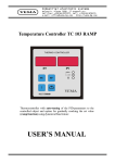
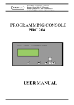
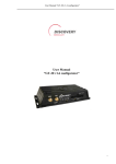
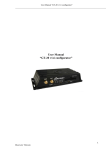
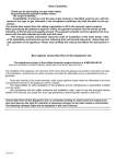
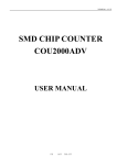
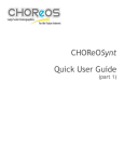
Industrial electronic systems
Bulgaria, Pleven 5800, 27 Osogovo str.
tel./fax: +359/64/870172, tel.: +359/64/870170
e-mail: [email protected]
http://vema-bg.com
VEMA
Two-channel programmable counter CN6S
VEMA
PROGRAMMABLE COUNTER
CN6S
OUT1
Esc
OUT2
USER'S MANUAL
I. Introduction.
The microprocessor programmable counters CN6S offer optimal comfort of service
and visualization of information.
The programmable counters CN6S are designed to work with all types of discrete
sensors for DC 10 to 30 voltage or mechanical switches.
The output signals are given either as a relay or a direct current output.
Each channel of the Counter can be set as a decrement or increment counter, length
meter, rpm meter, frequency meter or generator.
All parameters of the Counter can be set/changed in Program Mode. In this case, the
three symbol mnemonics of the parameters and the corresponding value (in three
digits or letters) are shown on the display. The set value (SV) of the Counter can also
be shown and changed using all six digits of the display.
Using the arrow buttons, the parameters' values can be changed by one unit or at a
faster rate (when the button is held pressed for a longer time). The values of the
parameters are automatically restricted within their possible limits.
II. Technical features.
1. Range of measure:
- counter or length meter
- frequency meter/generator
- rpm meter
2. Clock inputs ( I1, I2) switching frequency3. Reset inputs (R1, R2) 4. Indication (six digits)5. Control output:
- relay type- open collector type6.Inbuilt power source 7. Main supply8. Dimensions9.Ambient temperature-
0 to 999999;
0.00 to 5000.00 Hz ;
0.00 to 300000 min-1;
24V/10mA opto-isolated;
0 to 5000 ips/s;
24V/10mA opto-isolated;
seven-segment, height 14.2 mm
max. 250 V/2A, cosF=1
0/24V - 200 mA;
24V/100 mA;
100-242 V, 48-62 Hz;
48(H)х96(W)х100(D) mm;
0 to 50 °С.
2
III. Visualization and toggling of the channels.
CN6S is equipped with two independent channels. They can work as two independent
counters: ch1 with clock input I1 and reset input R1, and ch2 with clock input I2 and
reset input R2. It is also possible to bind the two channels into one counter ch1 with two
clock inputs I1 and I2, and one reset input R1. This assignment is controlled by the
parameter bnd in the left menu of ch1. After power-up the display of CN6S reads the
current measured value, and the user can check which of the channels is shown by
pressing and holding the 'Esc' button. The display will read either 'ch 1' or 'ch 2'
according to the selected channel. In order to switch to ch1, the user is to press and hold
the 'Esc' button and press “$“. Toggling to ch2 is done by pressing and holding 'Esc' and
pressing “#“:
Esc +
Sets ch1 to be shown on the display
Esc +
Sets ch2 to be shown on the display
When CN6S works as a one-channel multi-functional counter (bnd<>'no'), only ch1 is
available.
IV. Mnemonics of parameters and their meaning for the
current channel.
1 Set value
Depending on the value of tYP parameter (s. Parameters below), the display of the
Counter shows the process value (PV). The set value (SV) can be changed by pressing
and holding of the “8 “ button until the SV is displayed with the least significant digit
blinking. Now pressing the “8 “ button will move the blinking along the digits and the
user can change each digit by the arrow buttons. In order to save the SV and go back to
PV, the user must press and hold the “8 “ button again.
>5s
<1s
blinking
345678
345678
345678
345678
>5s
345678
345677
345677
345687
345687
1 Parameters
The parameters of the Counter are split into two menus. The left menu can be reached
by pressing and holding the “$“ button and then depressing the “8 “ button. The right
menu is available in the same manner using the “#“ button. In both menus parameters
are shown using their mnemonics (three symbols on the left) and their value on the right
half of the display. The value of the parameter can be changed using the arrow buttons
and saved by the “8 “ button:
3
+
Left menu:
mode of the selected channel
cnt counter mode
Len length meter mode
FrE frequency, rpm meter, or speedometer mode
GEn generator mode
bnd
bond between ch1 and ch2 channels
no two-channel mode. ch1 and ch2 work independently
quA encoder mode. clock input I1, direction set by I2
add clock inputs I1, I2; direction by dir parameter (I1+I2)
diF I1 counts according to dir, I2 - in the opposite direction (I1-I2)
prU I1 counts according to dir only if I2 is on. stops if I2 is off.
prd I1 counts according to dir only if I2 is off. stops if I2 is on.
dir
direction of counting
inc incrementing
dEc decrementing
dP
position of the decimal point
nо no decimal point
1st after least significant digit
2nd after the second from right to left
.. --6th after the most significant digit
Lir 1-999 impulses per revolution for rpm/length meter
d 0-9999 shaft diameter for length-/speedo-meter*
ShF 0-3 right shifts of PV for length-/speedo-meter or left shifts for
frequency-/rpm-meter**
when ShF=3, then Lir must be less than 237!!!
tYP
* parameter d is set in mm, but there is a way to set it in tenths of mm and multiply the
Lir value by 10 according to (1).
** parameter ShF is used to cut the least significant digits in the length/speedo-meter
mode when the mm precision is not necessary; or it can be also used in the
frequency/rpm meter mode to make visible the least significant digits of the result.
4
+
Right menu:
dLS
X
dlr
X
out
nо
nc
оFF
оn
ur
оn
oFF
tC
оn
oFF
filter of counting inputs Ix: X (0-250) ignores impulses of
frequency above 6kHz/(X+1)
filter of reset inputs Rx: X (1-250) ignores impulses of
frequency above 6kHz/X
output type
normally open
normally closed
always off
always on
user reset
enabled
disabled
total counter reset
resets the total counter for the selected channel (s. Chapter VII)
the total counter is intact
V. Modes of CN6S and readings of the display.
Each channel of CN6S can work in three modes plus one auxiliary: counter mode,
length-meter mode, frequency/rpm-meter. The auxiliary mode is used when CN6S must
work as a generator. The type of the mode is defined by the parameter tYP. The display
can show the set value (SV), the process value (PV), or one of the parameters (s. Chapter
IV). The PV is displayed in the manner required by the selected mode of the Counter:
1. Counter mode (tYP=’cnt’). In this mode, the selected channel of CN6S works as a
counter and the PV indicates the number of impulses since the last reset. The resetting
can be performed by the resetting the corresponding reset input Rx (high priority), or
manually by pressing and holding both arrow buttons. To do the manual reset, the
parameter ur must be ’on’. The Counter can count up (dir=’inc’) or down
(dir=’dEc’):
1.a. Incremental counter (dir=’inc’). Upon reset ( either by input Rx or manually by
the arrow buttons), PV is cleared. In this mode, the control output will be set when the
counting channel has counted SV impulses, i.e. PV=SV, and the counting will keep
going on.
1.b. Decremental counter (dir=’dEc’). Upon reset ( either by input Rx or manually
by the arrow buttons), PV is set to SV cleared. In this mode, the control output will be set
when the counting channel has counted SV impulses, i.e. PV=000000, and the counting
will keep going down even with negative values
5
2. Length-meter (tYP=’LEn’). In this mode, CN6S works as a length-meter, where the
peripheral shaft length is calculated according to the formula:
PV=p.d.N/Lir ,
(1)
N is the number of impulses on the counting input (Ix), d is the shaft diameter, Lir is
the number of impulses per shaft revolution.
In the length-meter mode, CN6S's channel can increment or decrement according to the
dir parameter. The reset condition in this mode is similar to that of the counter mode.
The user might want to cut some of the least significant digits of the PV result. To do this,
use the parameter ShF, to shift the result (1) ShF digits to the right.
3. Frequency-/rpm-/speedo- meter mode (tYP=’FrE’). In this mode, the selected
channel of CN6S works as a speedometer, if d>0 and measures the velocity of the shaft
in mm/min according to (1). When d=0, the counting channel measures the revolutions
according to the Lir parameter, and when Lir=60, it simply measures the frequency
on the input Ix (Hz). This mode allows great precision of measuring when noise is low
and no filtering is needed (d=0, dLS=0).
4. Generator mode (tYP=’GEn’). When used in generator mode, CN6S outputs
frequency in the band (0.01Hz-5.5kHz). The user must choose proper frequency less
than 10 Hz, if the Counter has the standard relay output for this channel. This mode is to
be used only for units that are equipped with transistor output for service purposes.
There are two parameters ShF and dP that facilitate the display of PV in CN6S. In
rpm-/frequency- meter, PV indicates the measured value shifted by ShF digits to the
left, so some of the fractional digits can be seen. When in length-/speedo- meter, PV is
shifted to the right to hide unnecessary digits (fractions of the meter). In this case, the
user can select a proper value for the dP parameter and set the decimal point on the
desired place. For instance, for a speedometer with ShF=0, the user can select dP=4th
to visualize the velocity in m/min with three digits after the decimal point. If the
parameters are set ShF=2 and dP=2nd, the velocity will be in m/min with only one
digit after the decimal point (s. Chapter IV).
VI. Use of the 'formula' channel (ch3)
In CN6S is available the so-called 'formula 'channel ch3, which can be activated only if
ch1 and ch2 are independent, and both have the same values for dp and ShF.The
purpose of this channel is to indicate some mathematical function of the readings of the
two measuring channels. For example (ch1-ch2).100/ch1, which is the deviation of ch2
with respect to ch1 in percent. Switching to ch3 can be done by the buttons: Esc +
This channel with such a formula can be used for instance to measure the relative
shrinking of the material between two shafts. Many other formulas are available upon
preliminary request to VEMA Design Ltd.
6
VII. Total counter and user resets.
There is a total counter for each channel of CN6S that works the same way the standard
one does, only its reset is different. That allows the total counter to sum up until the user
externally resets it. To see the current value of the total counter the user needs to press
and hold one of the arrow buttons. In order to reset the total counter, the user must set the
tC parameter from the right menu to ''on''.
The user can externally reset the PV of the currently selected channel by pressing and
holding both arrow buttons. The only condition is that ur parameter is set to ''on''.
During the reset, the display shortly shows the '' rESEt'' message .
VIII. Mechanical connection and mounting.
The CN6S programmable counter is assigned for mounting on facet panels of electrical
units. The slot for mounting should have the dimensions of (45+0,8) х (92+0,6) mm. To
secure the CN6S on the panel, use the attaching screws.
The connector pin assignment is pictured on the rear panel of the CN6S. The connecting
wires must be isolated and of diameter between 0,35 and 0,75 mm2. Following are some
examples of wiring:
CN6S
220 V
AC
No 030
Out1 Out2
220V/5VA
24VDC
- + Vc I1 I2 R1 R2
1 2 3 4 5 6 7 8 9 10 11 12 13
220VAC
Out
+
-
Out
+
-
Inductive sensor with NPN output to CN6S's own supply.
(the consumation current MUST not exceed 100mA !!!)
7
CN6S
220 V
AC
No 030
Out1 Out2
220V/5VA
24VDC
- + Vc I1 I2 R1 R2
1 2 3 4 5 6 7 8 9 10 11 12 13
220VAC
Non-potential switch to CN6S's own supply.
CN6S
220 V
AC
No 030
Out1 Out2
220V/5VA
24VDC
- + Vc I1 I2 R1 R2
1 2 3 4 5 6 7 8 9 10 11 12 13
220VAC
Out
-
+
Inductive sensor with PNP output to CN6S's own supply.
CN6S
220 V
AC
No 030
Out1 Out2
220V/5VA
24VDC
- + Vc I1 I2 R1 R2
24VDC
+ -
1 2 3 4 5 6 7 8 9 10 11 12 13
220VAC
Inductive sensor with NPN output and external supply.
CN6S
220 V
AC
No 030
Out1 Out2
220V/5VA
24VDC
- + Vc I1 I2 R1 R2
1 2 3 4 5 6 7 8 9 10 11 12 13
220VAC
Out В
Out А
+
-
Encoder with NPN outputs to CN6S's own supply and control on the direction.
CN6S
220 V
AC
No 030
Out1 Out2
220V/5VA
24VDC
- + Vc I1 I2 R1 R2
24VDC
+ -
1 2 3 4 5 6 7 8 9 10 11 12 13
220VAC
Out
+
Out
+
-
Two encoders with NPN outputs and external power supply.
8