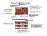
1
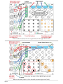
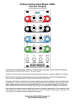
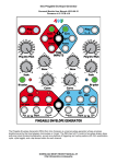
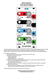
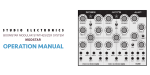
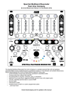
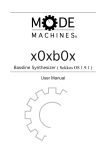
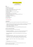
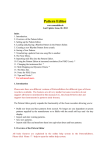
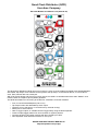
Quad Clock Distributor (QCD)
from 4ms Company
Eurorack Module User Manual v2.0 (2015-02-20)
The Quad Clock Distributor (QCD) from 4ms Company is a four channel Voltage Controlled Clock Divider/Multiplier
with master Tap Tempo. Each channel can be synced to the tap tempo, to the channel above, or to an external
clock. Each channel also has a reset jack.
With a Tap Tempo button and five sync'ed clock outputs, the QCD is a versatile head-of-the-chain "Master" clock
module, and/or a complex rhythmic pattern generator.
The QCD has headers for connecting to the QPLFO, VCA Matrix, and other modules.
•
•
•
•
•
•
•
•
Four CV Clock Divider/Multipliers (/32 to x16)
Tap Tempo button with dedicated tap clock output
Channels sync to tap tempo, or can be driven by external clock(s)
Reset jack on each channel
Gate or trigger outputs, or variable PW and Trigger Delay using the QCD Expander
Create complex trigger patterns for drum modules or rhythmic patches
Connects to QPLFO and other modules with the included 8-pin cable
QCD Expander adds attenuator/inverters for CV inputs
DOWNLOAD MOST RECENT MANUAL AT:
http://4mspedals.com/qcd.php
Basic features:
•
•
•
•
•
•
•
•
•
Four CV-controlled Clock Divider/Multipliers
◦ CV control allows for clock speed to be sequenced, manually changed, and/or self-patched for complex and
controllable patterns
◦ Divides and Multiplies clocks from /32 to x16 on each channel
▪ Detented knobs snap to integer division/multiples
▪ CV jacks modulate Div/Mult amount
▪ Channels can be stacked for more range (/1048576 to x65536)
Tap clock output jack runs at the tapped tempo even if other channels are being clocked externally
Independent CLOCK IN, OUT, Reset and Div/Mult CV on each channel
Reset jack restarts the clock when a trigger is received (alters phase of clock)
Clock input jacks are normalized downwards: Tap->Red->Black->Blue->Green
◦ Plugging into a CLK IN jack will clock the channel(s) below with the same clock
Auto-stop: each channel stops automatically when the incoming clock stops
LED brightness can be adjusted from the front panel
Jumper selectable gate or trigger outputs (QCD Expander adds CV control)
High-quality potentiometers with metal shafts and nuts
Connectivity:
•
•
•
•
•
Daisy chain multiple QCDs or other clock modules using Tap Out jack
Interfaces with QCD Expander for more features (Pulse Width, Inverted Gate, attenuverters for CV inputs)
8-pin header on the PCB connects to the Quad Pingable LFO (QPLFO) to provide four LFOs with CV control of Skew,
and CV control of the clock divide/multiply amount.
The 8-pin header can also interface with other modules (VCA Matrix, Mixiplexer, Intermix)
Can create a standard clock from a DINSYNC 24ppq clock and vice-versa, using two channels (/12 and /2, or x6 and
x4, for example).
Controls and jacks:
• Tap tempo button tap twice to set a tempo. If no external clocks are plugged in, it clocks all the channels
• TAP OUT jack: Clock output for the tapped tempo.
• Each of the 4 channels has:
• CLK IN jack: Clock input. Any signal can be used. A trim pot on the back sets the triggering threshold (default
is 2.5V). If nothing is plugged in, the clock is taken from the CLK IN jack on the channel above. The top
channel's CLK IN jack is normalized to the Tap clock.
• OUT jack: Clock output. Period (tempo) is a division or multiple of the time between the last two pulses on the
CLK IN jack
• Reset jack: Trigger input locks the clock phase to a new spot in the "measure". Any signal can be used. The
same triggering threshold for the CLK IN jack is used.
• Div/Mult: Knob selects amount of clock division or multiplication from /32 to x16, detenting/clicking at integer
amounts.
Note: /32 and x16 have two "clicks" each. Turning the knob all the way down is /32, and turning it up one click
is also /32. The next click is /16. Similarly, the top two clicks are x16. The artwork on the faceplate shows this.
• Div/Mult jack: 0V to 10V sweeps full range. Knob provides offset to the signal on the jack.
• LED: blinks to the tempo. Brightness is adjustable.
• LED Brightness: the small hole next to the TAP OUT jack is for adjusting the LED Brightness. A tiny phillips
screwdriver can be inserted through the panel to adjust the brightness. See manual section for instructions.
Dimensions
•
•
10 HP Eurorack format module
1.06” (27mm) deep
Power consumption
+12V rail:
53mA max with 5V Source jumper selecting external 5V
65mA max with 5V Source jumper selecting internal 5V
+5V rail:
13mA max with 5V Source jumper selecting external 5V
not used with 5V Source jumper selecting internal 5V
-12V rail:
40mA max
Page 2
Getting started
First, install the QCD in your Eurorack modular system. Use the included power cable to plug into the 16-pin header on a
standard Eurorack/Doepfer standard power supply. The red stripe should point down, and is -12V. Screw the QCD to the rails
on your case using the included M3 screws (or supply your own screws).
1. Start by tapping in a tempo. Press the Tap button twice.
Instantly, the button will flash to your tempo
All the channels are now synced to the tempo you tapped. If you tap a new tempo, all the lights will follow your
new rhythm. You can clear the tempo by holding down the Tap button for 1 second.
2. Plug the TAP OUT jack into something that makes sound.Try a bass drum module, or you could Ping
or trigger a PEG channel and run the ENV output into a VCA with a cool sound running through it.... This
will be your "metronome".
3. Plug the red OUT jack into something else that makes or changes sound. Maybe a hi-hat module, or
trigger a different envelope, or FM/waveshape a VCO.
4. Turn the red Div/Mult knob and listen to the different divisions and multiples of the clock.
For instance x3 will be triplets (or x12 will be triplets if you consider the tap clock to be quarter notes), and /4
will hit every 4th beat. Try to get familiar with the difference between x7 and x6, for example.
5. Plug external CV into the red Div/Mult CV jack.
Try the ENV out from a PEG running very slowly (turn the PEG Scale knob to about
2 o'clock).
Tip: Ping the PEG with the black OUT, and set black Div/Mult to /32 or /16.
Try a manual pad, such as the Pressure Points or a Synthwerks FSR module
(pressure output, not gate outputs).
Try a sequencer output. Each step in the sequencer can set a different
Divide/Multiply amount.
Tip: Clock the sequencer with the Tap Out or one of the QCD channels. Now everything will be synced. This is an easy way
to experiment with sequencing dance beats: changing rhythms rhythmically.
5. Turn the blue Div/Mult knob to "=" and plug the blue OUT into something
that makes sound.
Now we have 3 sounds going: a metronome (Tap Out), the red channel, and the
blue channel (which should be matching the metronome).
6. Trigger the blue Reset on the up-beat.
Run a manual trigger into blue Reset and fire it a fraction of a beat after you hear
the metronome. Listen to how the blue sound is still at the same tempo as the
metronome, but on an off-beat. Hit the trigger some more, and listen to how it
changes. This is called changing the phase of a clock. Play with Div/Mult, too.
Tip: To clear the reset, turn the knob up to x16 and back, or send a trigger into the
Div/Mult jack, or just stop and restart the clock (hold the Tap button for 1 second).
If you don't have a manual trigger like a Pressure Points or Synthwerks FSR, use a manual CV knob (MATHS Ch 2, or a
stopped PEG channel in Bi-polar mode) and turn the knob down/up/down to generate a trigger. Or do the "poor man's button":
plug/unplug a cable into any jack that's holding a high gate.
7. Make a shuffle beat by resetting the blue channel with the green
channel. This patch only works if the jumpers are set to Trigger Mode or you
have a QCD Expander with Pulse Width set to triggers. See the "Gate Mode
and Trigger Mode" section later in the manual.
Set blue Div/Mult to x5. Set green Div/Mult to x2. Patch green OUT into blue
Reset. The blue channel will output a swing pattern. Try green Div/Mult at x3,
then try x4. Try blue Div/Mult at x7.
• The green channel must be going slower than the blue channel (or else
you won't get a shuffle pattern)
• For best results, the two Div/Mult values should not be multiples of each
other (e.g. x3 and x5, not x2 and x4).
• Keep in mind that the slower channel must be resetting the faster
channel in order to generate a shuffle pattern (x3 -> x5, not x5 -> x3)
Tip: Try modulating the green Div/Mult a small amount with an LFO.... And/or
fire manual resets into the green channel...
Page 3
QCD and QPLFO
The QCD is designed to connect to the Quad Pingable
LFO, which turns the QCD's clocks into analogue
waveshapes (variable skew ramp, triangle, saw...)
Together, these two modules provide a fully clock-syncable,
variable-skew quad LFO and master clock system.
The QPLFO and QCD connect in the back with an 8-pin
ribbon cable. Connect the "PINGS" header on the QPLFO
to the "CLOCK OUTS" header on the QCD. Make sure the
red stripe is aligned to the white line on both modules.
When connected together, each QPLFO Ping jack is
normalized to the corresponding output on the QCD.
Whatever tempo each QCD channel is running at, the
QPLFO channel will run at the same tempo. Plugging into
the Ping on the QPLFO jack will override the QCD
connection, so the two units can still be used separately.
You can freely plug into the QCD's OUT jacks without
interrupting the connection.
QCD and VCA Matrix
The VCA Matrix is an excellent companion to the QCD. The four outputs of the QCD can be run into the four VCA Matrix
inputs. On the facing page are two example patch structures. One requires the QCD's jumpers to be in Trigger Mode, the
other requires them to be in Gate Mode (see "Gate Mode and Trigger Mode" section below).
Trigger routing (QCD in Trigger Mode)
Plug the four outputs of the QCD into the VCAM's four inputs (A/B/C/D). Plug the VCAM's four outputs (1/2/3/4) into four
triggerable modules (drum modules, or envelope triggers, for example).
• Make sure the QCD is in Trigger Mode because triggers can be combined more easily than gates.
• Turn up all the VCAM knobs
By turning on different combinations of buttons, various trigger patterns will come out of each VCAM channel. You can
combine two or more rhythms by turning on two or more buttons in a column. You can route a beat to multiple outputs by
turning it on in more than one row.
Self-modulating matrix: complex rhythmic pattern generator (QCD in Gate Mode)
Plug the four outputs of the QCD into the VCAM's four inputs (A/B/C/D). Plug the VCAM's four outputs (1/2/3/4) back into the
four Div/Mult jacks of the QCD. Make sure the QCD is in Gate Mode. If it's in Trigger Mode, this patch won't do very much!
The VCAM buttons will route the QCD channels into each other, and the VCAM knobs will adjust the amount each channel
effects the other(s). When you turn a button on, fine-tune the knob. Small changes in the knob can result in drastic
differences.
Each pattern of buttons/knobs causes a different set of rhythms. This is a very powerful patch structure that turns the
QCD+VCAM into a playable four-voice rhythm section. You can quickly build simple or complex beats and go between states
with the touch of a few buttons.
For outputs, you can designate one or more VCAM channels as your trigger pattern outputs (Output 4 in the diagram). Or you
can use stacking cables or mults to take the output from any QCD or VCAM channel, and also run that channel back into the
QCD Div/Mult.
Build the example patch on the facing page (top). Try turning on different buttons and adjusting the VCAM knobs by small
amounts. Make sure the QCD's jumpers are removed so that it's in Gate Mode. Try to understand how this patch works. For
instance, turning on button A-2 will route QCD channel 1 into QCD channel 2's Div/Mult. Thus channel 2 will go
fast/slow/fast/slow at a rate specified by channel 1's speed. The difference between "fast" and "slow" will be determined by
the A-2 knob on the VCAM.
Page 4
Trigger routing with QCD and VCA Matrix (see text on facing page).
Make sure the QCD's jumpers are set to Trigger Mode (see Gate/Trigger section below)
Self-modulating matrix: complex rhythmic pattern generator (see text on facing page)
Make sure the QCD's jumpers are set to Gate Mode (see Gate/Trigger section below)
Page 5
More Patch Ideas
QCD as master clock
Using the QCD as a master clock is easy. Just tap a tempo and all the channels will be in time! To chain multiple QCDs,
simply run the Tap Out jack into the next QCD's top channel CLK IN. To chain to other clock modules such as the Rotating
Clock Divider (RCD), run the Tap Out into the other module's main clock input.
QCD as clock slave
The QCD also functions as a clock slave. Run your master clock into the red CLK IN jack. All four QCD channels will be
clocked by the external clock, so you can select a different Div/Mult amount for each one. Plugging into one of the CLK IN
jacks will override the clock coming from above and drive the channels below. See "Clock normalization" for details.
QCD as complex trigger generator
Very complicated rhythmic patterns can be generated using the QCD with a VCA Matrix or a QCD Expander. See "QCD and
VCA Matrix" above, as well as the QCD Expander manual. If you don't have either of these two modules, you could use an
attenuator. A two or four-channel attenuator is great. Plug one QCD channel output into the attenuator, and run the output of
that into a different channel's Div/Mult CV jack. Adjust the attenuator knob to change how much the first channel modulates
the second.
Another useful companion to the QCD is the Short Bus from Low-Gain. This has diodes on the inputs to all for triggers to
combine easily. Patch in the four QCD channels and use the switches to route combinations of them to the two bus outputs.
Audio Rate Harmonizing
While the QCD is not designed to run at audio rates, it will process and produce low frequency audio signals. A simple signal
like a square or triangle will give the cleanest results, but any signal can be used. The output will be a harsh square wave, so
you may want to clean it up with some filtering or further processing.
The frequency response is complex. Running the QCD at high frequencies is an easy way to generate noise. The output pitch
is quantized past 300Hz or so. Sweeping the Div/Mult CV results in some interesting effects. Try mixing the original signal
back in. Try modulating Div/Mult at audio rates.
Note: It's recommended to be in Gate Mode use the QCD Expander when running at audio rates. The audio output in trigger
mode is dirty and becomes unstable more rapidly.
Gate Mode and Trigger Mode
Trigger Mode: Pulse width is about 12ms. Above 35Hz (audio Gate Mode. Pulse width is 50% of total period (square wave).
rate) the pulse width becomes unstable, unless you are using With the QCD Expander, this represents Pulse Width at 50%.
a QCD Expander (highly recommended!)
QCD Expander: all jumpers removed
Gate mode:
and ribbon cable connected to the
Install only the four required jumpers.
Expander module
(default setting)
The QCD can be set to Gate or Trigger Mode. In Trigger Mode, the outputs are 12ms pulses. In Gate Mode, the outputs are
square waves. The QCD Expander allows for variable Pulse Width (trigger, gates, or anything in between). For best results
(maximum control and most stable pulse widths), we recommend using the QCD Expander instead of setting the jumpers to
Trigger Mode.
The QCD ships from the factory in Gate Mode, with four extra jumpers included.
Trigger Mode:
Install all eight jumpers
Page 6
Clock normalization
The QCD's CLK IN jacks are normalized in a pattern that allows for one or more clocks to drive one or
more channels, or all the channels to sync to a single clock. See diagram at left.
All the channels are clocked by the tap clock unless you override that by plugging in an external clock.
Each channel is clocked by whatever is clocking the channel above. The top channel (red) is clocked
by the tap clock.
The two most common configurations are:
• Tap Tempo Master: No CLK IN jacks being used. The tap tempo clocks all the channels
• External Clock: plug an external clock into Red CLK IN. Leave other CLK IN jacks open
Another configuration example would be to run an external clock into the blue CLK IN jack. This will
clock the blue and green channels from the external clock. The red and black channels will still be
clocked by the Tap tempo clock.
Adjusting LED Brightness
The brightness of the LEDs can be adjusted from very dim
to very bright (producing a light show on your face).
You should leave the unit powered on to do this, so you
can watch the LEDs change. You will need a small
screwdriver (#0 size phillips tip, and 1/8" [3mm] or smaller
diameter shaft). Carefully insert the screwdriver into the
LED Adjustment hole as shown in the photo. Make sure
the screwdriver is perpendicular to the panel. You should
feel contact with the trim pot, which is a short distance
below the surface of the panel. Turn the screwdriver slowly.
If you turn all the way to the left (counter-clockwise) the
LEDs will turn almost off. If you turn all the way to the right
(clockwise) the LEDs will be painfully bright to view
(sunglasses optional).
If you're not sure if the screwdriver is the right size to turn
the trimpot, remove the QCD from the rack. The trimpot is
visible from the top edge of the module, so you can
visually inspect if the screwdriver is fitting. Forcing the
wrong screwdriver can damage the trimpot.
PCB v1.2 dims the channel LEDs only (red/black/blue/green)
PCB v1.3 and v2.0 and later dim the channel LEDs and also the Tap button.
Threshold Trimpot Adjustment
The trimpot on the back of the QCD adjusts the voltage required to trigger a clock
or reset. This trimpot is labelled "THRESHOLD” and is in the lower left corner. At
fully CCW, the voltage is 5.0V. At center, it's 2.5V. At fully CW it's 0V and the unit
will not respond to CLK IN or Reset.
The QCD can be interfaced with LZX-level compatible equipment by setting this
trimpot to about 0.5V.
If you need a precise triggering level, you can use a volt meter to measure the
voltage on the wiper of the trimpot as you turn it. This voltage will be the threshold
voltage.
Factory default is about 2.5V, or centered.
5V voltage source select
Near the power connector is a 3-pin header with a jumper. Jumping the side marked "INT"
will power the QCD from the +12V rail, using the internal regulator. Jumping the side
marked "EXT" will power part of the QCD from the +5V rail.
When the QCD is in "EXT" mode, less current is drawn from the +12V rail, but if there is
excessive noise on the 5V rail, it may cause the QCD to glitch. If you are experiencing
glitching, try setting the QCD to "INT".
Factory setting is "INT" mode.
Page 7
CLOCK OUTS header
At the top of the PCB there's a header labeled "OUTS". This connects the QCD's output
jacks to another module. The output jacks will still function and plugging into them will not
override or disconnect the header connection.
•
•
The OUTS header works with several modules:
• 4ms QPLFO: See above section "QCD and QPLFO".
• 4ms VCA Matrix: Connect the 8-pin cable to the "DAISYCHAIN INPUTS" header on
the VCAM. The QCD clocks will appear on the VCAM's main input jacks (not the CV
jacks). This replaces four 1/8" cables routed from the QCD outputs to the VCA Matrix
inputs.
• 4ms Shifting Inverting Signal Mingler (SISM): The QCD clocks will be routed to the
switch tabs of the SISM's input jacks. Be sure to remove the LINK jumpers on the SISM (see SISM manual).
Mixiplexer from Toppobrillo: Use individual connector wires available from Toppobrillo or 4ms. Pressing the X/I
button on the Mixiplexer selects the QCD's four clocks to control the four VCAs of the Mixiplexer. Level knobs on the
Mixiplexer attenuate the clocks. While a fun patch, it may be more useful to connect the QCD to a QPLFO, and the
QPLFO to the Mixiplexer.
Intermix from Circuit Abbey: Run the 8-pin cable to the left or right bank input on the Intermix. Set the Intermix to
L/R Bank mode. Set the QCD into Gate Mode. The four QCD clocks can be mixed, attenuated, and inverted to
produce a step-wave. Try patching this back into the one of the QCD's Div/Mult jacks!
BUS CLOCK jumpers
The QCD can send and receive clocks from other modules using the top rail of the power bus (commonly known as the Gate
bus in Doepfer systems). This feature is only available on the QCD v2.0 and later.
The QCD can act as a “master clock” or “leader” by sending clock pulses over the bus. Other modules that are configured to
receive (follow) a clock on the bus will be synchronized to the QCD, as if you had patched a cable between them. A nearly
infinite number of modules on the same power bus can be clocked from a single QCD, thus greatly simplifying your patches.
If set to receive/listen, the clock bus will be sent to the QCD's Channel 1 input (Red channel). This overrides the Tap Tempo
→ Channel 1 normalized connection. Thus to use Tap Tempo, you have to manually patch it into a QCD channel. The clock
bus can be overridden on the any receiving module by patching a cable into the clock input jack, so using the clock bus does
not create any limitations.
Compatible modules:
4ms QCD
4ms Rotating Clock Divider (RCD) v1.2 and later (receive only)
4ms Shuffling Clock Multiplier (SCM) v1.2 and later (receive only)
4ms Pingable Envelope Generator (PEG) v2.0 and later (receive only)
Makenoise CTRLSEL
Clock Send (Lead/Master):
The QCD will send a clock over the bus.
Put a jumper across Tap->Ch1, and across Ch1->Bus.
Omit Bus->Ch1.
Whatever you patch into the Channel 1 (Red) CLK IN jack will be
sent to the clock bus.
Tap Tempo will be sent to the clock bus if nothing is plugged into
the Channel 1 CLK IN jack.
Clock Receive (Follow/Slave):
The QCD will receive a clock from the clock bus.
Put a jumper across Bus->Ch1, and omit the other positions.
Channel 1-4 will be clocked from the Bus. The Tap Tempo section
will act like an independent module. To use the QCD with the Tap
Tempo button, you will have to patch from TAP OUT into the
CLK IN jack.
Stand-alone (Free):
The QCD will ignore the clock bus.
Put a jumper across Tap->Ch1, and omit the other two positions.
Tis mode is only recommended if you are using the bus for other
purposes (e.g: Doepfer CV/Gate bus).
Page 8