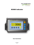
1
XR-8M and XR-12M
Alphanumeric Remote Displays
Installation Instructions
AWT35-500523
Issue AD
January 2011
© Avery Weigh-Tronix, LLC 2011. All rights reserved.
No part of this publication may be reproduced, stored in an electronic retrieval system, or transmitted in any form
or by any means, electronic, mechanical, photocopying, recording or otherwise without the prior written consent of
the copyright owner, or as permitted by law or under license. Full acknowledgment of the source must be given.
Avery Weigh-Tronix is a registered trade mark of the Avery Weigh-Tronix, LLC. This publication was correct at the
time of going to print however, Avery Weigh-Tronix, LLC reserves the right to alter without notice the specification,
design, price or conditions of supply of any product or service at any time.
All third party brands and product names used within this document are trademarks or registered trademarks of
their respective holders.
XR8M_12M_i_en_500523.book
Table of Contents
page
Chapter 1 General information and warnings ......................................................................................... 7
About this manual .............................................................................................................. 7
Text conventions ......................................................................................................... 7
Special messages ....................................................................................................... 7
Installation .......................................................................................................................... 8
Electrical installation .......................................................................................................... 8
Pluggable equipment ................................................................................................... 8
Permanently wired equipment - Isolator requirements ................................................ 8
Safe handling of equipment with batteries .................................................................. 9
Wet conditions ............................................................................................................. 9
Routine maintenance ......................................................................................................... 9
Cleaning the machine ........................................................................................................ 9
Training .............................................................................................................................. 9
Sharp objects ................................................................................................................... 10
FCC and EMC declarations of compliance ...................................................................... 10
Chapter 2 Introduction ............................................................................................................................ 11
Displays ........................................................................................................................... 12
Keypad ............................................................................................................................. 13
Opening the XR Enclosure .............................................................................................. 13
Lowering the Electronics Plate ......................................................................................... 14
Circuit Boards ............................................................................................................ 15
Chapter 3 Installation .............................................................................................................................. 16
Receiving Inspection ........................................................................................................ 16
Mounting Instructions ....................................................................................................... 16
Communications Wiring ................................................................................................... 17
Chapter 4 START-UP ............................................................................................................................... 20
Power ON/OFF ................................................................................................................ 20
Reset Button .................................................................................................................... 20
Auto-Learn ....................................................................................................................... 20
Learn Button .................................................................................................................... 21
Diagnostic Indicator Lights ............................................................................................... 21
Bargraph Function ........................................................................................................... 22
Chapter 5 Configuration Mode ............................................................................................................... 23
Entering Configuration Mode ........................................................................................... 23
Navigating Configuration Parameters .............................................................................. 23
Editing Configuration Parameters .................................................................................... 23
Exit & Save Configuration ................................................................................................ 24
Configuration Parameters ................................................................................................ 24
Parameter 1.0: Daytime Brightness Level ................................................................. 24
Parameter 1.1: Nighttime Brightness Level ............................................................... 24
Parameter 1.2: Power-Save Mode ............................................................................ 25
Parameter 1.3: Mirror Display Mode ......................................................................... 25
Parameter 1.4: Multi-Drop ID .................................................................................... 25
Parameter 1.5: Radio Channel Select ....................................................................... 26
Parameter 1.6: Utility Program Select ....................................................................... 26
Auto-learn Parameters ..................................................................................................... 26
Parameter 2.0: Manual Learn (Assisted Learn) ........................................................ 26
Parameter 2.1: Start-up Auto-Learn .......................................................................... 27
XR-8M and XR-12M Installation Instructions
3
Parameter 2.2: Leading Zero Suppression ............................................................... 27
Parameter 2.3: Set Scale Over ................................................................................. 27
Parameter 2.4: Lock Units ......................................................................................... 28
Parameter 2.5: Lock Weighing Mode ........................................................................ 28
Time / Date / Temp Parameters ....................................................................................... 28
Parameter 3.0: Time Display ..................................................................................... 28
Parameter 3.1: Date Display ..................................................................................... 29
Parameter 3.2: Temperature Display ........................................................................ 29
Parameter 3.3: Weight Display .................................................................................. 29
Parameter 3.4: Time Threshold ................................................................................. 29
DIagnostic Parameters .................................................................................................... 30
Parameter 9.0: Com Port .......................................................................................... 30
Parameter 9.1: String Counter .................................................................................. 30
Parameter 9.2: Baud Rate ......................................................................................... 30
Parameter 9.3: Configuration Lockout ....................................................................... 30
Parameter 9.4: Number Counter ............................................................................... 31
Parameter 9.8: Test Display ...................................................................................... 31
Parameter 9.9: Reset Defaults .................................................................................. 31
Chapter 6 Utility Programs ..................................................................................................................... 32
Program 0: Normal Operation .......................................................................................... 32
Program 4: Freeze Weight (Capture Print String) ............................................................ 32
Program 5: Command Mode (G2) ................................................................................... 32
Activating Command Mode ....................................................................................... 32
Transmit a Weight String ........................................................................................... 32
Transmit Status Characters ....................................................................................... 33
Transmit an Alphanumeric Message / Data String .................................................... 33
Control Commands ................................................................................................... 33
Sample Command Mode Data Strings ...................................................................... 34
Multi-Drop IDs & Networking ..................................................................................... 36
Chapter 7 Time & Date ........................................................................................................................... 37
Set Time & Date ............................................................................................................... 37
Adjust Time ............................................................................................................... 37
Adjust Date ................................................................................................................ 37
Battery Replacement ....................................................................................................... 38
Chapter 8 Wireless Setup ....................................................................................................................... 39
XR Integrated Wireless Installation .................................................................................. 39
Indicator & Wireless Transceiver ..................................................................................... 41
Wireless Connection Test ................................................................................................ 41
Chapter 9 Temperature Probe Installation ............................................................................................ 42
Chapter 10 Troubleshooting & Error Messages ................................................................................... 44
Chapter 11 Parts ...................................................................................................................................... 46
4
XR-8M and XR-12M Installation Instructions
Manual revision history
Current
Issue
Date Created
AA
May 2010
AB
August 2010
AC
November 2010
AD
January 2011
Details of Changes
New manual
minor changes
Added parts list and info on bargraphs
Corrected photo in Figure 8.1 and added Parameter 1.6 to Chapter 5.
XR-8M and XR-12M Installation Instructions
5
6
XR-8M and XR-12M Installation Instructions
1
General information and warnings
1.1
About this manual
This manual is divided into chapters by the chapter number and the large text at the top
of a page. Subsections are labeled as shown by the 1 and 1.1 headings shown above.
The names of the chapter and the next subsection level appear at the top of alternating
pages of the manual to remind you of where you are in the manual. The manual name
and page numbers appear at the bottom of the pages.
1.1.1 Text conventions
Key names are shown in bold and reflect the case of the key being described. This
applies to hard keys and onscreen or soft keys.
Displayed messages appear in bold italic type and reflect the case of the displayed
message.
1.1.2 Special messages
Examples of special messages you will see in this manual are defined below. The
signal words have specific meanings to alert you to additional information or the relative
level of hazard.
ELECTRICAL WARNING!
THIS IS AN ELECTRICAL WARNING SYMBOL.
ELECTRICAL WARNINGS MEAN THAT FAILURE TO FOLLOW
SPECIFIC PRACTICES OR PROCEDURES MAY RESULT IN
ELECTROCUTION, ARC BURNS, EXPLOSIONS OR OTHER HAZARDS
THAT MAY CAUSE INJURY OR DEATH.
WARNING!
This is a Warning symbol.
Warnings mean that failure to follow specific practices and procedures may
have major consequences such as injury or death.
CAUTION!
This is a Caution symbol.
Cautions give information about procedures that, if not observed, could result
in damage to equipment or corruption to and loss of data.
NOTE: This is a Note symbol. Notes give additional and important information, hints
and tips that help you to use your product.
XR-8M and XR-12M Installation Instructions
7
1.2
Installation
DANGER: RISK OF ELECTRICAL SHOCK. NO USER SERVICEABLE
PARTS. REFER TO QUALIFIED SERVICE PERSONNEL FOR SERVICE.
1.3
Electrical installation
CAUTION: The power cable must be connected to an earth-grounded electrical
outlet. The electrical supply must have a circuit breaker with an appropriate
rating to protect from over-current conditions.
For your protection, all electrical (110V or 230V) equipment used out of doors or
in wet or damp conditions should be supplied from a correctly fused power
source and protected by an approved ground fault protection device (RCD,
GFCI etc.)
IF IN DOUBT SEEK ADVICE FROM A QUALIFIED ELECTRICIAN.
1.3.1 Pluggable equipment
Pluggable equipment must be installed near an easily accessible socket outlet.
1.3.2 Permanently wired equipment - Isolator requirements
Permanently connected equipment must have a readily accessible disconnect device
incorporated in the fixed wiring such as an isolator or circuit breaker with at least 3mm
contact separation.
The isolator MUST NOT be installed into the flexible power cable supplied with the unit.
8
XR-8M and XR-12M Installation Instructions
1.3.3 Safe handling of equipment with batteries
CAUTION: Danger of explosion if battery is incorrectly replaced. Replace only
with the same or equivalent type recommended by the manufacturer. Dispose
of used batteries according to the manufacturer’s instructions.
ATTENTION: Il y a danger d'explosion s'il y a remplacement incorrect de la
batterie, remplacer uniquement avec une batterie du même type ou d'un type
équivalent recommandé par le constructeur. Mettre au rebut les batteries
usagées conformément aux instructions du fabricant.
1.3.4 Wet conditions
Under wet conditions, the plug must be connected to the final branch circuit via an
appropriate socket / receptacle designed for washdown use.
Installations within the USA should use a cover that meets NEMA 3R specifications
as required by the National Electrical Code under section 410-57. This allows the unit
to be plugged in with a rain tight cover fitted over the plug.
1.4
Routine maintenance
Always turn off the machine and isolate from the power supply before starting any
routine maintenance to avoid the possibility of electric shock.
Make sure that it is placed securely on a flat and level surface.
1.5
Cleaning the machine
Table 1.1 Cleaning DOs and DON’Ts
DO
DO NOT
Wipe down the outside of standard products Attempt to clean the inside of the machine
with a clean cloth, moistened with water and Use harsh abrasives, solvents, scouring cleaners or
a small amount of mild detergent
alkaline cleaning solutions
Spray the cloth when using a proprietary
cleaning fluid
1.6
Spray any liquid directly on to the display windows
Training
Do not attempt to operate or complete any procedure on a machine unless you have
received the appropriate training or read the instruction books.
XR-8M and XR-12M Installation Instructions
9
1.7
Sharp objects
Do not use sharp objects such as screwdrivers or long fingernails to operate the keys.
1.8
FCC and EMC declarations of compliance
United States
This equipment has been tested and found to comply with the limits for a Class A digital device, pursuant to Part 15 of the FCC Rules.
These limits are designed to provide reasonable protection against harmful interference when the equipment is operated in a
commercial environment. This equipment generates, uses, and can radiate radio frequency energy and, if not installed and used in
accordance with the instruction manual, may cause harmful interference to radio communications. Operation of this equipment in a
residential area is likely to cause harmful interference in which case the user will be required to correct the interference at his own
expense.
Canada
This digital apparatus does not exceed the Class A limits for radio noise emissions from digital apparatus set out in the Radio
Interference Regulations of the Canadian Department of Communications.
Le présent appareil numérique n’émet pas de bruits radioélectriques dépassant les limites applicables aux appareils numériques de
la Classe A prescrites dans le Règlement sur le brouillage radioélectrique edicté par le ministère des Communications du Canada.
European Countries
WARNING: This is a Class A product. In a domestic environment, this product may cause radio interference in which the user may be
required to take adequate measures.
10
XR-8M and XR-12M Installation Instructions
2
Introduction
The XR-8M and XR-12M remote displays incorporate the most features and highest
performance standards of any weighing display, making them the best choice for
remote viewing applications. The series has complete alphanumeric messaging
capabilities, an external keypad and standard time and date. Like all Avery WeighTronix products, the remote displays are designed with durability, functionality, and
versatility in mind.
If you should need technical assistance, please contact your local, authorized Avery
Weigh-Tronix distributor.
ATTENTION! Unauthorized installation and service of this unit may void the
warranty.
XR-8M and XR-12M Installation Instructions
11
2.1
Displays
Figure 2.1 shows the displays of the two models; XR-8M and XR-12M.
Figure 2.1 XR-8M and XR-12M displays
Model
# of Characters
Character Height
Character Matrix
XR-8M
8
4.0 inches
5x7
XR-12M
12
3.5 inches
5x7
The following annunciators appear on the display of each model:
12
l
GR = Gross weighing mode
l
NT = Net weighing mode
l
lb = Pounds
l
kg = Kilograms
XR-8M and XR-12M Installation Instructions
2.2
Keypad
The membrane keypad features an integrated light sensor window to detect changing
ambient light conditions and 3 tactile push buttons used to set time and date (see Set
Time & Date on page 37) as well as access configuration mode (see Entering
Configuration Mode on page 23).
Figure 2.2 Keypad
2.3
Opening the XR Enclosure
1.
Make sure the unit is disconnected from power.
2.
Remove the Phillips head screws from each side of the enclosure.
3.
Slowly, guide the front cover off of the main enclosure. See Figure 2.3..
Figure 2.3 Side view of opening the enclosure
XR-8M and XR-12M Installation Instructions
13
2.4
Lowering the Electronics Plate
1.
Remove the three (3) captive screws holding the electronics plate to the main
enclosure. See Figure 2.4.
Figure 2.4 Open enclosure
2.
Slowly, allow the electronics plate to swing down. The controller board and
power supply board are now accessible for installation, wiring and service. See
Figure 2.5.
Figure 2.5 Electronics plate down
14
XR-8M and XR-12M Installation Instructions
2.4.1 Circuit Boards
Display Boards
Figure 2.6 Display Boards
Controller Board
Power Supply Board
Surge Suppression Board
Figure 2.7 Controller and power boards
XR-8M and XR-12M Installation Instructions
15
3
Installation
3.1
Receiving Inspection
It is always good practice to verify that the XR display is complete and undamaged
upon receipt.
3.2
l
Check over packaging for any signs of damage.
l
Remove the XR display from its protective packaging and check for damage.
l
Verify that the shipment includes:
m
XR display (complete and intact)
m
XR Installation Manual
Mounting Instructions
Dimensions and mounting-hole patterns for the XR display (XR-8M & XR-12M) are
given in Figure 3.1.
Figure 3.1 Dimensions and hole pattern
1.
Inspect the installation site for properly grounded power. The socket-outlet shall
be installed near the equipment and shall be easily accessible.
2.
Ensure that mounting structures will bear the weight of the display (XR-8M &
12: 26.5 lb / 12 kg).
3.
Allow proper clearance for lifting and removing the front cover.
4.
Use proper hardware, including wall anchors, where necessary, when
mounting the enclosure. The hex cap bolt length is specified as minimum. The
appropriate length must be determined specifically for each application.
Imperial:
5/16-18 UNC Hex Cap Bolts - 4pcs/unit (min. 1" long)
5/16 Steel Flat Washer - 4pcs/unit
Metric:
M8x1.25 Hex Cap Bolts - 4pcs/unit (min. 25mm long)
M8 Steel Flat Washer - 4pcs/unit
16
XR-8M and XR-12M Installation Instructions
5.
Run communication cables up into the enclosure via strain reliefs as
necessary. See Figure 3.2.
Figure 3.2 Strain reliefs
3.3
Communications Wiring
All communications wiring terminates at the controller board. See Figure 3.3.
Communications should be wired before applying power to the unit.
J3
J4
J5
20 mA
Mode
Switch
(SW10)
Figure 3.3 Communication terminals
RS-232 Wiring
Terminate the indicator’s communication wires at the RS-232 terminal (J3). See Fig.
3.3 and the table below:
XR-8M and XR-12M Installation Instructions
17
RS-232 Daisy Chain / Multi-Drop Wiring
RS-485 / 422 Wiring
Terminate the indicator’s communication wires at the RS-485 terminal (J4). See Fig.
3.3 & table below:
RS-485 Daisy Chain / Multi-Drop Wiring
Parallel Wiring
Split Wiring
20 mA Current Loop Wiring
Terminate the indicator’s communication wires at the 20 mA Current Loop terminal (J5).
See Fig. 3.3 & table below:
18
XR-8M and XR-12M Installation Instructions
20 mA Current Loop Mode Switch
After the current loop is wired, ACTIVE or PASSIVE mode must be
selected via the switch on the controller board (SW 10). See illustration at
left.
Select ACTIVE if the XR is required to supply the 20 mA current to the
communicating device (indicator).
Select PASSIVE if the communicating device (indicator) supplies the
current to the XR display. If unsure of these requirements, check the
device’s manual.
XR-8M and XR-12M Installation Instructions
19
4
START-UP
4.1
Power ON/OFF
The XR has no ON/OFF button or switch. Plugging the unit into AC power will turn the
unit ON. Disconnecting AC power will turn the unit OFF.
Once power is applied, the XR performs a self test by counting up 1 to 9, flashing
annunciators and decimals, and displaying the software revision number (Ex. 4-00).
4.2
Reset Button
The RESET button on the controller board allows technicians to cycle power on the unit
without disconnecting/connecting AC power. See Figure 4.1
Figure 4.1 RESET button on controller board
4.3
Auto-Learn
On power up, the XR automatically enters Auto-Learn Mode, analyzing the serial
communications settings and incoming data from the indicator.
The output string must contain number characters. An STX character (ASCII 02) and/
or CR character (ASCII 13) must also be included.
Auto-Learn Examples:
123456<SP><UM><CR>
<STX>123456<CR>
nk 12345 <CR>
The data string for Auto-Learn must terminate with a <CR>
Once Auto-Learn is successful (about 10 seconds after power up) the current weight is
displayed.
Automatic Start-up Auto-Learn may be disabled for custom applications. Please see
Auto-learn Parameters on page 26.
20
XR-8M and XR-12M Installation Instructions
4.4
Learn Button
If Automatic Start-up Auto-Learn is disabled, the LEARN button on the controller board,
see Figure 4.2, must be pressed to enter Auto-Learn Mode.
Figure 4.2 LEARN button
4.5
Diagnostic Indicator Lights
The XR has 7 diagnostic indicator lights located on the controller board. Each is pointed
out in Figure 4.3.
3.3V Light:
Turns ON when voltage is supplied to the controller board.
12V Light:
Turns ON when voltage is supplied to the Display boards.
STATUS Light:
The XR’s “heartbeat”. BLINKS when the processor is running.
Rapid blinking (3 times per second) indicates that the XR is in
Auto-Learn Mode, attempting to interpret a data string.
Regular blinking (Once per second) indicates that the XR has
successfully learned a data string and is running properly.
RS232 Light:
FLASHES ON each time the XR receives a character through the
RS232 com port.
RS485 Light:
FLASHES ON each time the XR receives a character through the
RS485 com port.
20mA Light:
FLASHES ON each time the XR receives a character through the
20 mA Current Loop port.
RADIO Light:
FLASHES ON when the XR’s Radio Module receives data.
This light will only illuminate if the Radio Module is installed.
XR-8M and XR-12M Installation Instructions
21
Figure 4.3 Controller board diagnostic lights
4.6
Bargraph Function
There is a bargraph feature in the XR remote displays. This allows you to graphically
represent the weight as a bargraph on the display.
To setup the bargraph see Control Commands on page 33 and Sample Command
Mode Data Strings on page 34.
To disable bargraph, set both MIN and MAX weights to “0” in Control Commands on
page 33.
Set the minimum and maximum weights you want displayed and as the weight
increases or decreases, the bargraph will move across the display. Halfway between
the MIN and MAX weight the bargraph will be at 50% (independent of scale units).
22
XR-8M and XR-12M Installation Instructions
5
Configuration Mode
5.1
Entering Configuration Mode
1.
Press & hold the UP and DOWN ARROW keys together.
2.
ConFig is flashed on the display.
3.
The first configuration mode parameter (P1.0) is displayed.
In configuration mode, if no keys are pressed for 10 seconds, the scale weight is
displayed with a blinking “C” on the left-hand side.
5.2
Navigating Configuration Parameters
Use the UP and DOWN ARROW keys to find the parameter. Configuration parameters
are displayed by the letter P preceding the parameter number
(Ex. P1.0, P1.1, P1.2 …”).
Hold down the UP or DOWN ARROW key for more than 1 second to scroll through
the configuration sub-blocks for quicker navigation (Ex. P1.0, P2.0, P3.0 ...”).
5.3
Editing Configuration Parameters
1.
Navigate to the parameter and press ENTER to display the parameter value.
2.
Use the UP and DOWN ARROW keys to edit the parameter value.
3.
Press ENTER to confirm the parameter value.
XR-8M and XR-12M Installation Instructions
23
5.4
5.5
Exit & Save Configuration
1.
Press the UP and DOWN ARROW keys together.
2.
The display flashes SAvE and rESEt before exiting configuration mode. All
configuration information is saved and the display resets itself for normal
operation.
Configuration Parameters
5.5.1 Parameter 1.0: Daytime Brightness Level
Factory default settings are indicated by a left arrow (<) in the tables below.
Value
Description
0 = Low
1 = Med Low
2 = Med High
3 = High <
Set the brightness of the display for daytime viewing. The
built-in light sensor automatically detects daylight conditions
and sets the display brightness to this level.
5.5.2 Parameter 1.1: Nighttime Brightness Level
Value
Description
0 = Low <
1 = Med Low
2 = Med High
3 = High
Set the brightness of the display for nighttime viewing. The
built-in light sensor automatically detects night conditions
and sets the display brightness to this level.
Lowering the brightness level at night helps reduce nighttime glare and energy costs.
Passing headlights, spotlights, etc. will NOT activate the daytime brightness level.
24
XR-8M and XR-12M Installation Instructions
5.5.3 Parameter 1.2: Power-Save Mode
Value
Description
0 = OFF
1 = ON <
Automatically dims display brightness one level below the
selected brightness level (day or night, as applicable) if there is
no activity on the scale for 10 minutes. Brightness levels are
restored when motion is detected on the scale. This feature
saves power and increases LED longevity.
5.5.4 Parameter 1.3: Mirror Display Mode
Value
Description
0 = OFF <
1 = Mirror
2 = Cycle
Mirror display for viewing from a vehicle’s rear-view or side-view
mirrors. When “Cycle” is selected, the display will cycle between
Normal and Mirror Display Modes every 5 seconds.
5.5.5 Parameter 1.4: Multi-Drop ID
Value
Description
0= ID 0 <
1= ID 1
2= ID 2
3= ID 3
Etc.
Sets the unit ID if multiple remote displays are networked together. Up
to four (4) XR displays can be networked on a single serial or radio
connection. Messages are sent to individual displays using control
codes and these IDs. For Multi-Drop instructions, see Multi-Drop IDs &
Networking on page 36.
If Multi-Drop is not being used, it is very important that the Multi-Drop ID be set to 0.
XR-8M and XR-12M Installation Instructions
25
5.5.6 Parameter 1.5: Radio Channel Select
Value
Description
0 = Ch 0 <
1 = Ch 1
2 = Ch 2
3 = Ch 3
4 = Ch 4
5 = Ch 5
Sets the radio frequency channel (0-5) for the optional Integrated
Wireless Module. If there are multiple scale/remote display
installations at a given site, each installation must have its own
unique radio channel selected to prevent interference.
The XR remote display must be set to the same radio channel as the scale indicator’s
wireless transceiver.
If the wireless connection experiences interference problems from another radio site,
switching radio channels will most likely correct the problem.
5.5.7 Parameter 1.6: Utility Program Select
5.6
Value
Description
0 = OFF<
1 = Pgm 1 - Green light at 0
2 = Pgm 2 - Red light on motion
3 = Pgm 3 - Normal w/ Cmds
4 = Pgm 4 - Freeze weight
5 = Pgm 5 - Command mode-G2
Etc.
Several Utility Prorams are pre-installed in the XR remote display.
For a complete list of programs and descriptions, see Utility
Programs on page 32.
Auto-learn Parameters
5.6.1 Parameter 2.0: Manual Learn (Assisted Learn)
Value
Description
Lxxxxx
Manual Learn activates Auto-Learn Mode from inside configuration
mode. The remote display will analyze and attempt to learn the string.
The message “LEARN” will be displayed. When the remote display is
successful, the weight will be shown on the display.
A blinking L will be displayed in the left hand corner to indicate you are
still in learning mode.
To lock in the learned string’s settings, press ENTER.
26
XR-8M and XR-12M Installation Instructions
5.6.2 Parameter 2.1: Start-up Auto-Learn
Value
Description
0 = OFF
1 = ON <
The XR automatically enters Auto-Learn Mode on start up. If
OFF, the display will startup using settings stored in memory
from the last learn.
Parameter 2.0 must be activated or the LEARN button on the
controller board must be pressed before the XR will go into
Auto-Learn Mode again.
5.6.3 Parameter 2.2: Leading Zero Suppression
Value
Description
0 = OFF <
1 = ON
In some cases, the scale indicator may transmit leading
zeros in the output string. If leading zeros are NOT
required, they may be suppressed. The XR will
automatically remove the leading zeros and replace them
with blank spaces on the display.
Leading Zeros may also be disabled using the scale indicator (if possible).
5.6.4 Parameter 2.3: Set Scale Over
Value
Description
0 = Auto <
Value for scale
over target
weight.
If there is no scale over status character in the weight string, or the
indicator continues to transmit past maximum capacity, the unit can be
set to blank the display when the weight goes past a preset weight
value.
Use the UP/DOWN keys to set the weight threshold and press
ENTER. Holding the keys down will cause the weight threshold to
change in steps of 10000. Single key presses will cause the weight
threshold to change in steps of 100.
XR-8M and XR-12M Installation Instructions
27
5.6.5 Parameter 2.4: Lock Units
Value
Description
0 = Auto <
1 = lb ON (or t)
2 = kg ON
3 = Both OFF
Weight Units (lb, kg, and t) are automatically displayed from
the indicator’s output string. The Units annunciators may be
locked on or off as required.
On European models the lb enunciator is replaced with t.
5.6.6 Parameter 2.5: Lock Weighing Mode
5.7
Value
Description
0 = Auto <
1 = Gross ON
2 = Net ON
3 = Both OFF
Weighing Mode (Gross/Net) is automatically displayed
from the indicator’s output string. The Mode
annunciators may be locked on or off as required.
Time / Date / Temp Parameters
XR displays can cycle between displaying weight, time and date every 5 seconds
when: a) the weight display is at zero AND; b) there is no activity on the scale for the
selected time period.
5.7.1 Parameter 3.0: Time Display
28
Value
Description
0 = OFF <
1 = Time (AM/
PM)
2 = Military (24
Hour)
Activates the TIME function in 12 hour
or 24 hour clock formats.
XR-8M and XR-12M Installation Instructions
5.7.2 Parameter 3.1: Date Display
Value
Description
Activates the DATE function in US, ISO
0 = OFF <
1= MMDDYY (US or UK format.
Format)
2 = YYMMDD
(International)
3 = DDMMYY
(UK)
5.7.3 Parameter 3.2: Temperature Display
Value
Description
0 = OFF <
1 = °F (degrees
Fahrenheit)
2 = °C (degrees
Celsius)
Activates the temperature function
(in °F or °C) when the optional
temperature probe is installed.
5.7.4 Parameter 3.3: Weight Display
Value
Description
0 = OFF
1 = Cycle
2 = No Cycle <
OFF: Weight will NOT BE DISPLAYED at all.
ON: Weight is displayed in the “Time/Date/Temp/Weight Cycle”.
No Cycle: Weight is NOT in the “Time/Date/Temp/Weight Cycle”.
5.7.5 Parameter 3.4: Time Threshold
Value
Description
1 to 20 min.
1 min <
Selects the number of minutes that the scale must be at zero
before the “Time/Date/Temp/Weight Cycle” is displayed.
XR-8M and XR-12M Installation Instructions
29
5.8
DIagnostic Parameters
5.8.1 Parameter 9.0: Com Port
Value
Description
0 = RS232
1 = RADIO
2 = 20mA
3 = RS485
Displays the currently active Com Port.
5.8.2 Parameter 9.1: String Counter
Value
Description
0 to 65535
Counter indicates the number of characters
received. Counter rolls over after 65535.
5.8.3 Parameter 9.2: Baud Rate
Value
Description
300
600
1200
4800
9600
19200
Displays the baud rate currently being
utilized for serial communications.
5.8.4 Parameter 9.3: Configuration Lockout
30
Value
Description
0 = Disabled <
1 = Enabled
When enabled, no configuration parameters can be
changed. Disable this parameter to allow changes.
XR-8M and XR-12M Installation Instructions
5.8.5 Parameter 9.4: Number Counter
Value
Description
0 to 65535
Counter indicates the number of numeric characters
received. Counter rolls over after 65535.
5.8.6 Parameter 9.8: Test Display
Value
N/A
Description
Cycles through
time, digits,
annunciators &
decimal
characters (as
applicable).
5.8.7 Parameter 9.9: Reset Defaults
Value
Description
0 = Do Not Reset
1 = RESET
Resets Configuration Parameters to factory defaults.
XR-8M and XR-12M Installation Instructions
31
6
Utility Programs
The XR displays have several auxiliary functions that may be activated via Parameter
1.6 in configuration mode.
6.1
Program 0: Normal Operation
l
6.2
No Utility Program is selected.
Program 4: Freeze Weight (Capture Print String)
l
This program is useful in applications where a weight value must be
displayed regardless of what is happening on the scale.
l
A weigh ticket (using ASCII characters) must be created on the scale
indicator that sends the scale weight and a <CR> character to the XR
display with a button press.
Example:
l
123456 lb g<CR>
When the XR receives the ticket, it displays the weight and keeps displaying
it until the next weigh ticket is received.
This application assumes a legal-for-trade indicator is used to send the weigh ticket.
Please review local Weights and Measures requirements.
6.3
Program 5: Command Mode (G2)
All XR displays can be setup to receive commands directly from the scale system or
PC. Supported commands include transmitting weights, basic alphanumeric
messaging, and additional display functions.
Command Mode disables Auto-Learn and fixes communications at 9600-N-8-1. The
XR looks only for specific commands sent by the indicator or scale controller.
6.3.1 Activating Command Mode
To enable Command Mode for the XR-8M and XR-12M, set Parameter 1.6 in
configuration mode to 5.
6.3.2 Transmit a Weight String
Use numeric ASCII characters followed by a <CR> character. Weights are displayed
from right to left.
Example:
l
32
To display 1000, transmit: 1000<CR>
XR-8M and XR-12M Installation Instructions
6.3.3 Transmit Status Characters
Status characters may be embedded anywhere in the weight string to control the
annunciator lights. Status characters may be upper or lowercase, and in any order,
before or after the weight.
STATUS COMMAND
ASCII
DECIMAL
GROSS weight
G or g
71 or 103
NET weight
N or n
78 or 110
POUNDS
L or l
76 or 108
KILOGRAMS
K or k
75 or 107
Example: To display 1000 lb gross, transmit: 1000LG<CR> OR gl1000<CR>
If no gross/net character is sent, the “GR” annunciator will illuminate by default.
6.3.4 Transmit an Alphanumeric Message / Data String
When in Command Mode, XR models can display the entire printable ASCII character
set and scrolling messages. When an alphanumeric data string is longer than the unit’s
number of display characters, the message will scroll (right to left). The maximum data
string length is 40 characters.
Alphanumeric message data strings must be preceded by the “ character (decimal 34)
and followed by a Carriage Return <CR> character (decimal 13) to differentiate them
from weight strings. Characters are displayed from left to right.
6.3.5 Control Commands
Control commands are ASCII characters (preceded by @ and followed by <CR>) that
are transmitted to the XR to control additional features.
CONTROL COMMAND
ASCII
DECIMAL
Turn ON flashing display
(
40
Turn OFF flashing display
)
41
FLASH display 3 times
!
33
Scroll speed (0, fastest to 9, slowest)
=
61
MINIMUM weight for bargraph
>
62
MAXIMUM weight for bargraph
<
60
XR-8M and XR-12M Installation Instructions
33
6.3.6 Sample Command Mode Data Strings
DATA STRING
DISPLAY
0<CR>
“0” gross
1000 <CR>
“1000” gross
LN 1234 <CR>
“1234” lb net
1234 L g <CR>
“1234” lb gross
“hello<CR>
“hELLo”
“XR-8M<CR>@!<CR>
“XR-8M” flashing 3 times
“Avery Weigh-Tronix<CR>
“Avery Weigh-Tronix” scrolling
“Avery Weigh-Tronix!<CR>
“Avery Weigh-Tronix!” scrolling
@=9<CR>“Avery Weigh-Tronix<CR>
“Avery Weigh-Tronix” slow scroll
123456<SP><UM><CR>
6 digits of weight with leading spaces,
Unit of measure.
@>0<CR>@<5000<CR>
*Bargraph will display from 0 to 5000.
Example: At 2500, the bargraph will be at
50% (independent of scale units).
* To disable bargraph, set both MIN and MAX weights to “0”.
34
XR-8M and XR-12M Installation Instructions
Displayable Alphanumeric Character Set:
Control
Character
ASCII
Code #
Control
Character
ASCII
Code #
Control
Character
ASCII
Code #
!
33
A
65
`
96
"
34
B
66
a
97
$
36
C
67
b
98
%
37
D
68
c
99
&
38
E
69
d
100
'
39
F
70
e
101
(
40
G
71
f
102
)
41
H
72
g
103
*
42
I
73
h
104
+
43
J
74
i
105
,
44
K
75
j
106
-
45
L
76
k
107
.
46
M
77
l
108
/
47
N
78
m
109
0
48
O
79
n
110
1
49
P
80
o
111
2
50
Q
81
p
112
3
51
R
82
q
113
4
52
S
83
r
114
5
53
T
84
s
115
6
54
U
85
t
116
7
55
V
86
u
117
8
56
W
87
v
118
9
57
X
88
w
119
:
58
Y
89
x
120
;
59
Z
90
y
121
<
60
[
91
z
122
=
61
\
92
>
62
]
93
?
63
^
94
@
64
_
95
XR-8M and XR-12M Installation Instructions
35
6.3.7 Multi-Drop IDs & Networking
XR displays using Multi-Drop networking must be in command mode. The Multi-drop
ID (0 to 3) must also be set (see Parameter 1.4: Multi-Drop ID on page 25).
When using Multi-drop, the XR will only respond after it has been selected.
To select a display, transmit a # character (ASCII 35) followed by the correct ID number
and a <CR> character (ASCII 13). Once this command is executed, control codes,
alphanumeric messages and weight strings can be transmitted to the selected display
as described in Program 5: Command Mode (G2) on page 32.
An XR will remain selected until it receives a command containing a different ID.
Examples:
1.
Select Multi-drop ID 1:
Transmitting “#1<CR>” selects the display with ID #1.
2.
Select Multi-drop ID 3 and send a weight of 1000lb gross:
“#3<CR>”
“1000LG<CR>
The ID number may also be embedded with the weight string:
“#3 1000LG<CR>
3.
Send 3 different weights to 3 different scoreboards:
“#0 2000LG<CR>#1 3000LG<CR>#2 5000LG<CR>“
4.
Send the text “hello” to scoreboard ID 3.
“#3”HELLO<CR>
36
XR-8M and XR-12M Installation Instructions
7
Time & Date
The XR display has a precision time clock that compensates for variable temperature
conditions. The battery on the controller board (J22) provides back-up power for this
clock.
7.1
Set Time & Date
7.1.1 Adjust Time
1.
Make sure Time is enabled in configuration mode (Parameter 3.0)
2.
Press and hold the UP ARROW/TIME key.
3.
Use the UP and DOWN ARROW keys to select the correct hour and press
ENTER.
4.
Repeat for minutes and AM/PM if enabled (12 hour clock).
7.1.2 Adjust Date
1.
Make sure Date is enabled in configuration mode (Parameter 3.1)
2.
Press the DOWN ARROW/DATE key.
3.
Use the UP and DOWN ARROW keys to select the correct year/month/day
(International) or month/day/year (USA) and press ENTER.
XR-8M and XR-12M Installation Instructions
37
7.2
Battery Replacement
The XR displays use a 3 Volt lithium battery. Power is drawn from the battery only when
the unit is disconnected from AC power. If time and date are lost when the unit is
disconnected from AC power, the battery likely needs replacement. See Figure 7.1.
Figure 7.1 Battery on the controller board
1.
Remove the old battery from the J22 terminal on the controller board by hand.
2.
Observe proper battery polarity before inserting new battery.
3.
Ensure the battery is seated correctly in the J22 terminal.
CAUTION! Risk of explosion if battery is replaced by an incorrect type. Dispose
of used batteries according to their instructions.
CAUTION! Never use metal objects such as screwdrivers to remove batteries!
This may result in personal injury or damage to the unit.
38
XR-8M and XR-12M Installation Instructions
8
Wireless Setup
8.1
XR Integrated Wireless Installation
The Integrated Wireless Kit includes:
l
l
l
l
Radio Module
External Antenna
Internal Antenna Cable
FCC/Industry Canada Sticker
1.
Ensure the XR display is disconnected from power and open the enclosure.
2.
Place the radio module in the “Radio Module Option” terminals on the
controller board.
3.
Connect the internal antenna cable to the threaded SMA terminal on the radio
module.
4.
Remove the rubber plug in the bottom of the XR enclosure. See Figure 8.1
Figure 8.1 Rubber plug
5.
Remove the nut and lock washer from the threaded SMA terminal on the
internal antenna cable. Run the threaded SMA terminal through the hole in the
bottom of the XR enclosure. Use the lock washer and nut to secure the SMA
terminal.
6.
Connect the external antenna to the SMA connector on the bottom of the
enclosure.
XR-8M and XR-12M Installation Instructions
39
7.
Power up the XR. The XR is ready to receive radio signals.
Figure 8.2 Radio module on controller board
Figure 8.3 Wireless kit installation
40
XR-8M and XR-12M Installation Instructions
8.2
Indicator & Wireless Transceiver
1.
Wire the ScaleLink Transceiver to the indicator (or other communicating
device).
2.
Verify communication settings between the ScaleLink and the indicator (or
other communicating device). The ScaleLink’s default communication settings
are:
l
l
l
l
8.3
Baud Rate
Data Bits
Parity
Stop Bits
9600
8
None
1
3.
Ensure the indicator is set-up to output continuously.
4.
Power up the Indicator and transceiver together to transmit radio signals.
Wireless Connection Test
1.
Verify that both the Wireless Transceiver and the XR Remote Display are set to
the same radio channel.
2.
Verify that the Wireless Transceiver is ON and transmitting.
3.
Verify that the Radio LED on the XR controller board is flashing. See Figure
8.4.
Figure 8.4 RADIO LED on the controller board
4.
Add weight to the scale.
5.
Verify that the XR is correctly displaying Weight, Measurement Units (kg, lb),
and Weighing Mode (GR, NT) as shown on the scale indicator.
If the XR’s readings are incorrect, erratic, or very slow, a different radio channel may
need to be selected.
XR Radio Module Field Installation kits are available. Please contact the your Avery
Weigh-Tronix distributor for more information.
XR-8M and XR-12M Installation Instructions
41
9
Temperature Probe Installation
1.
Unpack the optional Temperature Probe Assembly. This assembly consists of
the weather-sealed temperature probe contained in a strain relief. A 4 conductor
cable runs from the temperature probe to a 4 pin connector.
2.
Ensure the XR display is disconnected from power and open the enclosure.
3.
Remove the rubber plug from the hole in the bottom of the enclosure.
4.
Remove the nut from the strain relief and run the cable up through the hole in
the bottom of the enclosure.
5.
Run the connector and cable through the nut and use it to fasten the strain
relief to the enclosure.
6.
Plug the temperature probe connector into the terminal (J9) on the controller
board.
7.
Power up the XR display. Enter configuration mode and set Parameter 3.2 to 1
for Fahrenheit or 2 for Celsius.
8.
Exit configuration mode. The temperature will be displayed once the remote
display has been reading zero for the time specified in Parameter 3.4 (Time
Threshold).
Figure 9.1 Temperature probe installation
42
XR-8M and XR-12M Installation Instructions
Figure 9.2 Temperature probe cable connects to J9 on the controller board
The XR’s Digital Temperature Probe ensures accuracy to within ±1 degree and will
never need to be calibrated.
XR-8M and XR-12M Installation Instructions
43
10 Troubleshooting & Error Messages
Problem
Cause and/or Probable Solution
Unit won’t power up:
•
•
•
•
Unit has power, but there is
no display.
•
•
•
Dashes across the display.
•
•
•
•
Display reads Err 1.
•
•
•
•
Display reads Err 2.
•
•
•
•
Verify ribbon cable connections from controller board
to the 2 display boards.
Check 12V light and fuse on controller board.
If the unit is in COMMAND mode, the display will
remain blank until data is received.
Communications have failed.
Verify the correct terminal (RS-232, 422/485, 20 mA)
is being used and check wiring.
Verify cable or radio connection to indicator.
Verify indicator serial port function
Baud Rate Auto-Learn has failed.
Verify the correct terminal (RS-232, 422/485, 20 mA)
is being used.
Verify cable to indicator.
Verify that data is being transmitted to the XR from
the indicator and that the data string contains numeric
characters.
Data String Auto-Learn has failed or Radio not
receiving.
Verify the correct terminal (RS-232, 422/485, 20 mA)
is being used.
Verify cable or radio connection to indicator.
Verify that a data string is being sent to the XR from
the indicator and that the data string contains either
an STX character (ASCII 02) or a CR character
(ASCII 13).
Display reads Err 3.
•
The XR is receiving data on multiple communications
ports.
STATUS light NOT blinking
(OFF)
•
Verify that unit has power. When powered, if the
Status light remains OFF, the processor is not
running.
STATUS light blinking fast
(3/second) for longer than
30 seconds:
•
The XR is not able to Auto-Learn the data string or
baud rate. See Error Messages Err 1 and Err 2.
RS232 light not flashing
•
Verify the RS232 terminal is being used and check
communications wiring at the indicator.
Verify that data is being sent to the XR from the
indicator and that the data string contains numeric
characters.
•
44
Verify AC power source (Outlets, breakers, etc.)
Check power cord connections to terminal block and
ground posts inside the main enclosure.
Verify internal power wiring from terminal block to the
power supply board and power supply board to the
controller board.
Check fuse on power supply board and controller
board.
XR-8M and XR-12M Installation Instructions
RS485 light not flashing:
•
•
20mA light not flashing:
•
•
•
RADIO light not flashing:
•
•
XR-8M and XR-12M Installation Instructions
Verify the RS485 terminal is being used and check
communications wiring at the indicator.
Verify that data is being sent to the XR from the
indicator and that the data string contains numeric
characters.
Verify the 20mA terminal is being used and check
communications wiring at the indicator.
Verify that data is being sent to the XR from the
indicator and that the data string contains numeric
characters.
Make sure the correct mode (ACTIVE or PASSIVE) is
selected on the controller board (SW10).
Check that the radio module is properly installed.
Ensure that the internal antenna cable is connected
to the radio module and the external antenna.
No data is being sent from the wireless transceiver
connected to the scale indicator.
45
11 Parts
Part Number
Description
XR-8M ONLY:
AWT20-504328
XR-8M DISPLAY BOARD, QTY 2 PER UNIT
XR-12M ONLY:
AWT20-504329
XR-12M DISPLAY BOARD, QTY 2 PER UNIT
PARTS COMMON TO BOTH:
AWT20-504327
XR-8M/12M CONTROLLER BOARD
AWT20-504391
XR-8M/12M ENCLOSURE
AWT20-504331
XR-8M/12M FRONT COVER
AWT20-504332
XR-8M/12M ELECTRONICS MTG PLATE
AWT20-504333
XR-8M/12M NON-GLARE LENS
60339-0022
BREATHE VENT
AWT25-500616
EXTERNAL KEYPAD W/ LIGHT SENSOR
60339-0048
POWER SUPPLY
60339-0055
11" RIBBON CA
60339-0063
21" RIBBON CA
60339-0071
9" GND WIRE
60339-0089
11" GND WIRE
60339-0097
POWER SUPPLY TO CONTROLLER BOARD CABLE ASSEMBLY
60339-0105
EXT. PWR CORD
OPTIONS FOR BOTH:
46
AWT25-500617
TEMPERATURE OPTION
AWT05-503348
POLE BRACKET
60339-0113
INTEGRATED RF MODULE W/ANT.
XR-8M and XR-12M Installation Instructions
Avery Weigh-Tronix USA
1000 Armstrong Dr.
Fairmont MN 56031 USA
Tel:507-238-4461
Fax:507-238-4195
Email: [email protected]
www.wtxweb.com
Avery Weigh-Tronix UK
Foundry Lane,
Smethwick, West Midlands,
England B66 2LP
Tel:+44 (0) 8453 66 77 88
Fax: +44 (0)121 224 8183
Email: [email protected]
www.averyweigh-tronix.com