1
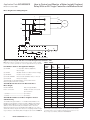
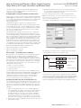
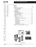
Application Data AP04209001E
Effective December 2008
How to Control and Monitor a
Motor Insight Overload Relay
With an ELC Logic Controller
via Modbus Serial
Application
Overview
The purpose of this application paper is to demonstrate how to control and monitor a Motor Insight
motor protection relay operating in conjunction
with a Freedom Series Contactor over Modbus
serial. Motor Insight includes a relay that works in
series with customer field wiring capable of energizing and de-energizing the contactor coil. Motor
Insight provides a high level of protection for the
motor and will not enable the contactor to be
closed if any condition exists that could damage
the motor. It will also open an energized contactor
should such a condition occur while the motor
is running.
Motor Insight is a motor protection relay that can
be used with any contactor. For this example, it
will be used with Eaton’s Freedom Series contactor. This application note will show how to wire
a Motor Insight with a Freedom Series contactor
to a motor and will also show how to connect
an ELC controller to a Motor Insight for control
and monitoring over Modbus. There are numerous data parameters that may be monitored from
Motor Insight, including: individual phase currents,
average of three phase currents, individual phase
voltages, average of three phase voltages, motor
power, voltage unbalance, current unbalance,
power factor, ground fault current, frequency,
thermal capacity and a fault queue. This
application example monitors all of these data
parameters with the ELC controller over Modbus.
This application example uses an ELC (Eaton Logic
Controller) to control and monitor Motor Insight
over Modbus serial, provided the customer
supplied field wiring is satisfied. The customer
supplied field wiring could be any contact interlock
that will remain open when a system requirement
to run the motor is not met. Any Modbus serial
master may be used for controlling/monitoring
Motor Insight.
Full control of Motor Insight is accomplished via
Modbus serial from the ELC controller and the
customer supplied field wiring. An ELC message
program is included with this application example.
This ladder logic program effectively sends a Read
message followed by a Write message continuously. If a fault occurs, the program will be notified
immediately. The program writes either a Reset
command to Motor Insight to close the contact or
a Trip command to open the contact. Note: The
Reset command will instruct Motor Insight to deenergize its internal relay, which in turn energizes
the contactor provided the customer supplied field
wiring is satisfied (see Figure 1). Sixteen different
parameters are being continuously monitored from
Motor Insight.
How to Control and Monitor a Motor Insight Overload
Relay With an ELC Logic Controller via Modbus Serial
Application Data AP04209001E
Effective December 2008
Motor Insight Power Wiring Diagram
MI
C
T1
L1
T2
C
Motor
L2
T3
C
L3
L1
L2
L3
L1
L2
&
&
&
H
O
A
NC
X
M
Start
Stop
95
X
2
96
3
M
Customer Supplied Wiring
Figure 1. Power Diagram with Customer Field Wiring Between Terminals 2 and 3
Note: When a Reset command is issued to Motor Insight, it will be enabled
to close the contactor, provided the customer supplied field wiring is satisfied.
Part Numbers Used for this Application Example
(1) C441BA
2 – 9 A; 200 – 240 Vac (50/60 Hz)
Motor Insight
Table 1. Values
Modbus
Register
Number
Modbus
Data
Address
Value
Description
400
399
0x00DD
Command Register: Relay OFF
399
0x00AA
Command Register: Reset/Energize Relay
(1) C441M
Modbus interface module for Motor Insight
400
(1) CN15DN3
Freedom Series Contactor
300
299
n/a
Phase A rms Current
(1) ELC-PC12NNDR
ELC Controller (Modbus master — Port 2)
301
300
n/a
Phase B rms Current
(1) ELC-PS01
ELC power supply
302
301
n/a
Phase C rms Current
Shielded cable for RS-485 Modbus connections between
Motor Insight and the ELC controller.
303
302
n/a
Average rms Current
304
303
n/a
Phase A rms Voltage (L1-L2)
Serial Modbus Connections from ELC Controller to
Motor Insight
305
304
n/a
Phase B rms Voltage (L1-L2)
306
305
n/a
Phase C rms Voltage (L1-L2)
307
306
n/a
Average rms Voltage
308
307
n/a
Motor Power (kW) Scaling x100
309
308
n/a
Voltage Unbalance %
310
309
n/a
Current Unbalance %
311
310
n/a
Power Factor
312
311
n/a
Ground Fault Current
313
312
n/a
Frequency
314
313
n/a
Motor Thermal Capacity
315
314
n/a
Fault Queue 1
ELC-PC12NNDR
Motor Insight Modbus
Port 2 connections
Modbus module connections
pin 1 Common
+ terminal ----------------------------------------- pin 2 Data +
- terminal ------------------------------------------ pin 4 Data -
Serial Modbus Addresses in Motor Insight for Control
and Monitoring
The Modbus Register address – 1 = Modbus Data Address. The
Modbus Control Register in Motor Insight is 400 decimal and the
Modbus Data Address for Control is therefore 399 decimal. The
address used is determined by the Modbus master. The ELC
Message Instructions use the Modbus Data Addresses to control
and monitor Motor Insight. The values for energizing and de-energizing a contactor controlled by Motor Insight are as follows in Table 1.
2
EATON CORPORATION www.eaton.com
Note: There are many additional parameters that can be monitored from
Motor Insight. Motor Insight may also be configured via serial Modbus
commands. Please refer to Chapter 8 Modbus Communications in the
Motor Insight User Manual, Publication MN04209001E.
How to Control and Monitor a Motor Insight Overload
Relay With an ELC Logic Controller via Modbus Serial
Application Data AP04209001E
Effective December 2008
The ELC message program included with this Application Note
writes one register to Motor Insight for control and reads the
16 parameters listed in Table 1.
3. Bit M1143 determines ASCII mode verses RTU mode for the
port. Set this bit for RTU mode and reset it for ASCII mode. RTU
mode must be used with Motor Insight.
Configuring Motor Insight for Modbus Communications
4. These settings must then be locked by setting bit M1120.
Please refer to the Motor Insight module’s User Manual, Publication
MN04209001E, for information on configuring Motor Insight for the
motor it will be protecting and other features. For this example, the
ELC controller’s Modbus port is configured for the following
interface parameters:
Note: All interface parameters, except the Station Number must be set the
same for all devices to properly communicate with each other. Each device
must have a unique Station Number.
An example of the RS-485 Protocol Screen is shown below.
19.2K baud, 8 bits/byte, 1 stop bit, even parity, RTU mode
Motor Insight Modbus module must be configured with the exact
same interface parameters, except the Modbus address. The ELC
is node 1 and Motor Insight is node 2 on Modbus, for this example.
The master on Modbus must support RTU mode. Motor Insight
does not support ASCII mode.
The Modbus interface parameters that need to be configured for
Motor Insight are located under the Operation parameters on the
unit. The Modbus Address is called the Device Address. The Baud
Rate is located under the Advanced section, parameter P.00. 8 bits/
byte, even parity and 1 stop bit are the defaults and do not need
to be changed for this example. If these three parameters need to
be modified, they may be modified via P.01 on the keypad or via a
Modbus command. Since Motor Insight only supports RTU mode,
only 8 bits/byte are allowed. The parity and number of stop bits may
be modified with a Modbus Write command (or P.01) to Modbus
Register 442 (Modbus Data Address 441) as follows:
Value of 0: Even Parity, 1 stop bit (default)
RS-485 Protocol Screen
Value of 1: Odd Parity, 1 stop bit
Value of 2: No Parity, 2 stop bits
Motor Insight — Communication Loss Behavior
By default, when a communication loss occurs, Motor Insight will
hold last state and not indicate a fault. The Modbus master’s
messages will time out indicating that communications is lost to
the device. P.04 is the “Comm Loss Behavior” parameter. However,
this feature must be enabled to be used. It cannot be enabled from
the keypad, but only with a Modbus command. If it is not enabled,
Motor Insight will Hold Last State on a communication loss. If it is
enabled, there are two choices:
The following logic can be used to configure the interface parameters for the ELC controller’s communication port 2:
M1002
MOV
H97
D1120
8 bits/byte, even parity,
1 stop bit, 19.2 Kbaud
MOV
K1
D1121
Station Number 1
SET
M1143
RTU Mode
SET
M1120
Lock Com2 Settings
First Scan Bit
1 = Fault on Comm Loss (Default)
2 = Hold Last State on a Comm Loss
To enable this feature:
Send a Modbus Write command with a value of 0x0088 to Motor
Insight’s Modbus Register Number 400 (Modbus Data Address 399).
This will enable Communication Loss behavior. The 0x0088 will
enable Motor Insight, by default, to report a fault and trip the
contactor should a loss of communications occur. The other
choice is Hold Last State on a Communication Loss.
Setting up the ELC Controller’s Communication Port
Figure 2. Logic Diagram
This same process can be used to configure the RS-232 communication port 1. Use D1036 instead of D1120 for the baud rate, parity,
stop bits and bits/byte. Select ASCII/RTU mode with bit M1139 and
Lock the Com1 settings with bit M1138. This is included in the
sample messaging program included with this application example.
The communication port for RS-485 communications is Port 2. It is
recommended to add logic to the program to configure the port at
first scan. To accomplish this, add the following to the control program (this is included in the program supplied with this application
example):
1. Under the Help pull down menu, select “Auxiliary Editing(C)”,
then “RS-485 Protocol Setting.” Select the interface parameters,
i.e., Baud Rate, Parity, Bits/Byte and Stop Bits. Then note the
hexadecimal value for your choices. For example, 8 bits/byte,
Even parity, 1 stop bit and 19.2K baud results in a hex value of
97. Add a MOV instruction to your program, to be executed at
first scan to move H97 (representing 97 Hex) to register D1120.
2. Assign a station number. MOV K# to register D1121, where the #
is the station number.
EATON CORPORATION www.eaton.com
3
Application Data AP04209001E
Effective December 2008
How to Control and Monitor a Motor Insight Overload
Reference Number Serial
Summary/Detailed Procedure
If the Modbus master is an ELC controller, the following procedure
should be straightforward. If another Modbus Master is used, be
sure it is properly configured and sends the same Modbus messages as the ELC controller in this example. The steps to getting
this application example working are as follows:
1. Configure Motor Insight’s interface parameters, per this
application example.
2. Make the RS-485 connections between the ELC controller
and Motor Insight’s Modbus module.
3. Load the ELC program supplied with this application example
to the ELC controller using ELCSoft.
Table 2. Supporting Documentation
Documentation
Reference Number
Manual
ELC System Manual
MN05003003E
Motor Insight User Manual
MN04209001E
Motor Insight Modbus Installation Leaflet
IL04209002E
Program Files
ELC Message Program
Motor_Insight.epc
In the event additional help is needed, please contact the Technical
Resource Center at 1-877-ETN-CARE.
4. Put the ELC controller into the Run Mode.
5. Go online with the ELC controller to view the
program execution.
6. Right click on the M20 contact and “Set On” the bit to Reset
Motor Insight and close the 95/96 Fault Relay contact.
7. Right click on the M21 contact in the program and “Set On”
the bit to Trip/Stop Motor Insight and open the 95/96 Fault
Relay contact.
8. View data addresses D500 through D515 to view the 16 data
parameters being monitored with this ELC program.
Eaton Corporation
Electrical Group
1000 Cherrington Parkway
Moon Township, PA 15108
United States
877-ETN-CARE (877-386-2273)
Eaton.com
© 2008 Eaton Corporation
All Rights Reserved
Printed in USA
Publication No. AP04209001E / Z7931
December 2008
PowerChain Management is a registered
trademark of Eaton Corporation.
All other trademarks are property of their
respective owners.