1
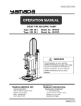
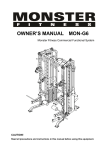
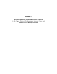
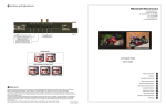
DHX Disposable Heat Exchanger User Manual
Thermo Fisher Scientific | 163 Research Lane, Millersburg, PA 17061 | +1-717-692-2104 | +1-800-724-4158 | www.asisus.com
ASI (A Part of Thermo Fisher Scientific) is an FDA Registered, ISO 13485:2003 Certified Manufacturer
MK-00382 | 04-16-15
DHX Disposable Heat Exchanger User MANUAL
Table of Contents
1.
General Description
1
2. Specifications
1
2.1 Dimensions and Weight
1
2.2 DHX Plate System
1
2.3 Single-Use Bag Assembly
1
3. Main Components
2
4. Safety Requirements
3
5.Installation3
5.1 Incoming Inspection
3
5.2 DHX Plate Installation
3
5.3 DHX Plate System Optional Configurations 5
6. Operation
6
6.1 Single-Use Bag Assembly Loading
6
6.2 Operation
9
6.3 Single-Use Bag Assembly Breakdown
10
7. Maintenance10
7.1 During Operation
10
10
7.2 Annually
8. Troubleshooting12
9. Warranty Information
12
10. Recommended Parts
13
11.
Contact Information
14
DHX Disposable Heat Exchanger User MANUAL
1. General Information
The DHX Single-Use Heat Exchanger is a modular system where stainless steel dimpled plates are used in conjunction
with a single-use bag assembly to provide heat transfer. The DHX assembly consists of a series of removable stainless
steel plates that are dimpled and seam welded internally to form a serpentine pattern. The plates are connected with a
series of hoses.
The serpentine pattern on the stainless steel plate system matches the serpentine pattern on the single-use bag
assembly. The single-use bags are manifolded together with disposable tubing. Heat transfer fluid is intended to
flow through the plate system counter-current to the process fluid flowing within the single-use bag assembly.
The temperature differential of the heat transfer fluid and the counter-current flow patterns provide efficient heat
transfer to the process fluid within the single-use bag assembly.
2. Specifications
2.1. Dimensions and Weight
Height:
27” (68.6 cm)
Width:
20” (50.8 cm)
Depth:
29” (73.7 cm)
Dry Weight:
331 lbs (150 Kg)
Full Weight (with 4-Bag Assembly):
419 lbs (190 Kg)
2.2. DHX Plate System
Number of Plates:
5
Effective Heat Transfer Area:
Up to 27 sq ft.
Material of Construction:
316L SS
Pressure / Temperature Rating:
FV/140 PSIG @ 150°F (Standard)
Code Stamp:
ASME U-1 (Standard- Each plate individually stamped)
2.3. Single-Use Bag Assembly
Number of Bags:
Up to 4
Bag Material of Construction:
Low Density Polyethylene
Pressure / Temperature Rating:
20 psig @ 122°F (50°C)
DH X Dis p os ab le H e at E xchanger
1
DHX Disposable Heat Exchanger User MANUAL
3. Main Components
Tabs Hold Bag in Place
Plate System Hinges (6 total)
Fixed Insulation on Each End Plate
Single-Use Tubing
Connects Bag Assemblies
High Point Vent Valves
Wing Nut (6 total)
Fanning Lever
Locking Lever
Flexible Hoses Connect
Plate System
Cart Base
Clean Room
Grade Casters
4. Safety Requirements
4.1. The appropriate safety devices must be integrated as outlined in the installation section (Pages 3-5) in order to
prevent the over-pressurization of the DHX plate system.
4.2. National as well as local codes and standards must be followed for pressure vessels as it applies to the DHX
plate system.
4.3. Instrumentation and automated interlocks are recommended to prevent over-pressurization and/or rupture of
the single-use bag assembly as outlined in the installation section (Pages 3-5).
4.4. The six (6) DHX plate system hinges with wing nuts must always be firmly secured during operation. Failure to install and tighten all of the six (6) hinges properly poses an operator safety risk and may cause mechanical damage.
4.5. The DHX safety lever must always be used when opening and closing the plate system to avoid pinch point hazards.
4.6. Failure to follow ASI’s installation and operation instructions may affect the DHX performance and overall functionality.
4.7. It is the user’s responsibility to maintain the DHX for optimal performance.
2
w w w. a s i s u s . c o m
DHX Disposable Heat Exchanger User MANUAL
5. Installation
Perform the following steps to initially install the DHX:
5.1. Incoming Inspection
5.1.1. Carefully uncrate the DHX.
5.1.2. Thoroughly review the product for damage.
5.1.3. Check the product and components against the parts list (Section 10.1).
5.1.4. If the product is damaged or if the shipment is not complete, please contact ASI Customer
Care immediately.
ASI Customer Care
163 Research Lane
Millersburg, PA 17061
717-692-2104 or 800-724-4158
5.2. DHX System Installation
5.2.1. Unlock all four (4) casters and transport the DHX to the desired location.
5.2.2. Ensure the DHX is on a level surface and lock the casters in place.
5.2.3. The recommended installation setup for the DHX system is shown in diagram below.
See 5.3.3.2 Note: It is recommended that any unused plates be capped or sealed appropriately.
TIC
**
TIT
TE
I
PROCESS INLET
TE
*
PSV
PI
FE
PI
PROCESS OUTLET
STR
HTF SUPPLY (PUMP OR TCU)
PI
HTF OUTLET
* High pressure interlock recommended to shut down pumps or flow source.
** Temperature control loop recommended for heating and high temperature applications. May not be required for cooling applications.
DH X Dis p os ab le H e at E xchanger
3
DHX Disposable Heat Exchanger User MANUAL
5. Installation (Continued)
5.2.4. The DHX inlet and outlet connections are ½” compression fittings as standard. It is highly recommended
that a strainer be used upstream of the DHX plate system if the heat transfer fluid may contain debris.
Any debris that collects within the DHX will restrict flow and affect performance.
5.2.5. Connect the heat transfer fluid inlet and outlet connections as shown below.
HTF INLET
HTF OUTLET
5.2.6. The DHX plate system operates independently of the single-use bag assembly. The installation of a
single-use bag assembly is not required during the initial priming of the plate system.
5.2.7. Ensure all of the hoses are connected securely to each plate and the high point vent valves are closed.
5.2.8. Ensure the plate system is closed using the locking and fanning levers . 5.2.9. Ensure the six (6) DHX plate system hinges are secure. Ensure the bolts are sitting in the recessed
section of the plate tab and the six (6) wing nuts are firmly hand tightened.
5.2.10. Open the heat transfer circuit to the DHX.
Note: It is normal to hear some “knocking” as the plate system initially pushes the air through the plates.
5.2.11. Bleed off the air in each plate using the high point bleed valves and a small container to collect any
released heat transfer fluid. The bleeding steps should be repeated until all the air is expelled from
the DHX plate system.
4
5.2.12. Once the DHX plate system is bled, it is ready for operation.
w w w. a s i s u s . c o m
DHX Disposable Heat Exchanger User MANUAL
5. Installation (Continued)
5.3. DHX Plate System Optional Configurations
5.3.1.
The DHX system is a modular and changeable system
in which 1-3 bag assembly can be used. All five (5) plates
are not required at one time. If either a 1-3 bag assembly
is used, there are two options in setting up the DHX
plate system.
5.3.2. Option 1 – Insulation foam between the unused plates
5.3.2.1.
Insulation
Foam Spacers
The heat transfer fluid may run through all five
plates with 1-3 bag assembly. Flexible insulation foam spacers are provided by ASI and inserted
between every unused plate after the bags have
been installed. These insulation foam spacers
must be used to prevent damage or warping
to the plates.
5.3.3. Option 2 – Bypassing the unused DHX Plates
5.3.3.1.
The unused plates in the DHX system may be
disconnected per the example to the right.
Insulation foam spacers must be inserted
between every unused plate to prevent
damage or warping.
Insulation
Foam Spacers
5.3.3.2. The installation and bleeding instructions
in section 5.2 must be followed accordingly
for the plates in use if Option 2 is chosen.
Any unused plates should be capped or
sealed appropriately.
Disconnected
DHX Plates
DH X Dis p os ab le H e at E xchanger
5
DHX Disposable Heat Exchanger User MANUAL
6. Operation
6.1. Single-Use Bag Assembly loading
NOTE: Ensure all four (4) casters are in the locked position (down) before loading the bag assembly into the DHX.
6.1.1. Isolate the heat transfer fluid circuit to stop the heat transfer circuit from flowing through the DHX
plate system. It is acceptable to have the plates pressurized with heat transfer fluid during the bag loading.
6.1.2. Remove the wing nuts and bolts from the six (6) DHX plate system hinges in the order shown in the
diagram below. NOTE: It is a good practice to have a free hand under the wing nut during its removal to
prevent it from dropping to the floor.
1
3
4
6
5
6.1.3.
2
Once the bolts are removed, the DHX will open slightly and relax against the locking mechanism. Use the
safety levers to fan out the plates; this can be done by pulling the locking lever (located towards the
bottom, closest to the heat transfer fluid ports) slightly to release the locking mechanism (As shown in step 1). Then using the upper fanning lever, move it towards the locking lever with control to fan out the DHX plates (As shown in step 2).Remove the insulation foam spacers (if applicable). The DHX is now in the open position and the single-use bag assembly can be placed.
Fanning Lever
Locking Lever
Step 1: Pull on the Locking Lever.
6
w w w. a s i s u s . c o m
Fanning Lever
Step 2: Move Fanning Lever towards the Locking Lever.
Locking Lever
DHX is in the Open Position.
DHX Disposable Heat Exchanger User MANUAL
6.1.4.
Note there are tabs to secure each bag to the corresponding plate on the top and bottom of the single-use bag. For ease of installation, all tabs should be separated prior placing the bags between the plates. Insert each bag used in the 1-4 single-use bag assembly within each corresponding plate. Ensure the tubing is cascading from one bag to the next (Reference section 5.3 to view the two different configuration options
if using less than all five (5) plates). Attach the bottom tabs of each bag first.
NOTE: Pressing the stud through the slit at the bottom is made easier by alternately tugging up at the top of
the bag with one hand and pushing down at the tab area with the other.
Once the bags are secure at the bottom, engage each set of top tabs. Remove and discard any loose pieces from the tabs after they are in place.
6.1.5. The process flow must always be set up, so the process fluid fills from the bottom of the bag to the top
of the bag to displace any air throughout the single-use bag assembly.
6.1.6.
For DHX bag assemblies with drain ports (DX00010-I – DX00013-I) ensure that the drain port is connected to the proper drain connection in the process. Close the pinch clamps on each drain line before starting
the process fluid flow.
DH X Dis p os ab le H e at E xchanger
7
DHX Disposable Heat Exchanger User MANUAL
6. Operation (Continued)
6.1.7. The process must be set up for counter-current flow where the process fluid enters from the opposite side of the heat transfer fluid in order to provide the most efficient heat transfer method. The process fluid
should cascade through each bag in the series in the opposite direction of the heat transfer fluid path.
6.1.8. There must always be positive pressure on the process inlet side of the DHX for proper functionality.
Process Fluid
Heating / Cooling Fluid
6.1.9. Connect the inlet and outlet of the single-use bag assembly to the upstream and downstream process connections with the DAC’s, tube welds, or connections specified for the user’s custom bag assembly.
6.1.10. If the optional single-use bag assembly with low point drains are used, the low point drain connections are manifolded together.
6.1.11. The single-use flow path tubing left in its natural state could be trapped between the braided heat
transfer hoses when the DHX unit is being closed. To prevent this, rest the single-use flow path tubing across the top of the heat transfer hose assemblies. Ensure that both hands and the flow path tubing are clear from the plate system while closing the DHX unit using the fanning lever and engaging the lock, and reinstalling the hinge bolts.
Flow Path Tubing in Natural State - Incorrect
8
w w w. a s i s u s . c o m
Flow Path Tubing Placed Correctly
DHX Disposable Heat Exchanger User MANUAL
6. Operation (Continued)
6.1.14. Re-install the hinge bolts one at a time in the order shown in the diagram below. Place all of the bolts
before fully tightening them and ensure that each bolt is recessed in the plate tab appropriately. It is good practice to check the tightness of the side bolts after tightening the top bolts and vice a versa.
NOTE: It may be necessary to pull on the fanning lever while installing the hinge bolts to assist the process.
6
6.2.
5
4
3
2
1
Operation
6.2.1.
Once the fluid connections are made, start the processing by resuming the heat transfer fluid circuit. The
flow of the heat transfer fluid can be initiated up to 15 LPM. The bleed valves at the top of each plate can
be used to vent any trapped air. A piece of tubing should be used to direct any fluid that may exit the
valves to a waste receptacle.
6.2.2. Start the process flow slowly, starting at 3 LPM (or less). The bags fill from the bottom to top displacing
the air as the process fluid cascades through the assembly.
6.2.3. Carefully monitor the bag assembly during the priming step to ensure there are no leaks, the tubing is not
pinched, and all air is being displaced accordingly.
6.2.4. Once the bag assembly is primed, the desired flow rate may be set and the process can run continuously.
Anytime the flow is stopped while in operation, it is recommended to slowly ramp up the pump when
the flow is resumed. This recommendation is especially the case for high flow rate applications in order to prevent pressure surges in the single-use bag assembly.
DH X Dis p os ab le H e at E xchanger
9
DHX Disposable Heat Exchanger User MANUAL
6.3. Single-use Bag Assembly Breakdown
6.3.1. Once the process operation is complete, the single-use bag assembly should be depressurized and drained
to the extent possible prior to removal from the DHX plate system.
6.3.2. After the bags have been partially drained, and the bags are no longer pressurized, remove the wing nuts
and bolts from each of the six (6) DHX plate system hinges.
6.3.3. Open the DHX plate system using the safety levers (Section 6.1.3).
6.3.4. Release the bottom and top tabs on all the bags and remove the single-use bag assembly.
6.3.5. If gross recovery of the process fluid is desired, start with the bag at the process inlet, remove the bag tabs
from the corresponding connection points on the plate and gently lift and tilt the bag toward the drain
lines. Once the first bag is nearly drained, repeat the process with the consecutive bags until the last bag
in the assembly has been drained.
6.3.6. If the single-use bag assembly with low point drains was used, any remaining process fluid may be
recovered through the process inlet by reversing the pump, or through the low point drain manifold outlet.
To use the process inlet, the process outlet and low point drain manifold outlet tubing should be closed using a clamp. Open the pinch clamps on each individual drain line before starting the process fluid flow. The process fluid can be recovered by reversing the pump and routing the process fluid to an
appropriate collection container. Alternately, to use the low point drain manifold outlet, the process inlet
and outlet tubing of the bag assembly should be closed using a clamp and the low point drain manifold
outlet tubing can be routed to a pump so the process fluid may be recovered. Open the clamps on each
individual drain line before starting the process fluid flow.
6.3.7. Discard the assembly in the appropriate waste stream as dictated by the end user’s requirements.
7. Maintenance
Following is a basic list of maintenance items to be performed at varying intervals.
7.1.
Routine Maintenance
7.1.1. Routinely inspect the plate system for rouge, pitting or signs of corrosion. De-rouge and/or passivate the
plate system accordingly.
7.1.2. If applicable, inspect and clean the strainer upstream of the plate system routinely to ensure the target
heat transfer fluid flow rate is maintained.
7.2.
Preventative Maintenance*
7.2.1. Remove the hoses and inspect the plate inlet/outlet connections for signs of debris. If signs of debris are
evident or if it is suspected that debris has settled in the bottom of the plates, clean and flush the DHX
plate system accordingly.
7.2.2. Inspect the DHX plate system hoses for any signs of kinking or excessive wear. Replace hoses as necessary.
7.2.3. Inspect the bleed valves to ensure proper performance. Replace bleed valves as necessary.
* Note: It is recommended that the preventative maintenance procedures are completed on an annual basis for systems
in regular use. Hoses are recommended to be replaced at least every two years. Preventative maintenance intervals
may be revised at the discretion of the end user based on system use and service.
10
w w w. a s i s u s . c o m
DHX Disposable Heat Exchanger User MANUAL
8. troubleshooting
The following table lists possible situations that may occur during operation of the DHX and courses of action to pursue to
correct them.
Problem
Probable Causes
Solutions
Process fluid is not
reaching the desired
temperature at the
DHX outlet.
DHX system is set up incorrectly.
1. Ensure the system is set up per Figures on pages 2 and 3.
2. Ensure the heat transfer inlet connection is at the top of each
plate. The hose at the heat transfer outlet connection at the
bottom of each plate and should be connected with a hose to the
inlet connection at the top of the next plate in series.
3. Ensure the single-use bag assembly is set up to flow in the
opposite direction (counter-currently) to the DHX plate system.
The process fluid should enter the system from the opposite side
as the heat transfer fluid. The bags should flow from bottom to
top where the single-use tubing at the top of the bag should
connect to the bottom of the next bag in series.
Lack of positive pressure on
bag assembly.
1. Ensure there is sufficient pressure so the single-use bags fit
tightly within each plate.
2. Ensure there is a source to apply positive pressure upstream of
the DHX system. See Figure on page 3.
Heat transfer fluid flow rate is
too low.
1. Verify heat transfer fluid flow rate.
2. Ensure the hoses, plate system connections and plate system
is not clogged with debris. If applicable, ensure the strainer
is clean.
3. Ensure the DHX plate system hoses are not kinked.
Process fluid flow rate is not at
set point.
1. Verify the process fluid flow rate.
Single-use bag assembly have
improper fit up.
1. Inspect the single-use bags to ensure the bottom and top tabs
are secure.
2. Ensure the single-use bag assembly hoses are not kinked or
pinched between the DHX plate system hoses.
2. Inspect the fit up of each single-use bag to ensure the serpentine
pattern matches the corresponding DHX.
DHX plate system contains
pockets of air.
1. Ensure DHX system is on a relatively flat surface and bleed valves
are at the high point.
2. Bleed any residual air from the DHX Plate system using the high
point bleed valves.
Lack of sufficient insulation.
1. If all plates are not in use, reference section 5.3, ensure flexible
insulation is installed on the outer side of the last plate in series.
DHX palte system has exceeded
the heat transfer capacity.
1. Verify the process and heat transfer fluid flow rates align with the
DHX sizing calculations. Contact ASI for support as necessary.
DH X Dis p os ab le H e at E xchanger
11
DHX Disposable Heat Exchanger User MANUAL
8. Troubleshooting (Continued)
Problem
Probable Causes
DHX plate system and/or
plate system hinges
are becoming warped as
single-use assemblies are
filled or during normal
operation.
DHX plate system supports are 1. Ensure the all six (6) DHX support bolts are sitting securely in the
installed incorrectly.
recessed grooves.
Single-use bag assembly has
exceeded its pressure rating.
Solutions
1. Ensure the pressure on the single-use bag assembly does not
exceed 20 psig at 50°C. Note: High pressure interlocks are highly
recommended per Figure on page 3.
2. Ensure there are no pressure surges during initiation of
process flow
Single-Use Flow paths are
trapped between the heat
transfer hoses
DHX plate system has
exceeded its pressure rating.
1. Ensure the heat transfer fluid pressure does not exceed the
pressure rating of the DHX plate system. Note: A pressure safety
valve is highly recommended per Figure on page 3.
The flow paths were not
placed on top of the heat
transfer hoses before closing
the DHX
1. Before Fluid is introduced, remove the bolts (as instructed in
section 6.1.7) and re-open the DHX. Follow the instructions in
section 6.1 to properly align the flow path tubing.
9. Warranty Information
The DHX from ASI is covered under a 1 Year Limited Warranty.
ASI will not be liable under any warranty expressed or implied in any amount greater than the price of the product sold.
12
w w w. a s i s u s . c o m
DHX Disposable Heat Exchanger User MANUAL
10. Recommended Parts
To ensure there is the minimum amount of machine downtime, ASI recommends that the following items be maintained
(minimum quantity) in the manufacturing facility spare parts inventory. Contact ASI for spare parts. Other parts may be
replaced if needed.
A
10.1.
Parts List
Position
Description
Part Numbers
Model: DHX-1000
Model: DHX-1001
Recommended Spares
N/A
Disposable Heat Exchanger Assembly
30-DHX-1000
30-DHX-1013
A
DHX Cart Base
30-DHX-1001
30-DHX-1014
N/A
B
HTF Inlet Insulated Plate
30-DHX-1002
30-DHX-1015
N/A
C
HTF Outlet Insulated Plate
30-DHX-1003
30-DHX-1016
N/A
D
Inside Plate
30-DHX-1004
30-DHX-1017
N/A
E
Inside Mid A Plate
30-DHX-1022
30-DHX-1018
N/A
F
Inside Mid B Plate
30-DHX-1023
30-DHX-1019
N/A
G
Safety Lever
30-DHX-1005
30-DHX-1020
N/A
H
Locking Caster
30-DHX-1006
30-DHX-1006
N/A
I
High Point Bleed Valve
30-DHX-1007
30-DHX-1007
2
J
DHX Plate Hose Ass'y
30-DHX-1008
30-DHX-1008
2
K
DHX Support Bolt
30-DHX-1009
30-DHX-1009
2
L
DHX Support Wingnut
30-DHX-1010
30-DHX-1010
2
M
Hinge Pin
30-DHX-1011
30-DHX-1011
N/A
N/A
Flexible Insulation Insert
30-DHX-1012
30-DHX-1012
1 (If applicable)
DH X Dis p os ab le H e at E xchanger
13
DHX Disposable Heat Exchanger User MANUAL
11. Contact Information
Customer Care
Your ASI equipment has been designed to provide you with years of reliable and dependable performance. To ensure that
you maintain maximum performance over the years, we offer a complete package of customer services, including:
•
Original Quality Replacement Parts
•
Factory Repair Service
•
Field Service
•
Process Application Assistance
•
Preventive Maintenance Programs
•
Training Programs
ASI maintains complete manufacturing records of all ASI equipment and will repair your unit to meet the original
specifications. If required, units can be updated to the very latest technologies in materials and design.
We wish you much success with your new ASI equipment and thank you for your confidence in our equipment. The entire
ASI Corporate Team is here for one purpose, and that is to make sure you obtain maximum results from our equipment.
If you need assistance, please call immediately.
ASI Customer Care Department
163 Research Lane
Millersburg, PA 17061
+1-717-692-2104 [email protected]
14
w w w. a s i s u s . c o m