1
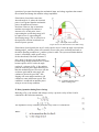
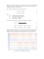
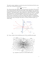
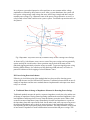
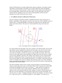
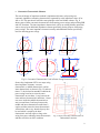
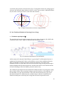
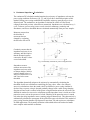
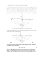
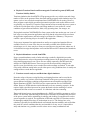
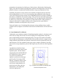
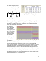
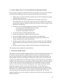
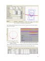
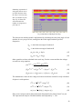
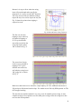
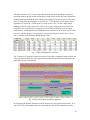
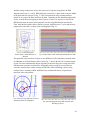
Realistic Testing of Power Swing Blocking and Out-of-Step Tripping Functions
Q. Verzosa, Jr. “Jun”
Doble Engineering Company
Abstract
Sudden changes in the power system, such as faults, network changes due to line trip outs,
and disconnection of a large load or of a generating plant, forces the remaining generators
to adjust and settle to new stable conditions. In some cases the swings are so large that some
generators run out of step and lose synchronism. With generators having different
frequencies these power swings result in voltages and currents in different parts of the
networks to swing in amplitude and phase angle. The impedance measurements based on
these varying voltages and currents will also oscillate. If the measured impedance becomes
very small and enters the distance relay zones it can lead to an undesired trip of the distance
relay. Distance relays have power swing blocking features to detect these conditions and
prevent a misoperation for stable power swings. However, during the blocking period a fault
can occur on the line and the distance relay must detect this condition and unblock the
distance zones.
For severe power swings and out-of- step conditions, it may be desirable to trip on certain
transmission lines to separate parts of the system into sub-grids that will eventually settle at
stable states, instead of a total system collapse, and also making it easier to restore the power
system. An out-of-step tripping function can be implemented as a standalone relay or added
as another function in a distance relay to detect these conditions and perform a controlled
trip the transmission line.
The traditional approaches for swing and out-of-step detection include parallel single or
double blinders on each side of the line angle, concentric impedance elements which may be
of circular shape or quadrilateral shape, with a timer to measure the impedance trajectory
time from when the outer element detects the power swing until the time that the inner
element detects the swing. If the time is longer than the set time the power swing blocking
function will block distance elements from undesired tripping, whereas it will not block for
faults. More recent methods of detecting these conditions include continuous rate-of-change
of impedance, swing-center voltage, and superimposed current.
Testing relays that employ these different methods of detection is a challenge. Traditional
state simulation testing methods to simulate specific points in the impedance plane may work
for the traditional detection schemes but will not work for the more recent power swing
detection schemes. A transient playback of recorded power swings, or transient files from
EMTP and stability programs provide a realistic test but require highly specialized
personnel, and it is difficult to target the impedance zones to test. An easier way of simulating
realistic waveforms has been developed that can test all types of power swing and out-of-step
detection schemes.
This paper covers the basics of power swing and out-of-step phenomena and the various
schemes of detecting these conditions, and ways of testing the power swing blocking and outof-step tripping functions.
1
I. Basic Power System Stability and Power Swing Phenomena
Power systems under normal system conditions are operated very close to their nominal
frequency of 60 Hz or 50 Hz with very small deviations in the order of 0.02 Hz for larger
systems to 0.05 Hz for much smaller systems. Under these steady-state conditions power
generation and load are balanced.
Fig.1. Two-Machine System Model
Considering the classical two-machine system model shown in Fig. 1, the power transmitted
can be represented by the equation:
|
|·|
|
|
|
· sin
(1)
Where:
- is the voltage of machine S
- is the voltage of machine R
- is the angle by which leads
=
- is the rotor angle of machine S
- is the rotor angle of machine R
- is the total impedance between the two machines consisting of
,
, and
- is the impedance of source S
- is the impedance of source R
- is the impedance of the transmission line
The power angle curve shown in Fig. 2 graphically
describes the power relationship between the power
transmitted and the angle between the two ends. It
shows that the power transfer increases with
increasing angle δ from 0° to 90° and then decreases
beyond 90°. Systems are normally operated well
below the maximum power transfer at 90°, the
maximum power transfer angle, at some power P0
corresponding to an angle δ0. The maximum power
is:
| |·| |
(2)
| |
Fig. 2. The Power Angle Curve
If a large disturbance occurs, such as a fault on the line, the power transmitted is suddenly
reduced (the electrical output during the fault is represented by the lower curve in Fig. 3) and
the electrical output of machine S decreases to PF. However, the input power P0, equivalent to
the mechanical torque applied to the generator cannot instantly decrease, and this imbalance
causes the machine rotor to accelerate and the angle δ increases. This analysis neglects the
2
operation of governors that change the mechanical input, and voltage regulators that control
the excitation and change the machine voltage amplitudes.
If the fault is cleared after some time
when the angle is δc, where the electrical
power is now greater than the mechanical
power, the machine will start to
decelerate. However, due to inertia the
machine rotor angle will continue to
increase to δe. At this point, Area 1,
representing the accelerating energy will
be equal to Area 2, representing the
decelerating energy. This is referred to as
the equal-area criterion in textbooks on
electrical power systems.
Fig. 3. The Equal-Area Criterion
(Figure shows a fast fault clearance and a stable swing)
If the fault is cleared quickly the Area 2 can be equal to Area 1 before the angle can reach the
limiting angle δL and the system will eventually recover after some oscillation and settle at
the initial operating condition at δ0, and the system is stable. The system oscillation that that
occurs is considered a stable power swing.
On the other hand, if the fault clearance is
slow, angle δC advances too far that Area 1
becomes large enough such that Area 2 cannot
become equal to Area 1 before the angle
reaches δL, as shown in Fig. 4. Beyond this
point the electrical power again becomes less
than the mechanical power, the rotor will now
accelerate again and the rotor angle will
continue to increase beyond 180°. Pole
slipping will occur and the machines will
continue to rotate at different speeds. This
Fig. 4. Unstable System due to
condition is considered an unstable power
Slow Clearing Time
swing or an out-of-step condition.
II. Relay Quantities during Power Swings
Referring to Fig.1, the currents and voltages seen by a protective relay at Bus S can be
calculated by the following equations:
The impedance seen by a distance protective relay at bus S is calculated as:
Where:
3
During power swings the frequencies of the two machines, fS and fR, become unequal and the
instantaneous values of the voltages and currents have to be calculated considering the time
varying rotor phase angles of both machines.
The rotor angle of machines S and R at any point in time are:
2
(6)
2
(7)
Where:
- is the initial rotor angle of machine S
- is the initial rotor angle of machine R
- is the frequency of machine S
- is the frequency of machine R
The currents and voltages at bus S and bus R are calculated by the formulas:
| |
|
|
|
|
|
|
(8)
|
| |
|
|
| |
·| |
|
|
|
| |
·|
|
(9)
(10)
The above formulas are for phase A. Power swings are generally three-phase phenomena and
the phase B and Phase C quantities are 120° away from phase A. Fig. 5 shows a plot of the
voltages and currents at Bus S during an unstable power swing or out-of-step condition.
Fig. 5 Voltage and Current Waveforms at Bus S
4
The positive-sequence impedance seen by the relay at bus S in the direction of the line at any
point is time is calculated by the equation:
|
|
| |
(11)
Fig. 6 shows the plot of the impedance locus seen by a distance relay at Bus S. The trajectory
of the swing locus depends on the ratio of the machine voltage amplitudes (ES/ER) and where
the system electrical center is located. The electrical center is the midpoint of the total system
impedance ZT. When both machine voltages amplitudes are equal the swing locus is a straight
line perpendicular to ZT and passing through the electrical center, where δ=180°. A point on
this line where δ=90° is also shown. When ES is larger than ER the impedance trajectory
follows a large circle that passes just above the electrical center. When ES is smaller than ER
the trajectory is a circle below the electrical center. When the frequency fS is larger that fR the
direction of the swing is from right to left, whereas, it will move from left to right is fS is
smaller than fR.
Fig. 6 Impedance Trajectories Seen By a Distance Relay at Bus S
Fig. 7 shows a family of circles for different ratios of |ES/ER| and different slip angles.
Fig.7. Impedance Trajectories for Various Ratios of |ES/ER|
5
In a real power system the frequencies of the machines are not constant and the voltage
amplitudes are dictated by other factors as well. After a system disturbance the system will
have power swings mostly small swings, but some will be large enough and others may be
unstable power swings. Fig. 8 illustrates some of the power swing trajectories as seen by a
relay located on bus S that could occur in a power system. Two distance protection zones are
also plotted.
Fig. 8 Impedance Trajectories Seen By a Distance Relay at Bus S during Power Swings
As shown in Fig. 8 the distance zones can see some of the power swings and can potentially
operate and trip the circuit breaker. Some operations may be desired but many will be
undesired tripping particularly when the swings are stable. To prevent tripping power swing
blocking (PSB) schemes, also called out-of-step blocking (OSB) schemes, are used to in
protection schemes to block tripping of selected distance zones
.
III. Power Swing Detection Schemes
Following is a brief discussion of the methods that have been used for detecting power
swings and schemes used for OSB and OST functions. Traditional schemes based on rate-ofchange of impedance and the newer methods that are implemented in microprocessor-based
relays, are covered.
A. Traditional Rate-of-change of Impedance Schemes for Detecting Power Swings
Traditional methods measure the positive-sequence impedance seen by the relay and the rateof-change of impedance. During normal operating conditions the measured impedance is the
load impedance and that point is far away from the distance protection zones. When a fault
occurs the measured impedance jumps immediately from the load impedance to a point on
the impedance plane that represents the fault. On the other hand, when a power swing occurs
the measured impedance moves slowly at some trajectory in the impedance plane and at a
rate depending on the slip frequency between the machines. This large difference in the speed
of movement of impedance in used to differentiate between faults and power swings. This
6
method of differentiation is usually implemented using two impedance measuring elements
separated by some impedance ΔZ and the use of a timer. When the measured impedance
crosses one element it starts the timer. A fault is declared if the swing crosses and operates
the second impedance element before the timer expires. On the other hand, if the timer
expires before the impedance locus crosses the second impedance element, then the
impedance movement is declared a power swing.
a. Two-Blinder Scheme for PSB and OST Functions
The rate-of-change of impedance method is implemented in many relays using a pair of
blinders, separated by some impedance value ΔZ, and a timer tOSB. The two-blinder scheme is
shown in Fig. 9. Two parallel blinders are placed to the right of the line impedance and
another pair on the left side. The timer tOSB is started when the swing crosses the outer
blinder.
Fig. 9 Two-Blinder Power Swing Detection Scheme
For a fault condition the impedance locus moves quickly to the fault impedance point and the
inner blinder operates immediately well before the time expires. In case of a power swing,
with a slower movement of the impedance locus, tOSB will expire before the swing locus
crosses the inner blinder, in which case a power swing condition is declared. If the swing
locus enters the region between the two blinders and stays there before the timer tOSB expires,
a power swing condition is declared. This scheme can be used for a power swing blocking
function to and block the distance relay protection zones from tripping in case the swing
locus proceeds further into zone operating characteristic. A reset timer, started when the PSB
asserts, is normally used to force it to deassert when the timer expires even if the impedance
locus stays inside the inner blinders. Another timer may also be used delay resetting when the
swing locus exits the outer blinder.
The same two-blinder scheme can be used for out-of-step tripping, except that the timer tOST
setting is usually shorter than when used for PSB. When a power swing occurs and the locus
crosses the outer blinder the timer starts; if the timer tOST expires before the swing locus
crosses the inner blinder a power swing situation is detected. If the swing continues its
trajectory and crosses the inner blinder an OST condition is declared. The OST function can
either be set to trip immediately or wait until the swing locus leaves the inner blinder, and
after the timer tOST expires. Tripping immediately when the inner blinder is crossed is referred
to as “trip on the way in” or “predictive tripping” or “early tripping”. The other case is
7
referred to as “trip on the way out” or “delayed tripping”. In some applications tripping is
allowed only when pole slipping occurs after a set number of times.
If the circuit breaker is not rated for out-of-phase tripping, early tripping when the slip angle
is approaching 180°could damage the breaker. In this case tripping on the way out is used and
an additional time may be used so that tripping will occur only when the slip angle is
approaching zero degrees. If the application calls for very fast tripping before the swing
develops into a full out-of-step condition where voltage is further depressed, early tripping is
used but one must be certain that the circuit breaker will be capable of safely tripping on outof-phase conditions.
In some applications both OSB and OST function are required. The two-blinder scheme can
be use for both OSB and OST functions in the same relay. Some system disturbances produce
power swings that are slower and stable while other more severe disturbances can cause
unstable and out-of-step conditions with an impedance trajectory that move much faster. This
difference in speed between these conditions can be used to identify if a power swing is
stable or unstable. Two timers are used, one timer tOSB with a longer setting is used for
identifying stable swings, and another timer tOST is used for identifying unstable swings.
When the power swing impedance locus crosses the outer blinder both timers tOSB and tOST
are started. If the swing locus crosses the inner blinder before both timers expire, a fault is
identified, and no OSB or OST occur. If only tOST expires and not tOSB before the inner
blinder is crossed an unstable power swing condition is declared and OST is asserted. If the
swing is slow both timers expire before the inner blinder operates and the swing is deemed to
be stable and only OSB is asserted.
b. Single-Blinder Scheme of OST Function
The single-blinder detection scheme is
shown in Fig. 10 and can be used for
detecting unstable power swing or outof- step conditions. It requires
additional logic to determine the
direction from where the swing entered
and where it left. When a power swing
impedance locus crosses one blinder
from one side a timer is started. If it
stays between the two blinders and the
timer expires the locus later crosses the
other blinder going in the opposite
direction from where it entered, an outof-step condition is declared.
Fig. 10 Single-Blinder Scheme Used for
Out-of-step Tripping Function
The single-blinder scheme cannot be used for OSB function to block a distance relay for
stable power swings because the impedance locus has to cross the two blinders on both sides
of the line. As in the case of the two-blinder scheme tripping can be delayed to allow the slip
angle be reduced before tripping the circuit breaker. Tripping only after a certain number of
pole slips can also be implemented.
8
c. Concentric Characteristic Schemes
The rate-of-change of impedance method is implemented in many relays using two
concentric impedance measuring characteristics separated by some impedance value, ΔZ or
ΔR, or ΔX. The operation is based the same principle as the two-blinder scheme. Fig. 11
shows some of these concentric characteristics for detecting power swings and providing PSB
and OST functions. The inner impedance characteristic can be an existing distance protection
zone or it may be an additional impedance element specifically for the purpose of detecting
power swings. The outer impedance element is usually and additional element specifically
used for detecting power swings.
Fig. 11 Concentric Characteristics Used in Power Swing Detection Schemes
Some relays implement OST in two steps using
three impedance elements - an outer
characteristic, a middle characteristic, and an
inner characteristic as shown in Fig. 12, and two
timers. To be declared an unstable condition the
power swing locus has to enter the outer
characteristic to start timer 1, stay between the
outer and inner characteristic until timer 1 times
out, move inside the middle characteristic to
start a second timer 2 and stays between the
middle and inner characteristics until timer 2
expires and then enters the inner characteristic.
A third timer with a very short delay may also
be used which is stated by the inner
characteristic and will expire as long as the
swing locus stays within the inner characteristic
and then will assert an OST condition.
Fig. 12 Triple Concentric Characteristics for
PSB and OST functions
9
A variation of this scheme is shown below in Fig. 13 using mho elements; the setting angle of
each zone will affect the shape whether it will be a circles, lens or tomato. Additional blinders
may be used to restrict the resistive reach of the mho elements.
Fig. 13 Triple Characteristics for Power Swing Detection
B. Non-Traditional Methods for Detecting Power Swings
a. Continuous superimposed ΔI
The superimposed current method compares the present values of currents with a buffer that
is taken two cycles earlier. Figure 14 illustrates how the method works.
Fig. 14 Continuous Superimposed Current Method
A delta current ΔI is detected if the difference is greater than 5% of the nominal current. A
continuous ΔI measurement for three cycles indicates a power swing condition and asserts
PSB, provided that no distance protection element has operated. A reset delay timer
maintains the block to ensure that it does not reset where the swing current passes through a
natural minimum and ΔI detection might reset. Another timer can be set to limit the amount
of time for blocking to allow the distance protection zones to trip.
The continuous superimposed ΔI current detection method can detect very fast power swings
that are hard to detect with conventional schemes especially for heavy load conditions. On
the other hand, very slow slip rates below 0.1Hz, where the ΔI between two cycles is less
than the threshold of 5% nominal current, are hard to detect with the ΔI method but his
situation normally does not develop into swings that will enter the protection zones.
10
b. Continuous Impedance ΔZ calculation
The continuous DZ calculation method monitors the trajectory of impedances to detect the
power swing conditions. References [4], [7], and [9] provide a detailed description of this
method. During power swing conditions the impedance trajectory generally moves in an
elliptical path. The method uses an algorithm to calculate the values of R and X and
compares them with previous values that are memorized. Impedances are calculated every ¼
cycle. To detect a power swing it uses several criteria for monotony, continuity and
smoothness, and it uses thresholds that are calculated automatically from previous samples.
Monotony ensures that
the direction of
movement has not
changed by evaluating
the derivates of R and X.
Fig. 15 Monotony criterion for power swing detection
Continuity ensures that the
impedance trajectory is not
stationary and this requires
that the distance between
consecutive R and X values
exceed a threshold.
Fig. 16 Continuity criterion for power swing detection
Smoothness ensures
uniform movement of the
impedance trajectory with
no abrupt changes, and this
requires that the ratios of
successive differences of R
and X are below some
threshold.
Fig. 17 Smoothness criterion for power swing detection
The algorithm dynamically adapts to the trajectory by automatically calculating the
thresholds for the next calculations considering previous values. After a few (about 6)
successive calculations where the stated criteria are fulfilled, a power swing condition is
declared. Once a power swing is detected gradually changes such a stable swing changing
direction will not result is removal of the power swing declaration unless the criteria are not
fulfilled for another few successive calculations and the impedance locus is inside one of the
protection zones, such as the presence of a fault. Blocking of the protection zones is started
only when the swing impedance enters a starting polygon characteristic. This characteristic is
automatically calculated to encompass all the protection zones to be blocked. This method of
power swing detection handles slip frequencies more than 7Hz and requires no calculations
for PSB applications. The dynamic calculation of thresholds allows the method to handle
more complex multi-machine oscillations.
11
c. Swing-Center Voltage (
) and Its Rate-of-Change
In a two-machine equivalent system the electrical center is the electrical midpoint of the total
impedance of the line and two sources. When a power swing occurs due to a slip in frequency
between the two machines the voltage at the electrical center goes to zero when the angles
between the two machines are 180 apart. The voltage at the electrical center of the system is
referred to as the swing-center voltage (SCV). References [SEL manual, PSRC, ABB
manual] provide more details of the method. Figure 18 illustrates the voltage phasor diagram
of a general two-machine system, with the SCV shown as the phasor from the origin to the
point o'.
Fig. 18 Voltage Phasor Diagram of a Two-Machine System
In a homogenous high-voltage power system the impedance angle θ is close to 90° and the
diagram can be redrawn as shown in Fig. 19.
Fig. 19 Vcosϕ is a Projection of Local Voltage, VS, Onto Local Current, I
At the location of the relay, using the locally available voltages and currents, the voltage at
the swing center can be approximated.
| | · cos
(12)
Where |VS| is the amplitude of the locally measured voltage and ϕ is the angle difference
between VS and the local current as shown in Fig. 19. For the purpose of power swing
detection it is the rate-of-change of the SCV that provides the main information about the
12
power swing and the small error in the local estimate of SCV has little impact in the detection
of power swings.
Further approximating that the source voltages ES and ER are equal to the positive-sequence
voltage E1 the positive-sequence swing-center voltage SCV1 can be simplified to:
1
1 · cos
(13)
The value of SCV1 is zero when the voltage angle is between the two machines is180° and
maximum when the slip angle is zero. The rate-of-change of voltage at the electrical center is
the time derivative of SCV1:
sin
(14)
This equation provides the relationship between the rate-of-change of SCV and the twomachine slip frequency, dδ/dt.
In Fig. 20 SCV1 and the rate-ofchange of SCV1 are plotted
assuming a constant slip
frequency of 1 rad/s.
Note that when the angle between
the two machines is zero the
voltage is normal and the rate-ofchange of SCV1 is also zero;
when the two machines are outof-phase with δ equal to180° the
rate-of-change of SCV1 is at its
maximum.
Fig. 20 Plot of SCV1 and its Rate-of-change
The SCV and its rate-of-change method has the following advantages:
• The SCV is independent of the system source and line impedances.
• The SCV is bounded with a lower limit of zero and an upper limit of one per unit,
regardless of system impedance parameters.
• It can detect slow swings and very fast power swings.
In practice relays are usually designed for security and dependability and some minimum and
maximum threshold of dSCV1 to guarantee PSB detection from 0.1Hz to 7Hz. Also to
decrease the sensitivity of the power swing detector the positive-sequence impedance should
be within a starter zone, which is automatically determined based on the characteristics of the
protection zones to be blocked. Application of the SCV method for PSB functions requires no
settings and no stability studies. The cos method is also used in out-of-step or pole-slip
protection and can detect slip rates of 0.2Hz to 8Hz with additional criteria for thresholds for
security.
13
d. Some Limitations
The three non-conventional methods can easily detect very fast swings but may need to be
complemented by conventional rate-of-change-of-impedance method for extremely slow
power swings with slip frequencies of 0.1Hz or less. In general, this situation would not
develop into a power swing condition that enters the distance protection zones. Under very
slow power swings, conventional schemes can be set with much smaller ΔZ between the
inner and outer blinders since there will be a lot of time for the impedance to travel between
the two blinders. One can also set the complementary conventional inner blinder as close as
possible to the distance zones to be clocked.
C. Other Power Swing Detection Methods
There are other power swing detection methods that have been used, are currently being
investigated, or being implemented but are not covered in this paper. These include the R-Dot
scheme described in reference [1], the use of Synchrophasors and wavelets.
D. Some PSB and OST Application Considerations and Line Protection Requirements
during Power Swing Conditions
In order to properly apply PSB and OST functions detailed system studies are necessary to
determine where PSB and/or OST functions are required. Reference [1] discusses these
considerations and requirements in detail.
The usual protection performance requirements such as speed, selectivity, reliability and
sensitivity should be considered also during power swing conditions. Some general
requirements are simply listed below:
• During a power swing where PSB has asserted, the occurrence of a fault (balanced
and unbalanced) should be detected and remove blocking in the shortest possible time
to allow protection to clear the fault.
• The protection should maintain selectivity when PSB is removed due to an
unbalanced fault and while the slip angle between machines is close to 180° .
• Protection elements should be secure to external faults during out-of-step conditions.
While it may difficult for older line protection relays to satisfy these requirements, newer
relays have additional logic to perform much better. These should be considered when
applying PSB and OST functions and also during testing.
IV. Methods of Testing PSB and OST Functions
Like other protection functions, it is essential that the power swing functions are satisfactorily
tested prior to placing them in service; and testing them together with the other main
protection functions as a complete functional protection system is important. Testing relays
that employ these different methods of power swing detection and verifying performance
requirements is a challenge.
14
A. Playback Transient Data from Electromagnetic Transient Programs (EMTP) and
Transient Stability Studies
Transient simulation data from EMTP/ATP programs provide very realistic tests and a large
number of files can be generated. Raw data from stability programs with simulation steps of a
quarter-cycle or less can also be transformed into COMTRADE files for testing. However,
these programs require highly specialized personnel to perform such studies and these tools
are generally very expensive. It requires a large amount of time to model the power system or
at least the relevant parts of the system, and a huge number of case studies for various
conditions of generation and load mix, faults, relay operating times, line outages, etc.
Playing back transient COMTRADE files from system studies into modern test sets is one of
best ways to test the protection application and verify that the relays that will be used meet
the application requirements; and such testing be performed in a laboratory. This process
could be a part of selecting relays to be used for the application.
For the more important line applications these studies are required and transient files are
available. However, in some cases they are not readily available in the field for the test
technician to use. Or, there may be so many test cases that one does not know what to use. It
is also difficult to target the impedance zones and the PSB and OST characteristic boundaries
to test.
B. Playback disturbance records from DFRs
Power system disturbances such as faults and swing recorded by digital fault recorders
(DFRs) and protective relays with transient recording features can be played back to relays
using modern protection test sets. These files are usually exported by the DFR and relay
software in COMTRADE format. These tests provide the most realistic testing for the
specific events for which they were recorded, but such recordings are limited. To test other
relays with a different setting and to test for other power swing conditions there is usually not
enough of these records that are applicable.
C. Transient network analyzers and Real-time digital simulators
Protection relays with power swing blocking and tripping functions can be tested in the
laboratory with a very realistic closed-loop simulation of the power system and various
system fault and switching conditions using transient network simulator and Real-Time
Digital Simulators (RTDS). The RTDS can also export transient files in COMTRADE
format. However, RTDS and other similar laboratory tools are extremely expensive. It also
requires highly-specialized personnel to operate them and to do the modeling of various
components and run various case scenarios. It is laborious and time consuming.
These sophisticated power system simulation tools – EMTP and stability programs as well as
RTDS – are necessary when deciding if PSB and OST functions are needed in the protection
of the power system and for maintaining its stability and deciding if remedial action such as
system separation is required. The application of PSB and especially OST functions need to
be thoroughly studied before they are used and put in service. The settings have to be
calculated, especially for the blinder-based conventional detection methods, and verified that
they work for various conditions that they are intended for. In any case it is impossible to
study and simulate every possible scenario as there are too many combinations and
15
permutations of generation, load, fault types, fault resistance, fault location, fault inception
angles, relay and circuit breaker operating times, and network configurations. Only the most
plausible scenarios are studied and simulated and these can go up to hundreds of cases.
Eventually, the protective relays will have to be installed, configured, and set in the field
before putting them in service. It is necessary that the relay configuration and settings are
correct and verified by testing. In many cases COMTRADE files are not always available or
those that are available do not verify the settings. There will also be times when testing will
be required for maintenance and for trouble-shooting. The test technician in the field will not
be able to rely on the power system engineer to provide transient files. Field personnel are
often pressed for time to complete numerous tests of the protection system and have
deadlines to finish the tests and put the relay in service.
Easier and simpler ways of simulating faults and power swing conditions that are readily
available to the test engineer or technician in the field are needed and these will be discussed
below.
D. State Simulation Test Methods
Traditionally, state simulation methods of simulating impedance points, by injecting several
static states of voltage and currents, have been employed for testing distance relays and
power swing blocking and out-of-step tripping relays. This type of test works successfully
when testing conventional power swing detection schemes that are based on stepped rate-ofchange methods using blinders and concentric characteristic that are separated by some ΔZ
and fixed timers. Even this method of testing may require complex calculations, especially
when one has to target impedance points at other angles away for the R axis of the impedance
plane.
A graphical user interface using a
point-and-click with the mouse on the
impedance plane, with the distance
relay tripping zones and the PSB and
OST characteristic drawn, makes it
easy for the test technician or
engineer to perform tests that target
specific points. For testing a PSB
function, a minimum of three points
is needed, the first one in the load
area for a pre-swing duration, one
point between the inner and outer
characteristics, and a third point
inside the tripping zones.
Fig. 21 Graphical User Interface for Entering State
Simulation Impedance Points
16
The voltages and currents for each
state are calculated based on a singlesource model with constance source
impedance, providing a dynamic test
values.
Fig. 23 State Table of Voltages and Currents
for Points Entered in Fig. 21
Fig. 22 Single-Source Model
If the state duration of the second point is a little longer than the PSB timer setting it will
block tripping of the tripping zone when the impedance moves to point 3; otherwise, if the
state duration is less than the timer setting, PSB will not assert and the tripping zone will
operate when the impedance moves to point 3.
The procedure is
similar when testing
OST functions that
employ tripping on the
way in or an early trip.
If the OST function is
set for tripping on the
way out a fourth
impedance point is
required and placed
outside the outer zone
opposite the initial
load impedance.
Fig. 24 Plot of Vaveforms for States showing Step Changes
The main drawback of this testing method stems from the fact that it does not represent
physical reality in an electrical system because of step changes or sudden jumps in the
voltage and current waveforms. Real power swings are slow moving and smooth, as opposed
to faults that jump instantly. Power swing detection methods that are based on continuous
measurements of small delta currents or delta impedances behave unpredictably because of
unrealistic test quantities. Step changes are seen by some detection methods as faults or
switching conditions and not power swings. Even when using a large number of states, which
is very laborious and error prone, in the hope of smoothing out the discontinuities, such tests
still cannot successfully test these non-conventional power swing detection methods because
measurements are made every ¼ cycle or more often.
17
E. Need for Simpler Easy to Use Testing Methods that Approximate Reality
The protection test engineer or technician needs to have simpler easy-to-use tools in the field
for testing PSB and OST functions, and such tools should consider the following:
•
•
•
•
•
•
•
•
•
Simple and easy to use by technicians with little power system background, requiring
minimum input from the user.
Approximate physical reality reasonably well to allow proper testing of all
conventional and non-conventional methods and schemes of PSB and OST functions.
It should allow complete functional testing of line protection scheme together with the
PSB and/or OST functions.
Visualize on an R-X diagram graphical user interface (GUI) the following:
o the characteristics of the PSB and OST elements
o the characteristics of the protection zones
o the power swing impedance trajectory
Use the GUI to aid in entering simulation points.
Provide visual plot of the voltage and current waveforms.
No need for additional hardware, just the existing test sets and laptops.
Be able to simulate required system conditions for testing such as stable power
swings, unstable power swings, load and faults
Be able to target specific areas of the protection zones and the zones of the PSB and
OST functions by specifying the trajectory of the power swing impedance with little
effort
Be able to control of source voltages, machine frequencies, and electrical center.
The simulation testing methods are described below.
a. Classical two-machine model
The simple classical two-machine simulation model uses the same model shown in Fig.1. Fig.
25 shows the required parameters and data. Most of the data are automatically filled out
based on other data that are required for testing the main distance protection functions. The
main parameter that needs to be changed is the frequency of the sources to control the slip
frequency. The technician can also control the trajectory of the swing locus by specifying the
location of the electrical center as a percentage of the line length which can be in the range of
- 100% to 300% of the line. This recalculates the source impedances in order to bring the
electrical center to the desired location. Changing the source voltage amplitudes controls
whether the trajectory is below or above the electrical center. The actual trajectory is
displayed in an R-X diagram together with the line impedance and the relay characteristics.
This allows one to control whether or not the swing locus should pass through zone selected
zones of protection. The zoomed out entire swing locus is shown in Fig. 26. The relay
impedance characteristics can be entered in a separate user interface used for testing the main
protection functions.
18
Fig. 25 Classical Two-Machine Simulation Model
Fig. 27 shows a plot of voltage and current waveforms. The points where the relay elements
operated are also shown.
Fig. 26 Zoom out Showing Circular
Impedance Trajectory
Fig. 27 Voltage and Current Waveforms Seen By Relay
Timers can be set up to measure the operating time of relay trips and other elements including
operation of the outer and inner power swing characteristics and when OSB asserts.
Fig. 28 Timing of Various Relay Elements
19
Simulating any number of
swing turns allows one to
test OST functions where
the relay is set to trip only
after a set number of pose
slips. Fig. 29 shows the
waveform where the
number of swing turns or
pole slips is 4.
Fig. 29 Simulation of Multiple Pole Slips
The classical two-machine model is implemented by calculating the rotor phase angle of each
machine for every step of 0.1ms, starting from the initial angles and their specified
frequencies.
- is the initial rotor angle of machine S
- is the initial rotor angle of machine R
2
(15)
2
(16)
Other quantities are then calculated in the usual way, first the current and then the voltages
are each bus, using equations
|
|
| |
|
|
|
(17)
|
| |
|
|
| |
|
|
|
| |
|
·| |
·|
(18)
|
(19)
The instantaneous values for the voltage and current waveforms can then be easily calculated
for phase A with equations
√2 · |
| · sin
(20)
√2 · |
| · sin
(21)
√2 · |
| · sin
(22)
Since power swings are three-phase phenomena the quantities for phases B and C are just
120° apart and can easily be calculated with the same adjusted by -/+ 120°.
20
Because it is easy to direct where the swing
locus will pass through and to specify the
frequencies, it is easy to test for OST functions.
The relay was tested for two different settings trip on the way in as well as trip on the way out.
Fig. 30 shows the points where tripping is
expected to occur.
Fig. 30 Directed Power Swing Trajectory
The first case for early
tripping or trip on the way
in resulted in tripping at
51.222 cycles from the
start of the test, before the
swing slip angle reaches
180° as shown in Fig. 31.
Fig. 31 Trip-on-the-way-In
The second case for trip
on the way out resulted in
tripping at 54.7 cycles
from the start of the test,
well after the swing leaves
180° going left, as shown
in Fig. 32.
Fig. 32 Trip-on-the-way-out
Both cases shown above were tested for a slip frequency of 5 Hz. Additional tests down to
3Hz and up to 6Hz showed similar relays. For another test at 2Hz only PSB operated. At 7Hz
OST stopped working.
The classical two-machine method is very easy to use for unstable power swings. A more
complete testing is also required to test for stable power swings where the swing locus does
not cross the line impedance.
21
b. User-Specified Points and Smooth Rate-of-Change of Impedance Between Points
This method is illustrated in Fig. 33. It involves specifying several impedance points, using
mouse clicks on the R-X diagram, specifying the rate-of-change by which the impedance
moves smoothly between points, and how long a point may stay stationary at a certain
location to simulate a fault or load condition. For swings the rate-of-change of impedance,
dz/dt, is slow and for faults the movement can be very fast or instantaneous.
Fig. 33 User-specified Simulation Points for Smooth dz/dt Between Points
The method calculates the voltages and currents based on a simple model with a source
behind bus S where the relay is located, and the impedance of the point from the relay
location as shown in Fig. 22. For ground faults the residual factor is considered. The complex
impedance, ZP(t), presented to the relay varies with time and is calculated for each time step
(0.1ms) of the simulation according to the specified points and rate-of-change of impedance.
The current I(t) and the bus voltage VS(t) for each simulation step are calculated in the usual
way.
This test method allows one to
test a simple scenario where an
external fault occurs and is
cleared and the impedance locus
moves back to the load area, but
then a stable power swing
ensues and enters into zone 1 of
the line protection and then
goes back to the load area. If
PSB works correctly and blocks
zone1 no tripping should occur.
Such a test scenario is shown in
the Fig. 34.
Fig. 34 Test Scenario With Fault and Power Swing
22
The table of points in Fig. 35 shows more details about each point including the speed of
movement between points (dz/dt), the duration of each point as well as the source impedance
(ZsMag and ZsAng) behind the relay, which can be change by the user if desired. The initial
point is a load where the impedance is 36.865Ω at 9.7° for a duration of 0.5s with a source
impedance of 7.8Ω at 84°. A fault (point 2) occurs in zone 2 for 0.1s and is then cleared,
jumping back to the load area (point 3). After 0.05s a power swing then ensues where the
swing locus moves from point 3 to point 4 at a rate of 125Ω crossing the outer and inner
characteristics, which should result in PSB operation. It then moves at a slower rate of 75Ω/s
to point 5, which is in zone 1, but tripping is expected to be blocked. Then it moves out of
zone 1 and back to the load area through points 6 and 7.
Fig. 35 Table of Simulation Test Points
Fig. 36 shows the voltage and current waveforms for the above simulation points and how the
relay responded. It shows the Outer characteritic operate first, then PSB asserting before the
Inner characteristic could operate.
Fig. 36 Plot of Waveforms and Relay Operation
No tripping of the distance elements occurred when the the swing locus entered zone 1 for a
few cycles. This confirmed that the relay responded correctly for this simulation scenario.
23
Another testing scenario may involve the occurrence of a power swing where the PSB
function blocks zone 1, 2, and 4. While the block is asserted, a 3-phase fault occurs on middle
of the protected line as shown in Fig. 37. This will test how the relay responds and how
quickly it can remove the block and clear the fault. Depending on the algorithm employed by
a relay, it could allow fast tripping in about 2 cycles or more or it may have to wait for the
PSB duration timer to expire. In this particular case the relay PSB function asserted first.
Then, when the three-phase fault on the line occurred, the PSB reset in 7 cycles and the relay
tripped at the same time, as shown in the Oscillograph of Fig. 38.
Fig. 37 Power Swing and
Fault in Zone 1 Inside Inner Set of
Blinders
Fig. 38 Three-Phase Fault Inside Inner Blinder Resets PSB
This particular relay tested has a feature to reset PSB faster if the impedance remained inside
an additional set of inner blinders (shown in the Fig. 37 next to the line) for a certain amount
of time. The timer automatically adjusts depending on how fast the power swing entered the
PSB detection concentric characteristics. Simulating a faster swing locus across the two
concentric characteristics makes resetting of PSB faster while simulating a slower swing
results in slower resetting of PSB. Additional tests confirmed the theory of operation as
described in the relay manual.
Fig. 39 Power Swing and Fault in Zone1
Outside the Inner Set of Blinders
Fig. 40 Oscillograph Showing PSB Assertion and
Blocking of Zone 1
24
Another simulation was made as shown in Fig. 39; moving the 3-phase fault outside this
inner blinder but still within zone 1, resulted in no tripping even for a longer duration of 30
cycles as shown in Fig. 40, since the PSB remained asserted. It tripped only after increasing
the fault duration beyond 60 cycles.
More simulation tests were carried out for unbalanced faults (such as an A-phase to ground
fault and a phase-to-phase fault) outside the inner set of blinders but within zone 1; these
resulted in faster tripping within 3 cycles. This simulation testing again confirmed that the
negative-sequence directional element resets PSB immediately as described in the relay
instruction manual.
This method of simulating faults and power swings, by means of user-specified points and a
specified smooth rate-of-change of impedance, makes it easier for the test engineer and
technician to conduct more complex testing scenarios in the field as well as a laboratory.
V. Summary and Conclusions
When power systems are subjected to faults and large power system disturbances power
swings both stable and out-of-step conditions can cause transmission protective relays to
undesirably trip and can cause even more severe disturbances. Power swing blocking
functions detect these conditions and prevent undesired operation of relays. In other severe
cases of system instability separating parts of the system may be required to save it from total
collapse. Out-of-step tripping functions detect unstable conditions at specific points in the
power system where separation may be desired. The paper discussed the conventional and
some non-conventional methods of power swing detection for PSB and OST functions.
PSB and OST functions must be fully tested before putting them in service. Complete
functional testing of the main protection functions together with the enable PSB and OST
functions is important to verify that the relay is correctly configured and set and all elements
of the protective relay interact properly
In the past, the test technician had to rely on highly-specialized protection and system
engineers to perform extensive transient stability studies and RTDS simulations to come up
with COMTRADE files that could be used in the field to test PSB and OST protections
functions. Disturbance files from DFRs and relays with fault recording capabilities also
provide very realistic power system quantities for testing. However, these files or the right
specific files are not always available in the field for the specific application being tested.
Conventional blinder-based and concentric characteristic power swing detection schemes
could be tested with conventional state simulation methods. Even state simulation methods
require a highly trained test technician to calculate the test currents and voltages to
successfully carry out the tests. A graphical user interface in the impedance domain allows
the technician to visualize the relay characteristics and set up dynamic tests with simple
mouse clicks on the R-X diagram.
25
Newer power swing detection methods and schemes, however, cannot be tested with state
simulation methods because the abrupt step changes and discontinuities are contrary to
physical reality and make the relays behave unpredictably. Thanks to the rapid advancement
of personal computer technology and modern test sets, realistic simulation of power systems
that were the domain of laboratories and mainframe computers are now possible to perform
with ease in the field. The paper described two simulation methods – the classical twomachine model, and another one based on a single source where one specifies impedance
points and the rate-of-change of impedance between points.
The field test engineer and technician has now at his or her disposal the tools to easily and
realistically simulate stable and unstable power swings and faults to perform functional
testing of the protection relays together with the PSB and OST functions. The technician can
use these testing methods for both non-conventional and conventional power swing detection
methods and schemes.
These new tools are not only for field testing but can be used in the laboratory for testing the
performance of PSB and OST functions for targeted boundaries of the distance zone and
power swing detection characteristics and specific slip conditions and fault combinantions.
More complex situations and specific power system application of PSB and OST, however,
can only be simulated using the more elaborate tools like EMTP and RTDS. COMTRADE
files from these programs are can be used playback using modern test sets.
VI. References
[1] Power Swing and Out-of-Step Considerations on Transmission Lines. IEEE PSRC WG
D6. A Report to the Power Systems Relaying Committee of the IEEE Power Engineering
Society. July 2005.
[2] W. A. Elmore (Editor), Protective Relaying Theory and Applications, Marcel Decker,
New York.
[3] GER-3180, Application of Out-of-step Blocking and Tripping Relays, by John Berdy
[4] Dr. Jürgen Holbach, Siemens AG, Raleigh, NC, USA: New Out Of Step Blocking
Algorithm for Detecting Fast Power Swing Frequencies, 30th Annual Western Protective
Relay Conference, Washington State University, Spokane , Washington, October 21-23,
2003
[5] Demetrios Tziouvaras and Daqing Hou, "Out-of-Step Protection Fundamentals and
Advancements", 30th Annual Western Protective Relay Conference, October 21-23,
2003, Spokane, Washington.
[6] G. Benmouyal, D. Hou, and D. Tziouvaras, "Zero-setting Power-Swing Blocking
Protection", 31st Annual Western Protective Relay Conference, October 19-21, 2004,
Spokane, Washington.
26
[7] Proper detection and treatment of power swing to reduce the risk of Blackouts. J.
Blumschein, Y. Yelgin, M. Kereit, Siemens AG, Energy Sector
[8] MiCOMho P443/EN M/C42 Technical manual © ALSTOM 2011 www.alstom.com
[9] Siemens AG, Energy Sector: User Manual Distance Protection 7SA522 V4.61, Ordering
Nr. C53000-G1176-C155-5, [Online]. Available: http://www.siprotec.com
[10] GEK-113248 D90Plus Instruction Manual, revision1.8x Copyright © 2010 GE Multilin
215 Anderson Avenue, Markham, Ontario Canada L6E 1B3
[11] SEL-421-4-5 Relay Instruction Manual Date Code 20101221. © 2010 by Schweitzer
Engineering Laboratories, Inc.
[12] 1MRK506312-UEN_A_en_Technical_reference_manual__REL670_1.2 © Copyright
2011 ABB
[13] E. W. Kimbark, Power System Stability, vol. 2, John Wiley and Sons, Inc., New York,
1950
[14] C37.233-2009 IEEE Guide for Power System Protection Testing
[15] F6TesT software version 2.22, Doble Engineering Company
VII. Biography
Quintin Verzosa, Jr. “Jun” received his BSEE degree from Mapua Institute of Technology
(Manila, Philippines) in 1976. He joined National Power Corporation (Philippines) in 1978 as
a relay engineer and was later promoted to principal engineer and then manager of Power
System Analysis & Protection. He became manager of Protection, Control &
Communications Engineering Design. In 1993 Jun joined GEC ALSTHOM in Hawthorne,
New York where he worked on protection and control applications and testing; and later
became Protection Systems Engineering Design manager. Jun joined Doble Engineering
Company in 1998 as a senior protection engineer and is currently manager of Protection &
Automation Engineering Services. He is involved in protection test systems, application
support services and training, research and development of protection models and testing
algorithms. He is a member of IEEE and is actively involved in several Power Systems
Relaying Committee (PSRC) working groups. Jun is also involved Cigre working group WG
B5.45 on testing techniques of protection and automation systems.
27