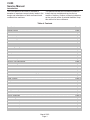
1
CU50
Service Manual
Introduction:
This ice machine is the result of Scotsman’s
decades of experience as an industry leader in the
design and manufacture of both commercial and
residential ice machines.
This manual includes the information needed to
install, start up, maintain and service the ice
machine. Note any Caution or Warning indicators,
as they provide notice of potential hazards. Keep
this manual for future reference.
Table of Contents
Specifications . . . . . . . . . . . . . . . . . . . . . . . . . . . . . . . . . . . . . . . . . . Page 2
Cabinet Layout . . . . . . . . . . . . . . . . . . . . . . . . . . . . . . . . . . . . . . . . . Page 3
Air flow . . . . . . . . . . . . . . . . . . . . . . . . . . . . . . . . . . . . . . . . . . . . . Page 4
Water Quality . . . . . . . . . . . . . . . . . . . . . . . . . . . . . . . . . . . . . . . . . . Page 5
Door Covering . . . . . . . . . . . . . . . . . . . . . . . . . . . . . . . . . . . . . . . . . . Page 6
Door Panel Attachment . . . . . . . . . . . . . . . . . . . . . . . . . . . . . . . . . . . . . Page 7
Custom Panel . . . . . . . . . . . . . . . . . . . . . . . . . . . . . . . . . . . . . . . . . . Page 8
Door swing change . . . . . . . . . . . . . . . . . . . . . . . . . . . . . . . . . . . . . . . Page 9
Installation: Water & Drain
. . . . . . . . . . . . . . . . . . . . . . . . . . . . . . . . . . . Page 10
Gravity Drain . . . . . . . . . . . . . . . . . . . . . . . . . . . . . . . . . . . . . . . . . . Page 11
Electrical
. . . . . . . . . . . . . . . . . . . . . . . . . . . . . . . . . . . . . . . . . . . . Page 12
Cube Size Adjustment
. . . . . . . . . . . . . . . . . . . . . . . . . . . . . . . . . . . . . Page 13
Harvest Time Adjustment . . . . . . . . . . . . . . . . . . . . . . . . . . . . . . . . . . . . Page 14
Control Settings . . . . . . . . . . . . . . . . . . . . . . . . . . . . . . . . . . . . . . . . . Page 15
Use . . . . . . . . . . . . . . . . . . . . . . . . . . . . . . . . . . . . . . . . . . . . . . . Page 16
How to clean the condenser and winterize. . . . . . . . . . . . . . . . . . . . . . . . . . . . Page 17
How to remove scale from the ice making system. . . . . . . . . . . . . . . . . . . . . . . . Page 18
System Information . . . . . . . . . . . . . . . . . . . . . . . . . . . . . . . . . . . . . . . Page 19
Water System . . . . . . . . . . . . . . . . . . . . . . . . . . . . . . . . . . . . . . . . . . Page 20
Components
. . . . . . . . . . . . . . . . . . . . . . . . . . . . . . . . . . . . . . . . . . Page 21
Controller . . . . . . . . . . . . . . . . . . . . . . . . . . . . . . . . . . . . . . . . . . . . Page 22
Performance Information . . . . . . . . . . . . . . . . . . . . . . . . . . . . . . . . . . . . Page 23
Refrigeration System . . . . . . . . . . . . . . . . . . . . . . . . . . . . . . . . . . . . . . Page 24
Thermistor Values . . . . . . . . . . . . . . . . . . . . . . . . . . . . . . . . . . . . . . . . Page 25
Service Diagnosis . . . . . . . . . . . . . . . . . . . . . . . . . . . . . . . . . . . . . . . . Page 26
Service Diagnosis . . . . . . . . . . . . . . . . . . . . . . . . . . . . . . . . . . . . . . . . Page 27
Removal and Repair
. . . . . . . . . . . . . . . . . . . . . . . . . . . . . . . . . . . . . . Page 28
Removal and Repair
. . . . . . . . . . . . . . . . . . . . . . . . . . . . . . . . . . . . . . Page 29
Removal and Repair - Cabinet Removal . . . . . . . . . . . . . . . . . . . . . . . . . . . . Page 30
Refrigeration Service . . . . . . . . . . . . . . . . . . . . . . . . . . . . . . . . . . . . . . Page 32
March 2010
Page 1
CU50
Service Manual
Specifications
This ice machine is designed to be used in a
controlled environment. It can be used in a wide
variety of environmental conditions and under
limited conditions (see user manual), outdoors, but
there are limits. Use outside of the listed limitations
is misuse and will void the warranty.
Air temperature limits:
The ice machine will operate adequately within the
limits, but functions best in temperatures between
70 and 80 degrees F.
• Minimum – 50 degrees F. (10oC)
• Maximum – 100 degrees F. (38oC)
Options:
Kickplate Extension: In some situations the leg
levelers will be extended enough to become visible.
A kit to extend the kickplate over the legs is KKPF.
Cabinet Stability: In some free standing
installations it may be prudent to add a bracket that
secures the back of the cabinet to a wall. That kit
number is KATB.
Drain Conversion:
A gravity drain model can be converted to a drain
pump model by installing a drain pump kit. The
drain pump kit consists of a drain pump, wiring
harness and associated tubing. The kit number is
A39462-021.
Water temperature limits:
• Minimum – 40 degrees F. (4.5oC)
• Maximum – 100 degrees F. (38oC)
Warranty Information
Warranty information is supplied separately from
this manual. Refer to it for coverage. In general, the
warranty covers defects in materials or
workmanship and does not cover corrections of
installation errors or maintenance.
Water pressure limits:
• Minimum – 20 psi (1.4 bar)
• Maximum – 80 psi (5.5 bar)
Because the ice machine is making a food product,
the water supply to the ice machine must be
potable, or fit for human consumption.
Electrical
• 115 volt, 60 Hz. Plug into dedicated 15 amp
circuit.
• Power consumption: 275 - 400 Watts. Varies
during Freeze and Harvest cycles.
Voltage limits:
• Minimum - 104 volts
• Maximum – 126 volts
Models: There are two models, all air cooled:
• CU50PA-1 – Pump model
• CU50GA-1 – Gravity drain model
March 2010
Page 2
CU50
Service Manual
Cabinet Layout
98.55
3.88
FLOORRAIN
D
ACCESS HOLE
443.23
17.45
606.68
23.89
566.17
22.29
40.51
1.60
377.95
14.88
753.24
29.66
873.25
34.38
DRAIN
FLEXIBLE
TUBING
3/8D.PUMP
I.
MODEL
LUDED)
(INC
5/8D.G
I. RAVITY MODEL
OT INC
(NLUDED)
POTABLE
WATER INLET
1/4"
COMPRESSION
TTINGFI
97.79
3.85
AIR OUT
AIR IN
82.99
3.27
81.28
3.20
LEG
ADJUS
TMENT
[25.40]
1.00
March 2010
Page 3
115
V
POWER
CORD
62.04
2.44
97.16
3.83
188.98
7.44
39.75
1.57
CU50
Service Manual
Air flow
The machine takes in room temperature air at the
lower right front and forces warm air out the lower
left front. Restricting the airflow will adversely affect
the ability of the ice machine to make ice.
Control Panel
Ice Making
Area
Warm Air Out
Air Intake
Scotsman Ice Systems are designed and
manufactured with the highest regard for safety
and performance. They meet or exceed the
standards of agencies like U.L.
Scotsman assumes no liability or responsibility of
any kind for products manufactured by Scotsman
that have been altered in any way, including the
use of any parts and/or other components not
specifically approved by Scotsman.
Scotsman reserves the right to make design
changes and/or improvements at any time.
Specifications and designs are subject to change
without notice.
March 2010
Page 4
CU50
Service Manual
Water Quality
All water, including potable water supplied by
municipalities, contains some impurities or
minerals. Water absorbs impurities from the air as
rain and/or as it flows through the ground. Some of
the impurities are solid particles, these are known
as suspended solids, and a fine particle filter will
remove them. Other impurities are chemically
bonded to the water molecules, and cannot be
filtered out, these are called dissolved solids.
Filters and Treatment
In general, it is always a good idea to filter the
water. A water filter, if it is of the proper type, can
remove taste and odors as well as particles. Some
methods of water treatment for dissolved solids
include reverse osmosis, and polyphosphate
feeders.
RO Water
Ice made by this machine will have a lower mineral
content than the water it was made from. This is
due to the method of making ice. Purer water will
freeze first in the ice making molds. The reason for
this is that anything dissolved in water lowers the
water’s freezing temperature. This concentrates
most of the impurities in the ice machine water
reservoir where they may form hard deposits
known as scale. The machine dilutes the
concentration of minerals by over-filling the
reservoir during the harvest cycle (with the excess
water flowing down the drain). Between 2 and 4
pints of water flow into the unit each cycle.
Between 1 and 3.5 pints of that rinses the reservoir
and goes down the drain.
This machine can be supplied with Reverse
Osmosis water, but the water conductivity must be
no less than 10 microSiemens/cm. A reverse
osmosis system should include post treatment to
satisfy the R.O. water’s potential aggressiveness.
Deionized water is not recommended and is too
clean to allow the machine to function.
Because water softeners exchange one mineral for
another, softened water may not improve water
conditions when used with ice machines. Where
water is very hard, softened water could result in
white, mushy cubes that stick together.
If in doubt about the water, contact a local point of
Some impurities will inevitably remain, and will stick use water specialist for recommendations on water
to the parts in the machine, and will cause
treatment.
malformed ice cubes. Eventually, built up mineral
Installation Overview
scale can shorten machine life.
The ice machine must:
To keep the machine operating properly, these
impurities or minerals will have to be regularly
dissolved by an acid cleaning, using Scotsman Ice
• be connected to cold, potable water
Machine Scale Remover. Directions for this may be
• be connected to a drain
found in the section under cleaning.
• be connected to the proper power supply
• be able circulate air through the vents at the
front.
Note: Do not build in so that the door is recessed.
March 2010
Page 5
CU50
Service Manual
Door swing change
The door can be attached to open with hinges on
the left or right. Retain all screws for re-use.
6. Remove original bottom hinge.
To change:
1. Remove top hinge pin from hinge.
7. Remove two plugs or screws from upper
cabinet bracket.
8. Attach bottom hinge to upper cabinet bracket
using the original screws.
9. Place the door on bottom hinge, tip up to slide
under top hinge.
2. Tilt top of door away from cabinet and lift door
off bottom hinge.
10. Insert hinge pin into top hinge and door.
11. Tighten hinge pin.
12. Replace screws or plugs into holes left by
hinges.
13. Check action and swing of door.
3. Remove two screws and top hinge.
4. Remove plugs or screws from lower cabinet
bracket
5. Attach top hinge to lower cabinet bracket using
original screws.
March 2010
Page 6
CU50
Service Manual
Installation Notes
Sealing to floor: In some cases the base of the ice
machine must be sealed to the floor to meet local
code. Food grade silastic sealant such as
Scotsman part number 19-0529-01 is
recommended.
Place the machine in the intended location. Turn
the leg levelers in until the bottom of the unit is as
close to the floor as possible. Be sure the unit is
level and all four levelers are in contact with the
floor.
Place a bead of the sealant between the floor and
the outside edge of the cabinet. The bead must fill
the space between the cabinet bottom edges and
the floor.
Built In Situations: If a finished floor is to be
installed in the area after the ice machine has been
built in, shims the expected thickness of the floor
should be installed under the unit to keep the
machine level with the planned floor level.
Installations on a slab: Use a pump model and
pump the water to the point of drainage. Pump
models will pump 1 story (10 feet) high.
Installations over a crawl space or basement:
Either gravity drain or pump model units may be
used, if there is not enough room behind the
machine for a drain/waste receptacle, the drain will
have to be below the floor.
Note: When installed in a corner, the door swing
may be limited due to handle contact with the wall
or cabinet face.
March 2010
Page 7
CU50
Service Manual
Installation: Water & Drain
The recommended water supply tubing is ¼ inch
OD copper. Stainless steel flex or reinforced PVC
tube may also be used. Install an easily accessible
shut-off valve between the supply and the unit. This
shut-off valve should not be installed behind the
unit.
Drains
There are two types of ice machine models, one
that drains by gravity and one that has an internal
drain pump.
Drain Pump Model drain installation
Note: Do not use self-piercing type valves.
1. Locate the coil of 3/8” ID plastic drain tubing
secured to the back of the unit.
1. Remove the front service panel.
2. Route the plastic drain tube from the back of the
unit to the drain connection point.
IMPORTANT NOTE: Often an air gap is required by
local codes between the ice maker drain tube and
the drain receptacle.
Screw
Securing
Front Service
Panel
2. Route the tubing through the right hole in the
back to the inlet water solenoid valve inlet.
3. Install a compression fitting on the tubing and
connect to the inlet of the solenoid.
Water Inlet
Tube (field
supplied)
Drain Tube,
Route to
building drain
Back View, Drain Pump Model
March 2010
Page 8
CU50
Service Manual
Gravity Drain
Caution: Restrictions in the drain system to the
machine will cause water to back up into the ice
storage bin and melt the ice. Gravity drain tubing
must be vented, have no kinks and slope to the
building drain. Air gaps are typically required by
local code.
1. Place the ice machine in front of the installation
opening. Adjust leveling legs to the approximate
height.
2. Remove the front service access panel and the
upper back panel.
Note: If you are connecting a gravity drain model
and the drain opening has been located in the floor
under the base pan according to the pre install
specifications, follow steps 3 through 5 to drain the
unit through the base. If not, proceed to step 6b.
3. Remove the clamp and barbed elbow and take
off the plastic cover in the base pan below the drain
hose.
4. Connect a straight 5/8” barbed connector to the
drain hose, securing with the clamp removed in
step 4.
5. Cut an 8” piece of 5/8” ID X 7/8” OD tygon (clear
plastic) tubing. Slide one end of the tube onto the
outlet of the barbed connector and secure with a
clamp. Leave the other end of the tube lying on the
floor of the base pan until the unit is positioned
over the floor drain.
6. Route the drain tube. Either a) Insert the drain
tube through the base pan into the floor drain or b)
Route the drain tube through the left hole in the
lower back panel and connect to barbed elbow and
secure with a clamp.
7. Reinstall the upper back panel.
8. Reinstall the service access panel. Level the
unit.
Barbed Elbow
Drain Hose
Water Inlet
Tube (field
supplied)
Drain Hose,
Route to
building drain
Back View, Gravity Drain Model
March 2010
Page 9
CU50
Service Manual
Electrical
The ice machine is supplied with a power cord. Do
not remove the grounding pin from the cord’s plug.
Do not use extension cords. Follow all codes.
Connect the machine to its own 115 volt, 15 amp
circuit.
1. If the electrical outlet for the ice maker is
behind the unit, plug in the unit.
1. Has the unit been connected to the proper
water supply?
2. Has the water supply be checked for leaks?
3. Has the unit been connected to a drain?
2. Position the unit in the installation opening.
3. Turn on the water supply. Make sure that the
ice maker is plugged in and the power is on.
4. Slide unit into installation opening, paying
careful attention to water supply and drain
connections. Do not kink!
Installation check list:
4. Has the drain been tested for flow and leaks?
5. Has the unit been connected to the proper
electrical supply?
6. Has the unit been leveled?
7. Have all packing materials been removed from
the machine?
5. Pour a couple of quarts of water into the ice
8. Has the door covering been installed?
storage bin; on drain pump equipped machines
the drain pump should start and water should
Initial Start Up
pump out. Check for leaks.
1. Turn on the water supply.
6. Replace the service access panel.
2. Switch on the electrical power.
7. Level the unit as needed.
3. Push and release the On/Off switch to start the
machine. The Ice Making light next to the
On/Off switch will glow Green.
4. Water will begin to flow into the unit. When the
reservoir is full, water will start to drain from the
machine. After a few minutes the compressor,
water pump and fan motor will begin to operate
and the first ice making cycle will have begun.
No adjustments are needed.
After about a half hour, ice will fall into the ice
storage bin. The machine makes 24 cubes per
batch. It is normal for the first batches of ice to
melt, that continues until the bin has cooled. It will
take 8 to 10 hours of continuous run time to fill the
ice bin. When the bin is full of ice, the ice machine
will shut off. It will automatically restart when the
ice level falls, either from use or normal meltage.
March 2010
Page 10
CU50
Service Manual
Cube Size Adjustment
The cube size can be adjusted by changing the
amount of freeze cycle time. This is done by a
button press sequence.
Side Views of Cubes
Note: There is only one correct cube size. See the
illustrations.
To adjust cube size:
1. Shut the machine off: If it's off on bin full press
and release the On/Off button once, switching the
Ice Making light off. If the machine is making ice
hold the On/Off button in until the Ice Making light
is off.
Too Small, Adjust Cycle Longer
2. Press and hold the Clean button for 5 seconds
(light on), then release (light out)
3. View the lights. Compare to the table below.
Cube Size Change Table
On/Off
Water
Clean
Default
off
off
off
Add 1 minute
on
off
off
Add 2 minutes
off
on
off
Add 3 minutes
off
off
on
Add 4 minutes
on
on
on
- 1 minute
flash
off
off
- 2 minutes
off
flash
off
- 3 minutes
off
off
flash
- 4 minutes
flash
flash
flash
Just Right
Too Large, Adjust Cycle Shorter
4. Select the amount of change.
5. Push and release the On/Off button until the
correct light pattern is displayed.
6. Push and release the Clean button to select that
setting.
7. Push and release On/Off to return to ice making.
March 2010
Page 11
CU50
Service Manual
Harvest Time Adjustment
The harvest time can be adjusted so that all the ice
harvests during the cycle, plus a few seconds
extra. This is done by a button press sequence.
Harvest Time Table
On/Off
Water
Clean
Default
off
off
off
Add 10 seconds
on
off
off
Add 20 seconds
off
on
off
Add 30 seconds
off
off
on
1. Shut the machine off by holding the On/Off
button in until it shuts off (Ice Making light off).
Add 40 seconds
on
on
on
- 10 seconds
flash
off
off
2. Press and hold the On button again for 5
seconds, then release (Ice Making light will switch
off).
- 20 seconds
off
flash
off
- 30 seconds
off
off
flash
- 40 seconds
flash
flash
flash
Note: Do not set harvest time shorter than the
actual time it takes to release all the cubes.
To adjust Harvest Time:
3. View the lights. Compare to the table below.
4. Select the amount of change.
5. Push and release the Clean button until the
correct light pattern is displayed.
6. Push and release the On button to select that
setting.
7. Push and release On/Off to return to ice making.
Ice Making
Indicator Light
On - Off
Button
Check Water
Indicator Light
Time To
Clean Unit
Indicator Light
Control Panel
March 2010
Page 12
Clean - Reset
Button
CU50
Service Manual
Control Settings
Automatic water purge enable / disable
The control is set at the factory to automatically
select the proper amount of water purge. If desired,
that can be disabled, and a typical purge amount
used.
To disable Automatic purge selection:
1. Press and hold the On/Off button until the unit
shuts off. No lights should be on.
2. Press and hold the ON button for 5 seconds,
then release.
3. Wait between 5 and 20 seconds, then repeat
step 1. All lights will flash once.
To return to Automatic purge selection:
1. Press and hold the ON button for 5 seconds,
then release.
2. Wait between 5 and 20 seconds, then repeat
step 1. All lights will flash twice.
Manual Harvest - from the OFF or Standby Mode
(powered but no lights are on)
1. Press and hold the Clean-Reset button for 5
seconds and release.
2. Wait between 5 and 20 seconds, then repeat
step 1. All lights will flash once. The On/Off light will
be on until harvest has timed out.
Reset time to clean indicator light
Press and hold the Clean-Reset button for 3
seconds.
March 2010
Page 13
CU50
Service Manual
Use
No special instructions are needed for use. Just
take as much ice as you need, the machine will
replace it. A scoop is provided, and it can be stored
in the machine using the loop of tubing on the right
side as a holder.
The machine can be shut off anytime by just
pushing and releasing the On/Off button. The
machine will shut off at the end of the next cycle.
To shut off immediately, push and hold the On/Off
button in until the machine stops.
What shouldn’t be done?
Never keep anything in the ice storage bin that is
not ice. Objects like wine or beer bottles are not
only unsanitary, but the labels can slip off and plug
up the drain.
Never allow the machine to operate without regular
cleaning. The machine will last longer if it is kept
clean. Regular cleaning should happen at least
once per year, and preferably twice. Some water
conditions will dictate even more frequent cleaning
of the ice making section, and some carpets or
pets will dictate more frequent cleaning of the
condenser.
Normal cubes are tapered cylinders. If the cubes
are ragged and mis-shaped, mineral scale must be
removed from the ice making system
Maintenance
There are 5 things to keep clean:
1. The outside cabinet & door.
2. The ice storage bin.
3. The condenser.
4. The ice making system.
5. The ice scoop.
Note: The Time to Clean light will switch ON after 6
months of use. It will remain ON until the ice
How to clean the cabinet.
making system is cleaned using the process on
page 13.
Wipe off any spills on the surface of the door and
handle as they occur. If anything spilled on the
door or gasket dries onto the surface, wash with
Noise:
soap and warm water to remove.
The ice machine is designed for quiet operation,
How to clean the ice storage bin.
but will make some noise during the ice making
cycle. During a freezing cycle, it is normal to hear
The ice storage bin should be sanitized
the fan moving air and the water pump circulating
occasionally. It is usually convenient to sanitize the
water. Ice hitting the bin or ice in the bin can be
bin after the ice making system has been cleaned,
heard during harvest.
and the storage bin is empty.
A sanitizing solution can be made of 1 ounce of
household bleach and two gallons of hot (95 oF. –
115oF.) water. Use a clean cloth and wipe the
interior of the ice storage bin with the sanitizing
solution, pour some of the solution down the drain.
Allow to air dry.
March 2010
Page 14
CU50
Service Manual
How to clean the condenser and winterize.
Condenser cleaning
Winterizing
The condenser is like the radiator on a car, it has
fins and tubes that can become clogged with dirt
and lint. To clean:
1. Clean the ice making system.
2. Open the door and push and release the On/Off
switch to turn the machine off.
1. Remove the kickplate and front service panel.
3. Turn off the water supply.
2. Locate the condenser surface.
4. Drain the water reservoir by removing the rubber
cap under the reservoir - it's near the back wall of
the ice storage bin.
Rubber Cap
5. Disconnect the incoming water line at the inlet
water valve.
3. Vacuum the surface, removing all dust and lint.
Caution: Do not dent the fins.
4. Return the kickplate and front service panel to
their original positions. Fasten them to the cabinet
using the original screws.
6. Open the door, push and release the on/off
switch to turn the machine on.
7. Blow air through the inlet water valve; a tire
pump could do the job.
8. Drain pump models should have about 1/2
gallon of RV antifreeze (propylene glycol) poured
into the ice storage bin drain.
Note: Automotive antifreeze must NOT be used.
9. Switch off and unplug the machine.
March 2010
Page 15
CU50
Service Manual
How to remove scale from the ice making system.
1. Scoop out all of the ice, either discard it or save
it in an ice chest or cooler.
9. Pour a gallon of hot (95oF. – 115oF.) water into
the bin to flush out the drain.
2. Press and HOLD the On/off button in for 3
seconds until the Green light goes out.
10. Clean the bin liner of mineral scale by mixing
some ice machine scale remover and hot water,
and using that solution to scrub the scale off of the
liner.
11. Rinse the liner with hot water.
12. Sanitize the bin interior.
3. Press and HOLD the both the Clean-Reset and
On/Off buttons for 5 seconds. The Time to Clean
light will blink on and off.
4. Pour 8 ounces of Scotsman Ice Machine Scale
Remover (available from a local Scotsman
Distributor or Dealer) into the ice machine
reservoir.
13. Replace the ice removed in step 1.
14. Push and release the On/Off button to restart
ice making.
The ice scoop should be washed regularly, wash it
just like any other food container.
Pour Scale
Remover Here
5. Operate the machine for about ½ hour.
6. Push and release the On/Off switch. The
machine will begin to flush out the cleaning
solution.
7. Operate the machine for another ½ hour.
8. Push and release the On/Off switch. The
machine will stop the cleaning process.
March 2010
Page 16
CU50
Service Manual
System Information
Overall:
•
•
•
•
•
•
•
•
•
•
•
•
•
•
•
•
•
•
•
•
•
Refrigerant: 8 oz R-134a
Compressor: Hermetic, 1300 BTUH,
Condenser: Forced draft
Fan blade: 5 blade, 7 inch
Evaporator: Inverted, 24 cube cells. Copper
cups attached to continuous serpentine
Metering device: Cap tube
Defrost method: Hot gas bypass with water
assist
Spray method: 6 water jets
Water charge: 40 ounces
Water valve: 115 volt solenoid, .19 GPM
Water fill time: Varies with harvest time &
purge setting
Spray pump: Pedestal type.
Drain pump: Magnetic drive, controlled by
pressure switch
Purge method: Overflow standpipe
Control method: Electronic
Cycle control: Thermistor + timers
Freeze cycle timer: 10 minutes, + - 4
Harvest cycle timer: 20 seconds, + - 40
Cube size adjustment: Freeze timer change.
Harvest cycle adjustment: Harvest timer
change
Bin control: Thermostat. Opens on
temperature fall, Cut Out: 35 degrees F. Cut
In 45 degrees F. Range is adjustable.
Electrical Components:
•
•
•
•
•
•
•
•
•
•
•
•
Electrical Sequence:
Compressor
Fan motor
Spray pump motor
Drain pump motor
Drain pump switch
Inlet water solenoid valve
Hot gas valve
Transformer
Controller
Water sensor
Thermistor
Bin thermostat
A closed bin thermostat signals to the controller a
need for ice. The controller checks for water, if
water is needed , the controller opens the inlet
water solenoid valve to fill the reservoir. The hot
gas valve is open to equalize the system. When the
reservoir is full, the compressor, fan motor, water
pump are switched on. After 5 seconds the hot gas
valve shuts and ice making begins.
Water is sprayed up into the inverted cup mold. As
the water is cooled and ice begins to form in the
cups, the temperature of the evaporator will fall.
The freeze cycle continues until the temperature of
the thermistor attached to the evaporator outlet
tube falls to about zero degrees F. At that point the
controller starts a freeze cycle timer, whose default
time is 10 minutes. At the end of the freeze cycle's
timed portion the controller switches to the harvest
cycle.
The harvest cycle begins with the controller
stopping the water pump and fan motor. At the
same time it opens the hot gas valve and the inlet
water solenoid valve. The ice is released by the
combination of discharge refrigerant gas entering
the evaporator serpentine and warming up the
copper, plus the inlet water that flows to the
evaporator, floods across the plastic platen to
warm it up and be pre-chilled for the next cycle. Ice
cubes drop individually and harvest continues until
the thermistor attached to the suction line warms
up to about 50 degrees F. At that point a harvest
timer starts, whose default time is 20 seconds. At
the end of that time the harvest cycle ends and the
freeze cycle restarts.
Bin control.
The machine's on and off modes are regulated by a
bin thermostat. The cap tube for the bin thermostat
is in the tube that holds the scoop. The machine
will only begin ice making when the thermostat's
contacts close. If the contacts re-open before the
temperature of the evaporator drops below a preset
point, the machine will stop. If the temperature is
below that point when the contact s open, the
machine will continue through a complete cycle
and stop at the end of the harvest cycle.
March 2010
Page 17
CU50
Service Manual
Water System
The controller uses a Water Sensor to check for
the presence of water in the reservoir and to
measure the conductivity of the water.
Evaporator
The water sensor consists of two stainless steel
probes located in a holder next to the water pump.
The probes sense the conductivity of the water.
The higher the mineral content of the water, the
better it can conduct electricity. The control system
is capable of sensing water as clean as 10
microSiemens/cm.
Pump
If the controller cannot sense water and the bin
thermostat is closed the controller will power the
inlet water solenoid valve to fill the reservoir. The
water fill is timed. There is a maximum amount of
time allowed from the time the controller turned on
the inlet water valve until the water sensor signals
to the controller. That time is 2 1/2 minutes. If
water is not sensed within 2 1/2 minutes, the
controller will not proceed with an ice making
cycle. Instead it will blink the Water light and try
filling the reservoir in 20 minutes.
Reservoir
Drain
Freeze Cycle Water Schematic
Reservoir water dilution
The process of making ice from circulating water
causes the pure water to freeze first, because it
freezes at the warmest temperature. The remaining
water will develop an increasing concentration of
minerals. If that mineral concentration were
allowed to continue, eventually the ice machine
would become coated with mineral scale.
To combat the mineral build up, the reservoir water
is diluted with fresh water every cycle. The
controller adds enough water to fill the reservoir
and extra water to overfill it. The extra water drains
out through the standpipe in the reservoir.
The controller keeps the inlet water solenoid valve
open until the evaporator temperature set point is
reached, plus some extra time. The extra time is
either pre-set or automatically determined by the
controller.
March 2010
Page 18
Standpipe
Inlet Water Solenoid Valve
Harvest Cycle Water Schematic
CU50
Service Manual
Components
Model and
Serial Tag
Location
Scoop and Thermostat Bracket
Control Panel, Bin Light and Curtain
Evaporator Platen
Evaporator and Controller
Inlet Water Solenoid Valve
Condenser and Bin Thermostat
March 2010
Page 19
CU50
Service Manual
Controller
High
Voltage
Connector
Evaporator
Thermistor
Bin
Thermostat
Comp
Water Sensor
Water
Hot Gas
Fan
Power
Power Supply
Connector
Control Panel
Ribbon
The controller is located at the front of the unit,
under the top panel.
It is powered by a 12 volt transformer. It has 5
indicator lights:
• Compressor - Light is ON if compressor is
•
•
•
•
powered
Water - Light is ON if inlet water solenoid
valve is powered
Hot Gas - Light is ON when Hot Gas Valve is
powered
Fan - Light is ON when Fan motor is
powered
Power - Light is ON when power is
connected to controller
Control Safeties:
No Water. If the Water Sensor cannot detect
water, and the inlet water solenoid valve has been
on for the maximum fill time, the controller will stop
all action and wait 20 minutes to re-try water fill.
During this time the Check Water light on the
control panel will be blinking,
Maximum Freeze Time. If the freeze cycle should
extend to 60 minutes, the controller will
automatically put the machine into a Harvest cycle.
Maximum Harvest Time. 6 minutes
Time between restarts. After the machine has
operated and then turned off, the controller will not
restart the machine for four minutes.
March 2010
Page 20
CU50
Service Manual
Performance Information
Freeze Cycle, Minutes
Water
Temperature
100
90
80
70
60
50
100
37-38
36-37
34-35
32-33
31-32
29-30
90
36-37
35-36
33-34
31-32
30-31
28-29
80
36-35
32-33
30-31
28-29
27-28
26-27
70
32-33
28-29
27-28
25-26
23-24
22-23
60
27-28
25-26
24-25
22-23
20-21
19-20
50
20-21
19-20
18-19
17-18
16-17
15-16
40
18-19
17-18
16-17
15-16
15-16
15-16
Harvest Cycle, Seconds
Water
Temperature
Air Temperature
100
90
80
70
60
50
80 -100
55-60
60-70
70-80
80-90
90-100
110-115
70 - 80
65-75
70-80
75-85
85-95
95-105
115-120
50 - 70
70-80
75-85
85-95
125-135
140-150
160-170
40 - 50
100-120
115-125
130-140
150-170
180-200
210-230
Total Cycle, Minutes
Water
Temperature
Air Temperature
Air Temperature
100
90
80
70
60
50
100
38-39
37-38
36-37
34-35
33-34
31-32
90
38-39
36-37
35-36
33-34
32-33
30-31
80
37-38
33-34
31-32
30-31
29-30
27-28
70
33-34
29-31
28-29
26-27
25-26
24-25
60
29-30
27-28
25-26
24-25
22-23
21-22
50
21-22
20-21
19-20
19-20
19
18-19
40
20-21
19-20
19
18-19
19
19-21
Ice per cycle: 1 lb
Water drained / cycle: Varies by harvest cycle
length and purge setting. Typical amounts are @
70/50 = 52 oz. @ 90/70 = 13 oz
Compressor amps: 2.6 - 3.2
March 2010
Page 21
CU50
Service Manual
Refrigeration System
Suction Pressure
70
60
50
PSIG
40
30
20
10
0
-10
Time
Discharge Pressure
150
140
130
120
PSIG
110
100
90
80
70
60
50
Time
March 2010
Page 22
CU50
Service Manual
Thermistor Values
Deg. F · Ohms
0·
1·
2·
3·
4·
5·
6·
7·
8·
9·
10
11
12
13
14
15
16
17
18
19
20
21
22
23
24
25
26
27
28
29
30
31
32
33
34
35
36
37
38
39
40
41
42
43
44
45
46
47
48
49
50
51
·
·
·
·
·
·
·
·
·
·
·
·
·
·
·
·
·
·
·
·
·
·
·
·
·
·
·
·
·
·
·
·
·
·
·
·
·
·
·
·
·
·
·
·
·
·
·
·
·
·
·
·
·
·
·
·
·
·
·
·
·
·
·
·
·
·
·
·
·
·
·
·
·
·
·
·
·
·
·
·
·
·
·
·
·
·
·
·
·
·
·
·
·
·
·
·
·
·
·
·
·
·
·
·
·
·
·
·
·
·
·
·
·
·
·
·
·
·
·
·
·
·
·
·
·
·
·
·
·
·
·
·
·
·
·
·
·
·
·
·
·
·
·
·
·
·
·
·
·
·
·
·
·
·
·
·
85325
82661
80090
77607
75210
72896
70660
68501
66415
64400
62453
60571
58752
56995
55296
53653
52065
50529
49043
47607
46217
44872
43571
42313
41094
39915
38774
37669
36600
35564
34561
33590
32649
31738
30855
30000
29171
28368
27589
26835
26104
25395
24707
24041
23394
22767
22159
21569
20997
20442
19903
19381
Deg. F · Ohms
52 ·
S3 ·
54 ·
55 ·
56 ·
57 ·
58 ·
59 ·
60 ·
61 ·
62 ·
63 ·
64 ·
65 ·
66 ·
67 ·
68 ·
69 ·
70 ·
71 ·
72 ·
73 ·
74 ·
75 ·
76 ·
77 ·
78 ·
79 ·
80 ·
81 ·
82 ·
83 ·
84 ·
85 ·
86 ·
87 ·
88 ·
89 ·
90 ·
91 ·
92 ·
93 ·
94 ·
95 ·
96 ·
97 ·
98 ·
99 ·
100
101
102
103
·
·
·
·
·
·
·
·
·
·
·
·
·
·
·
·
·
·
·
·
·
·
·
·
·
·
·
·
·
·
·
·
·
·
·
·
·
·
·
·
·
·
·
·
·
·
·
·
·
·
·
·
·
·
·
·
·
·
·
·
·
·
·
·
·
·
·
·
·
·
·
·
·
·
·
·
·
·
·
·
·
·
·
·
·
·
·
·
·
·
·
·
·
·
·
·
·
·
·
·
·
·
·
·
18873
18381
17903
17439
16988
16551
16126
15714
15313
14924
14546
14179
13823
13476
13139
12812
12494
12185
11884
11592
11308
11031
10763
10502
10247
10000
9760
9526
9299
9077
8862
8652
8448
8250
8056
7868
7685
7507
7333
7164
6999
6839
6683
6530
6382
6238
6097
5960
5826
5696
5569
5446
Deg. F. · Ohms
104
105
106
107
108
109
110
111
112
113
114
115
116
117
118
119
120
121
122
123
124
125
126
127
128
129
130
131
132
133
134
135
136
137
138
139
140
141
142
143
144
145
146
147
148
149
150
151
152
153
154
155
·
·
·
·
·
·
·
·
·
·
·
·
·
·
·
·
·
·
·
·
·
·
·
·
·
·
·
·
·
·
·
·
·
·
·
·
·
·
·
·
·
·
·
·
·
·
·
·
·
·
·
·
·
·
·
·
·
·
·
·
·
·
·
·
·
·
·
·
·
·
·
·
·
·
·
·
·
·
·
·
·
·
·
·
·
·
·
·
·
·
·
·
·
·
·
·
·
·
·
·
·
·
·
·
5325
5208
5093
4981
4872
4766
4663
4562
4463
4367
4273
4182
4093
4006
3921
3838
3757
3678
3601
3526
3452
3381
3311
3243
3176
3111
3047
2985
2924
2865
2807
2751
2696
2642
2589
2537
2487
2438
2390
2343
2297
2252
2208
2165
2123
2082
2042
2003
1965
1927
1890
1855
March 2010
Page 23
Deg. F.
156
157
158
159
160
161
162
163
164
165
166
167
168
169
170
171
172
173
174
175
176
177
178
179
180
181
182
183
184
185
186
187
188
189
190
191
192
193
194
195
196
197
198
199
200
201
202
203
204
205
206
207
·
·
·
·
·
·
·
·
·
·
·
·
·
·
·
·
·
·
·
·
·
·
·
·
·
·
·
·
·
·
·
·
·
·
·
·
·
·
·
·
·
·
·
·
·
·
·
·
·
·
·
·
Ohms
·
·
·
·
·
·
·
·
·
·
·
·
·
·
·
·
·
·
·
·
·
·
·
·
·
·
·
·
·
·
·
·
·
·
·
·
·
·
·
·
·
·
·
·
·
·
·
·
·
·
·
·
1819
1785
1752
1719
1687
1655
1624
1594
1565
1536
1508
1480
1453.
1427
1401
1375
1350
1326
1302
1279
1256
1234
1212
1190
1169
1149
1129
1109
1090
1071
1052
1034
1016
998
981
965
948
932
916
901
885
871
856
842
828
814
800
787
774
761
749
737
Deg. F. · Ohms
208
209
210
211
212
213
214
215
216
217
218
219
220
221
222
223
224
225
226
227
228
229
230
231
232
233
234
235
236
237
238
239
240
241
242
243
244
245
246
247
246
249
250
·
·
·
·
·
·
·
·
·
·
·
·
·
·
·
·
·
·
·
·
·
·
·
·
·
·
·
·
·
·
·
·
·
·
·
·
·
·
·
·
·
·
·
·
·
·
·
·
·
·
·
·
·
·
·
·
·
·
·
·
·
·
·
·
·
·
·
·
·
·
·
·
·
·
·
·
·
·
·
·
·
·
·
·
·
·
724
713
701
690
679
668
657
646
636
626
616
606
597
587
578
569
560
551
543
534
526
518
510
502
495
487
480
472
465
458
451
444
438
431
425
419
412
406
400
394
389
383
377
CU50
Service Manual
Service Diagnosis
No Ice
Problem
Likely Cause
Probable Solution
No power to unit
Power disconnected
Check breaker or fuse. Reset or
replace, restart and check
No power to controller
Transformer open
Replace transformer
Shut down on maximum
water fill time - water light
flashing
Water shut off
Restore water supply
Water leak
Check curtain, sump
Dirty condenser
Clean condenser
Restricted location, intake air too
hot or blocked
Eliminate restriction, have machine
moved
Evaporator thermistor not sensing
properly
Check thermistor
Spray jets dirty
Remove spray platform and clean
spray jets
Inlet water valve leaks through
during freeze
Check inlet water valve
Low on refrigerant
Check cube formation,
Connected to hot water
Check for bleed thru from / missing
check valve in building water
supply
Spray pump not pumping
Check pump motor
Fan motor not turning
Check fan motor, check fan blade,
check controller for voltage output
Pump hose disconnected
Check hose
Very low on refrigerant
Add access valve, add refrigerant
as a test. If unit makes ice, find and
correct leak.
Very long freeze cycle
Cannot make ice
Compressor not operating
Check compressor start
components, check PTCR
resistance and temperature
Check compressor voltage
Check compressor windings
Hot gas valve leaks through during
freeze
Check hot gas valve for hot outlet
during freeze
Compressor inefficient
Check compressor amp draw, if
low and all else is correct, change
compressor
March 2010
Page 24
CU50
Service Manual
Service Diagnosis
Makes excessive noise
Problem
Likely Cause
Probable Solution
Blade is bent
Replace fan blade
Fan motor mount is broken
Replace motor mount
Compressor vibrates
Mounting loose
Check mounting
Water pump vibrates
Pump bearings worn
Replace pump
Panels vibrate
Mounting screws loose
Tighten screws
Problem
Likely Cause
Probable Solution
Ice wrong size
Environment changed
Adjust cube size
Hot gas valve does not open
Check voltage to coil when unit is
in harvest, check controller
indicator light.
Water temperature very low
Adjust harvest time
Fan motor does not stop
Check voltage, replace controller
Problem
Likely Cause
Probable Solution
Spray pattern poor
Spray jets dirty
Clean jets
Runs out of water
Water leaking from reservoir
Correct leak
High TDS water supply
Groundwater supply
Treat water
Problem
Likely Cause
Probable Solution
Restricted drain
Gravity drain hose has air block
Check for kinks or traps
Pooled water in bin
Pump model switch not starting
pump
Check / replace switch
Fan blade vibrates
Makes ice, does not harvest
Little heat to evaporator
Makes poor quality ice
Makes ice, but melts rapidly
March 2010
Page 25
CU50
Service Manual
Removal and Repair
Bin Thermostat
9. Reverse to reassemble.
1. Disconnect electrical power.
Curtain
1. Shut unit off.
2. Loosen both thumbscrews holding curtain
bracket to freezing chamber.
Electrical Shock
Hazard.
Disconnect electrical
power before
beginning removal
3. Pull out and remove curtain with bracket from ice
machine.
2. Remove service panel.
4. Reverse to reassemble.
3. Remove back panel.
Spray Platform
Note: If unit is built in it must be pulled out to
change the bin thermostat.
1. Remove curtain.
2. Lift spray platform up until it disconnects from its
fitting.
4. Pull cap tube out from the back of the ice
storage bin and cap tube holder.
3. Pull forward and remove from the ice machine.
5. Remove two screws and the bin thermostat
contact section from its mounting bracket.
4. Reverse to reassemble.
6. Disconnect two wires from the bin thermostat
contact section and remove the thermostat from
the ice machine.
Water Pump
1. Remove spray platform
2. Remove back panel.
7. Reverse to reinstall.
Note: If unit is built in it must be pulled out to
change the water pump.
Inlet Water Solenoid Valve
1. Disconnect electrical power.
2. Remove service panel.
3. Disconnect power and ground wires from pump
motor.
3. Shut water supply OFF.
4. Rotate pump body CW and lift up to remove it.
4. Disconnect inlet water supply tube from inlet
water solenoid valve.
5. Reverse to reassemble.
5. Unplug wire harness from valve coil.
6. Remove two screws holding valve to chassis.
7. Squeeze hose clamp larger and push away from
solenoid valve outlet.
8. Pull hose from outlet of valve.
March 2010
Page 26
CU50
Service Manual
Removal and Repair
5. Remove screws holding transformer to controller
box and pull transformer up and out of the ice
machine.
Evaporator Thermistor
Note: If unit is built in it must be pulled out to
change the evaporator thermistor.
6. Reverse to reassemble.
Controller
Note: If unit is built in it must be pulled out to
change the controller.
Electrical Shock
Hazard.
Disconnect electrical
power before
beginning removal
1. Disconnect electrical power.
2. Remove top panel
1. Shut machine off. If unit was making ice,
manually harvest the ice.
3. Remove controller box cover.
2. Disconnect electrical power.
4. Unplug all connections.
3. Remove top panel.
5. Remove screws holding controller to housing,
and lift controller from unit.
4. Remove cover from controller box.
5. Disconnect thermistor wire from controller.
6. Locate thermistor sensor, it is attached to the
suction line, just above the accumulator and is
covered with insulation tape. Remove the
insulation.
Note: To avoid damaging the controller, touch the
metal chassis of the unit prior to touching the
replacement controller.
6. Reverse to reassemble.
Control Panel
7. Disconnect sensor bulb from suction line (it's
held on with a metal clip).
1. Disconnect electrical power.
8. Remove thermistor from ice machine.
2. Remove top panel
9. Reverse to reassemble. It is very important that
the bulb be re-insulated.
3. Remove controller box cover.
Transformer
Note: If unit is built in it must be pulled out to
change the transformer.
1. Disconnect electrical power.
2. Remove top panel.
4. Unplug ribbon cable connection.
5. Push control panel away from the front of the
machine. Begin at the ribbon cable attachment
point.
Note: Control panel is held on by adhesive and the
adhesive is thinnest at the cable point.
3. Remove controller cover.
6. Separate control panel from controller box and
remove from the ice machine.
4. Unplug leads from transformer.
7. Reverse to reassemble.
March 2010
Page 27
CU50
Service Manual
Removal and Repair - Cabinet Removal
Certain components require the removal of the
cabinet for repair access.
12. Remove curtain & hanger.
1. If the machine is in a freeze mode, perform a
manual harvest.
2. Remove all ice.
3. Drain reservoir.
4. Remove service panel and kick plate.
5. Remove back panel.
13. Locate elbows where water flows onto the
evaporator platen.
6. Disconnect electrical power.
Clip
Electrical Shock
Hazard.
Disconnect electrical
power before
beginning removal
Inlet
Elbow
7. Disconnect water and drain tubing.
8. Remove door.
14. Pull clip up. Push inner elbow back and rotate it
until it points straight up, then push it back through
the hole in the back of the freezing compartment.
9. Remove top panel.
10. Remove controller box cover.
11. Disconnect thermistor from controller, pull wire
back to suction line.
Thermistor
Connector
Inlet
Elbow
Inner
Elbow
15. Pull water inlet elbow out of inner elbow.
March 2010
Page 28
CU50
Service Manual
23. Lift bin assembly off the base.
18. Remove two screws holding freezing
compartment brace to cabinet, lift brace up.
Note: Prop evaporator assembly up. A 3' length of
3/4" PVC tubing with one end inserted into the cup
mold and the other against the base will hold it up.
Brace
The hot gas valve, fan motor, condenser and
compressor are now exposed for service.
19. Lift evaporator platen up and tilt back enough
for bin assembly to clear the base.
Air Baffle
20. Remove air baffle.
21. Unplug 7 wire harness connector (at back of
bin).
22. Remove 1 screw at each corner of the base.
March 2010
Page 29
Chassis Shown in Front of Bin Assembly
CU50
Service Manual
Refrigeration Service
This ice machine use R-134a type refrigerant.
There are specific rules for handling that
refrigerant.
To check for system pressures, add a field supplied
clamp-on type service valve as a temporary means
of system access. After diagnosis and before final
repair, replace the clamp-on type valve with valves
that are brazed onto the process tubes of the
system.
Use a low flow of dry nitrogen when brazing on the
system.
Install a new filter drier when replacing a
refrigeration component or after a refrigerant leak
repair.
Evacuate the system to at least 300 microns and
use a micron gauge to measure the evacuation
level.
Weigh in the nameplate charge. The machine is
critically charged and a partial ounce mis-charge
will affect performance.
March 2010
Page 30