1
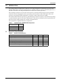
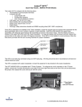
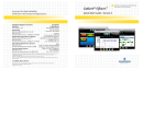
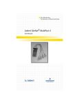
AC Power
For Business-Critical Continuity™
Liebert® LBS Controller™ for Liebert NX™ 225-600kVA
User Manual
TABLE OF CONTENTS
IMPORTANT SAFETY INSTRUCTIONS . . . . . . . . . . . . . . . . . . . . . . . . . . . . . . . . . . . . . . . . . . . . . . . .1
SAVE THESE INSTRUCTIONS . . . . . . . . . . . . . . . . . . . . . . . . . . . . . . . . . . . . . . . . . . . . . . . . .1
1.0
INTRODUCTION . . . . . . . . . . . . . . . . . . . . . . . . . . . . . . . . . . . . . . . . . . . . . . . . . . . . . . . . . .2
1.1
Electrical Characteristics. . . . . . . . . . . . . . . . . . . . . . . . . . . . . . . . . . . . . . . . . . . . . . . . . . . . . . 2
1.2
Mechanical Characteristics . . . . . . . . . . . . . . . . . . . . . . . . . . . . . . . . . . . . . . . . . . . . . . . . . . . . 3
2.0
TYPICAL CONFIGURATION—TWO UPS UNITS WITH COMMON BYPASS LINE . . . . . . . . . . . . .4
FIGURES
Figure 1
Figure 2
Figure 3
Liebert LBS Controller signal cable connections panel reference supply input . . . . . . . . . . . . . . . 3
Front panel UPS synchronization outputs . . . . . . . . . . . . . . . . . . . . . . . . . . . . . . . . . . . . . . . . . . . . 3
Common bypass line . . . . . . . . . . . . . . . . . . . . . . . . . . . . . . . . . . . . . . . . . . . . . . . . . . . . . . . . . . . . . . 4
TABLES
Table 1
Table 2
Table 3
Installation Kit - NX2MODLBS components . . . . . . . . . . . . . . . . . . . . . . . . . . . . . . . . . . . . . . . . . . 2
Electrical characteristics . . . . . . . . . . . . . . . . . . . . . . . . . . . . . . . . . . . . . . . . . . . . . . . . . . . . . . . . . . 2
Liebert LBS Controller port connections . . . . . . . . . . . . . . . . . . . . . . . . . . . . . . . . . . . . . . . . . . . . . . 3
i
ii
Important Safety Instructions
IMPORTANT SAFETY INSTRUCTIONS
SAVE THESE INSTRUCTIONS
This manual presents an overview of the components and use of your Liebert LBS (Load Bus Sync)
Controller. The Liebert LBS Controller must be installed by properly trained and qualified personnel.
Read this manual thoroughly, paying special attention to the sections that apply to your installation,
before working with the UPS. Retain this manual for use by installing personnel.
! WARNING
Risk of electric shock. Can cause injury and death.
Under typical operation and with all UPS doors closed, only normal safety precautions are
necessary. The area around the UPS system should be kept free of puddles of water, excess
moisture and debris.
Special safety precautions are required for maintenance of the UPS system, including the
Liebert LBS Controller and the batteries. Observe all safety precautions in this manual
before working with the UPS system. Observe all precautions in this manual, before as well
as during performance of all maintenance procedures. Observe all battery safety precautions
before working on or near the battery.
This equipment contains circuits that are energized with high voltage. Only test
equipment designed for troubleshooting should be used. This is particularly true for
oscilloscopes. Always check with an AC and DC voltmeter to ensure safety before making
contact or using tools. Even when the power is turned Off, dangerously high electric charges
may exist within the UPS or Liebert LBS Controller.
All power and control wiring should be installed by a qualified electrician. All power
and control wiring must comply with the NEC and applicable local codes.
ONLY qualified service personnel should perform maintenance on the UPS system.
When performing maintenance with any part of the equipment under power, service
personnel and test equipment should be standing on rubber mats. The service personnel
should wear insulating shoes for isolation from direct contact with the floor (earth ground).
Never work alone, even if all power is removed from the equipment. A second person should
be standing by to assist and summon help in case an accident should occur.
NOTICE
Risk of improper electromagnetic shielding. Can cause radio communication interference.
This unit complies with the limits for a Class A digital device, pursuant to Part 15 Subpart J
of the FCC rules. These limits provide reasonable protection against harmful interference in a
commercial environment. This unit generates, uses and radiates radio frequency energy and,
if not installed and used in accordance with this instruction manual, may cause harmful
interference to radio communications. This unit is not designed for use in a residential area.
Operation of this unit in a residential area may cause harmful interference that the user must
correct at his own expense.
1
Liebert® LBS Controller™
Introduction
1.0
INTRODUCTION
The Liebert LBS (Load Bus Sync) Controller is an option designed to synchronize two Liebert NX™
225-600 UPS units in a dual bus application.It is available either as a factory-installed option or as a
kit that is installed and configured by Emerson-trained and certified personnel.
The controller consists of an electronic unit housed in a metal box that must be securely mounted
inside the UPS at designated locations, preventing electrical shorts of the LBS signal cables and
enclosure and energized UPS components. It requires a 480V input reference supply.
The Liebert LBS Controller operates by determining the reference frequency of a UPS and providing
a synchronization signal to the other UPS frequency. The reference frequency will be generated only
when the master utility supply line is within acceptable limits.
The equipment is supplied with these components:
Table 1
Installation Kit - NX2MODLBS components
Description
1.1
Quantity
LBS Enclosure
1
Signal Cable
1
Installation Manual
1
Electrical Characteristics
Table 2
Electrical characteristics
Minimum
Nominal
Maximum
336
480
528
Supply Current, mA
—
14
—
Output Current (Per Channel), mA
25
—
30
Supply Voltage (50/60 Hz sinusoidal), volts
Working Temperature °F (°C)
14 (-10)
—
104 (40)
Phase Stability Error
—
0.18
—
Phase Shift Within Voltage Tolerance Range, Degrees *
—
1.5
°
Liebert® LBS Controller™
2
Introduction
1.2
Mechanical Characteristics
The Liebert LBS Controller has these dimensions:
• Length = 9" (229mm)
• Width = 5.2" (132mm)
• Height = 4.5" (114mm)
Table 3
Liebert LBS Controller port connections
Port/Connection
U1
Supply Connection, Phase A/L1
U2
Supply Connection, Phase B/L2
U3
Ground Connection
UPS 1 *
UPS 2
*
Figure 1
Description
Connection to Master or Slave UPS
Reserved
If the Liebert LBS Controller is in the master UPS, the Ethernet cable will connect to the UPS 1 port on the Liebert LBS and to
an I/O port on the slave UPS.
Liebert LBS Controller signal cable connections panel reference supply input
U1—Phase A/L1
Supply Connection
U3—Ground
Connection
Figure 2
U2—Phase B/L2
Supply Connection
Front panel UPS synchronization outputs
RJ-45 Ports
3
Liebert® LBS Controller™
Typical Configuration—Two UPS Units with Common Bypass Line
2.0
TYPICAL CONFIGURATION—TWO UPS UNITS WITH COMMON BYPASS LINE
When two Liebert NX 225-600 UPS’s are operating in a common bypass line configuration, where the
UPS bypass inputs are derived from the same source, the UPS inverters will be synchronized. If the
bypass source becomes unavailable or out of tolerance on either UPS, such as during a utility failure
or the opening of a feeder breaker, the Liebert LBS Controllers will maintain inverter
synchronization.
NOTE
This application requires two Liebert LBS Controllers as shown below.
Figure 3
Common bypass line
Power
Source A
From Same
Bypass
Source
See Note
Note
The bypass source to UPS A
(master) and to UPS B (slave)
should be connected to the same
bypass source.
UPS A
(Master)
Shielded Ethernet
Cable Connectors
From Same
Bypass
Source
See Note
Liebert
LBS
Controller
Power
Source B
UPS B
(Slave)
BFB
Battery
Cabinet
(optional)
BFB
DC
Bus
Battery
Cabinet
(optional)
DC
Bus
Liebert
LBS
Controller
Shielded Ethernet
Cable Connectors
Static Switch
Source
Line A
To Non-Liebert
Static Switch
Source
Line B
To Load
U38-CG-3520
Rev. 3
To Non-Liebert
Static Switch
NOTE
UPS A and UPS B should be configured with main synchronization source to bypass.
Otherwise the UPS’s won’t be capable of synchronous transfer to bypass.
Liebert® LBS Controller™
4
Typical Configuration—Two UPS Units with Common Bypass Line
Notes
5
Liebert® LBS Controller™
Typical Configuration—Two UPS Units with Common Bypass Line
Liebert® LBS Controller™
6
Ensuring The High Availability
Of Mission-Critical Data And Applications.
Emerson Network Power, a business of Emerson (NYSE:EMR),
is the global leader in enabling Business-Critical Continuity™
from grid to chip for telecommunication networks, data centers,
health care and industrial facilities. Emerson Network Power
provides innovative solutions and expertise in areas including
AC and DC power and precision cooling systems, embedded
computing and power, integrated racks and enclosures,
power switching and controls, infrastructure management,
and connectivity. All solutions are supported globally by local
Emerson Network Power service technicians. Liebert AC power,
precision cooling and monitoring products and services
from Emerson Network Power deliver Efficiency Without
Compromise™ by helping customers optimize their data center
infrastructure to reduce costs and deliver high availability.
Technical Support / Service
Web Site
www.liebert.com
Monitoring
[email protected]
800-222-5877
Outside North America: +00800 1155 4499
Single-Phase UPS & Server Cabinets
[email protected]
800-222-5877
Outside North America: +00800 1155 4499
Three-Phase UPS & Power Systems
800-543-2378
Outside North America: 614-841-6598
Environmental Systems
800-543-2778
Outside the United States: 614-888-0246
Locations
United States
1050 Dearborn Drive
P.O. Box 29186
Columbus, OH 43229
Europe
Via Leonardo Da Vinci 8
Zona Industriale Tognana
35028 Piove Di Sacco (PD) Italy
+39 049 9719 111
Fax: +39 049 5841 257
Asia
29/F, The Orient Square Building
F. Ortigas Jr. Road, Ortigas Center
Pasig City 1605
Philippines
+63 2 687 6615
Fax: +63 2 730 9572
While every precaution has been taken to ensure the accuracy
and completeness of this literature, Liebert Corporation assumes no
responsibility and disclaims all liability for damages resulting from use of
this information or for any errors or omissions.
© 2010 Liebert Corporation
All rights reserved throughout the world. Specifications subject to change
without notice.
® Liebert is a registered trademark of Liebert Corporation.
All names referred to are trademarks
or registered trademarks of their respective owners.
SL-25358_REV0_04-13
Emerson Network Power.
The global leader in enabling Business-Critical Continuity™
AC Power
Connectivity
Embedded Computing
Embedded Power
DC Power
Infrastructure Management & Monitoring
Outside Plant
Power Switching & Controls
Precision Cooling
EmersonNetworkPower.com
Racks & Integrated Cabinets
Services
Surge Protection
Emerson, Business-Critical Continuity, Emerson Network Power and the Emerson Network Power logo are trademarks of Emerson Electric Co. or one of its affiliated companies.
©2010 Emerson Electric Co.