1
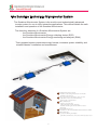
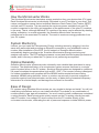
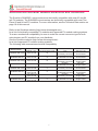
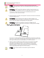
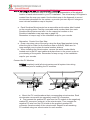
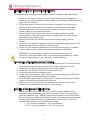
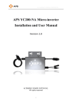
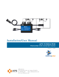
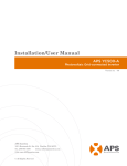
SUN250G
SUN500G
Installation and Operations Manual
SUN250G
SUN500G
www.chinesegrid.com
2013-8-1 All rights reserved
1
Contact Information
ADDRESS: Block 5, Lingyun Industrial Park, No.1177,Lingyun Road,
Ningbo National Hi-Tech Zone Ningbo,zhejiang,China.
Post:315000
TEL:+86-574-86699988
FAX:+86-574-86698369
Contact: Mr. Alan Wu
E-MAIL: [email protected]
Mob: +86-13738871588
Contact: Ms. Jingle Bai
E-MAIL: [email protected]
2
Table of Contents
Important Safety Information ------------------------------------------------------------------------------Read this First ---------------------------------------------------------------------------------------Safety Instructions ---------------------------------------------------------------------------------The Sunshine Microinverter System -------------------------------------------------------------------How the Microinverter Works --------------------------------------------------------------------System Monitoring -------------------------------------------------------------------------Optimal Reliability -------------------------------------------------------------------------Microinverter Models SUN250G and SUN500G --------------------------------------------Sunshine Microinverter Installation ----------------------------------------------------------------------Parts Included ---------------------------------------------------------------------------------------Other Parts and Tools Required ------------------------------------------------------------------Lightning Surge Suppression ---------------------------------------------------------------------Installation Procedure ------------------------------------------------------------------------------Step 1 - Install the AC Branch Circuit Junction Box -----------------------------------------Step 2 - Attach the Microinverters to the Racking -------------------------------------------Step 3 - Connect the Microinverter Wiring Harnesses -------------------------------------Step 4 – Ground the System ----------------------------------------------------------------------Step 5 – Complete the Map and Connect the PV Modules -------------------------------Complete the Sunshine Map -------------------------------------------------------------Alternative: Create Your Own Map ----------------------------------------------------Connect the PV Modules -----------------------------------------------------------------Step 6 – Build the Virtual Array -------------------------------------------------------------------Commissioning ------------------------------------------------------------------------------------------------Operating Instructions ---------------------------------------------------------------------------------------Troubleshooting -----------------------------------------------------------------------------------------------Status LED Indications and Error Reporting --------------------------------------------------Startup LED Operation: -------------------------------------------------------------------Post-Startup LED Indications ------------------------------------------------------------Other Faults ----------------------------------------------------------------------------------Troubleshooting an Inoperable Microinverter -------------------------------------------------Disconnecting a Microinverter from the PV Module -----------------------------------------Installing a Replacement Microinverter ---------------------------------------------------------Technical Data -------------------------------------------------------------------------------------------------SUN250G-US ------------------------------------------------------------------------------------------SUN250G-US -------------------------------------------------------------------------------------------
4
4
4
5
6
6
6
7
8
8
8
8
9
10
10
11
12
13
13
13
14
14
14
14
15
15
15
15
15
17
17
17
19
20
21
Appendix ---------------------------------------------------------------------------------------------------------Sunshine Installation Map --------------------------------------------------------------------------Sample Wiring Diagram, SUN250G-208-US --------------------------------------------------Sample Wiring Diagram, SUN250G-240-US --------------------------------------------------Sample Wiring Diagram, SUN500G-208-US --------------------------------------------------Sample Wiring Diagram, SUN500G-240-US ---------------------------------------------------
22
22
23
24
25
26
3
Important Safety Information
Read this First
This manual contains important instructions to follow during installation
and maintenance of the Sunshine Microinverter.
To reduce the risk of electrical shock, and to ensure the safe installation and
operation of the Sunshine Microinverter, the following safety symbols appear
throughout this document to indicate dangerous conditions and important
safety instructions.
WARNING! This indicates a situation where failure to follow instructions may
be a safety hazard or cause equipment malfunction. Use extreme caution and
follow instructions carefully.
NOTE: This indicates information particularly important for optimal system
operation. Follow instructions closely.
Safety Instructions
WARNING: Be aware that the body of the Sunshine Microinverters is the heat
sink and can reach a temperature of 80℃ under extreme conditions. To
reduce risk of burns, do not touch.
- Perform all electrical installations in accordance with all local electrical codes and the National
Electrical Code (NEC), ANSI/NFPA 70.
- Be aware that only qualified personnel should install and/or replace Sunshine Microinverters.
- Do not attempt to repair the Sunshine Microinverter; it contains no user-serviceable parts.
If it fails, please contact Sunshine customer service to obtain an RMA number and start the
replacement process. Tampering with or opening the Sunshine Microinverter will void the
warranty.
- Before installing or using the Sunshine Microinverter, please read all instructions and cautionary
markings in the technical description and on the Sunshine Microinverter system and the PV-array.
- Connect the Sunshine Microinverter to the electrical utility grid only after receiving prior approval
from the utility company.
- Do NOT disconnect the PV module from the Sunshine Microinverter before removing AC power.
4
The Sunshine Technology Microinverter System
The Sunshine Microinverter System is the world’s most technologically advanced
inverter system for use in utility-interactive applications. This manual details the safe
installation and operation of the Sunshine Microinverter.
The three key elements of a Sunshine Microinverter System are:
- the Sunshine Microinverter
- the Sunshine Microinverter Energy collecting device (ECD)
- the Sunshine Microinverter Energy monitoring and analyzer (EMA)
This integrated system maximizes energy harvest, increases system reliability, and
simplifies design, installation and management.
1
4
3
1 Sunshine Microinverter System
- installed on the racking beneath each solar module
- maximizes energy harvest
2 AC power travels over AC wring to the load center
- performance data is also via the AC wring
- plug and play communications
3 ECD communication
- plug into same AC outlet
- collects information via the AC wring
- transmits data through a standard ethernet router to
the internet
4 Standard Ethernet Router
- information collected by the ECD is then transmitted to EMA.
5 EMA Monitoring
- provides moniforing and analysis
- performnace information can be viewed from any web browser
2
5
5
How the Microinverter Works
The Sunshine Microinverter maximizes energy production from your photovoltaic (PV) array.
Each Sunshine Microinverter is individually connected to one PV module in your array. This
unique configuration means that an individual Maximum Peak Power Point Tracker (MPPT)
controls each PV module. This insures that the maximum power available from each PV
module is exported to the utility grid regardless of the performance of the other PV modules
in the array. That is, although individual PV modules in the array may be affected by shading,
soiling, orientation, or module mismatch, the Sunshine Microinverter insures top
performance for its associated PV module. The result is maximum energy production from
your PV system.
System Monitoring
Indoors, you can install the Microinverter Energy collecting device by plugging it into the
same wire wall socket and providing an Ethernet connection to your broadband router or
modem. After installation of the ECD, the full network of Sunshine Microinverters
automatically begins reporting to the Sunshine Microinverter Energy monitoring and
analyzer web server. The ECD software presents current and historical system performance
trends, and it informs you when the PV system is not performing as expected.
Optimal Reliability
Sunshine Microinverter systems are also inherently more reliable than centralized or string
inverters. The distributed nature of a microinverter system ensures that there is no single
point of system failure in the PV system. Sunshine Microinverters are designed to operate at
full power at ambient temperatures as high as 65C (150F). The inverter housing is designed
for outdoor installation and complies with the NEMA6 environmental enclosure rating
standard: NEMA6 rating definition: Indoor or outdoor use primarily to provide a degree of
protection against hose-directed water, and the entry of water during occasional temporary
submersion at a limited depth, and damage from external ice formation.
Ease of Design
PV systems using Sunshine Microinverters are very simple to design and install. You will not
need string calculations, and you can install individual PV modules in any combination of
module quantity, type, age and orientation. You won’t need to install cumbersome centralized
or string inverters. Each microinverter quickly mounts on the PV racking, directly beneath
each PV module. Low voltage DC wires connect from the PV module directly to the
co-located microinverter, eliminating the risk of personnel exposure to lethal 600Vdc power.
6
Sunshine Microinverter Models SUN250G and SUN500G
The Sunshine SUN250G microinverters are electrically compatible with most 60 and 84
cell PV modules. The SUN500G microinverters are electrically compatible with most Two
Piece 60 and 84 cell PV modules. For more information, see the Technical Data section on
page 19 of this manual.
Refer to the Sunshine website (http://www.chinesegrid.com)
for a list of electrically compatible PV modules and approved PV module racking systems.
To ensure mechanical compatibility, be sure to order the correct connector type for both
microinverter and PV module from your distributor.
See the Sunshine website (http://www.chinesegrid.com)
for a list of approved PV module racking systems.
The following table summarizes electrical compatibility.
Model Number
Works with PV
Module Type
Maximum Microinverters
per AC branch circuit
SUN250G-208-US-R
60 to 90 cell
14
SUN250G-208-US
60 to 90 cell
14
SUN250G-240-US-R
60 to 90 cell
14
SUN250G-240-US
60 to 90 cell
14
SUN500G-208-US-R
SUN500G-208-US
SUN500G-240-US-R
SUN500G-240-US
Two piece of
60 to 90 cell
Two piece of
60 to 90 cell
Two piece of
60 to 90 cell
Two piece of
60 to 90 cell
9
9
9
9
7
Module Connector
Type
DC:MC4
AC:Directly connected
DC:MC4
AC:Wieland RST 25i3
DC:MC4
AC:Directly connected
DC:MC4
AC:Wieland RST 25i3
DC:MC4
AC:Directly connected
DC:MC4
AC:Wieland RST 25i3
DC:MC4
AC:Directly connected
DC:MC4
AC:Wieland RST 25i3
Works with
Service Type
208 VAC
Three Phase
208 VAC
Three Phase
240 VAC
Single Phase
240 VAC
Single Phase
208 VAC
Three Phase
208 VAC
Three Phase
240 VAC
Single Phase
240 VAC
Single Phase
Sunshine Microinverter Installation
Follow the instructions in this section to install Sunshine SUN250G and SUN500G
Microinverters.
WARNING: Before installing the Sunshine Microinverter, read all instructions
and cautionary markings in the user manual, on the Sunshine Microinverter,
and on the photovoltaic array.
WARNING: Perform all electrical installations in accordance with all local
electrical codes and the National Electrical Code (NEC), ANSI/NFPA 70.
in US or the Canadian Electrical Code (CEC) in Canada.
WARNING: Connect the Sunshine Microinverter to the electrical utility grid
only after receiving prior approval from the utility company.
WARNING: Be aware that only qualified personnel should connect the
Sunshine Microinverter to the electrical utility grid.
WARNING: Be aware that installation of this equipment includes risk of
electric shock. Normally grounded conductors may be ungrounded and
energized when a ground fault is indicated.
WARNING:This unit is provided with fixed trip limits and shallnot be
aggregated above 30 kW on a single Point of Common Connection
Parts Included
In addition to the microinverters, PV modules, racking, and associated hardware,
you’ll need the microinverter installation kit. This kit includes the following items
- Protective end cap
- Mounting Bracket (adapter plate)
- AC interconnect cable, 6 foot length
Other Parts and Tools Required
In addition to your PV array and its associated hardware, you will need to provide
the following:
- Junction box
- Continuous grounding conductor, grounding washers
- Number 2 Phillips screwdriver
- Sockets, wrenches for mounting hardware
- Torque wrench
- Mounting hardware suitable for module racking
Lightning Surge Suppression
In some areas, the statistical frequency of lightning strikes near a PV installation is
high enough that lightning protection should be installed as part of an Sunshine
system. In areas with lighting flashes greater than 8.0 per square mile per year, the
following protection device is recommended. It has been tested to ensure that it
does not interfere with power line communications.
8
Installation Procedure
Installing the Sunshine Microinverter System involves several key steps:
1. Measuring service and Installing the AC branch circuit junction box
2. Attaching the Sunshine Microinverters to the racking
3. Connecting the Sunshine Microinverter wiring harnesses
4. Grounding the system
5. Completing the Sunshine installation map and Connecting the PV modules
Each of the detailed installation steps in the following sections is numerically
referenced in the installation diagram below.
WARNING: DO NOT connect Sunshine Microinverters to the utility grid or
energize the AC circuit(s) until you have completed all of the installation
procedures as described in the following sections.
9
Step 1 - Install the AC Branch Circuit Junction Box
1. Measure service entrance conductors to confirm AC service at the site.
Acceptable ranges are shown in the table below:
2. Mount the Sunshine Adapter Plate at a suitable location on the PV racking
system (typically at the end of a row of modules).
3. Install an appropriate junction box with adapter plate.
WARNING: Only use electrical system components approved for wet locations.
4. Connect the open wire end of the Sunshine AC interconnect cable into the
junction box using an appropriate gland or strain relief fitting. The AC
interconnect cable requires a strain relief connector with an opening of 3/8
inches in diameter.
Step 2 - Attach the Microinverters to the Racking
system.
a. Mark the approximate centers of each PV module on the racking
Evaluate the location of the microinverter with respect to the PV module
junction box or any other obstructions.
WARNING: Allow
a minimum of 0.75 inches between the top of the roof
and the bottom of the microinverter. We also recommend that you allow
0.50 inches between the back of the PV module and the top of the inverter.
Do not mount the microinverter in a location that allows long-term
exposure to direct sunlight.
b. If using grounding washers (e.g., WEEB) to ground the microinverter
chassis to the PV module racking, choose a grounding washer that is
approved for the racking manufacturer. Install a minimum of one
grounding washer per microinverter. Torque the microinverter fasteners to
the values listed below.
-1/4°± mounting hardware(R) 45 inlbs minimum
-5/16°± mounting hardware(R) 80 inlbs minimum
10
Step 3 - Connect the Microinverter Wiring Harnesses
Each microinverter comes with one 3-pin bulkhead receptacle (or short pigtail)
and one 70-inch AC wire harness with multi-pin connectors. (The DC input wires
are approximately six inches long and are terminated with single pole
connectors.) The AC connectors are oppositely sexed, so that multiple inverters
can be connected to form one continuous AC branch circuit. When you perform
this step, refer to the wiring diagram for your microinverter model. These
diagrams are located in the Appendix of this manual.
a. Orient the first microinverter in each branch with its male connector facing
the junction box. The junction box AC interconnect cable has a female
connector. The microinverter can be mounted with either side facing up to
accommodate cable routing. Connect the first microinverter to the AC
interconnect cable. All AC interconnect cables have three conductors. Wire
them as follows depending on your microinverter model:
L1
L2
L1
L2
b.Plug the AC connector of the first microinverter into the connector of the next
microinverter, and so forth, to form a continuous AC branch circuit.
Please check the microinverter rating label for the maximum allowable
number of microinverters on one AC branch circuit.
11
NOTE: The AC and DC connectors of each microinverter have been
evaluated and approved for use as the load break disconnect as required
by the NEC.
WARNING: Do NOT exceed the maximum number of microinverters in an
AC branch circuit, as displayed on the unit-rating label. Each microinverter
AC branch circuit must be sourced from a dedicated branch circuit
protected by a 25A maximum breaker.
c. Install a protective end cap on the open AC connector of the last microinverter
in the AC branch circuit.
WARNING: Make sure protective end caps have been installed on all
unused AC connectors. Unused AC microinverter wire harness connectors
are live when the system is energized by the utility system.
WARNING: Size the AC wire gauge to account for voltage drop. All
components of system wiring must be considered, including internal voltage
Step 4 – Ground the System
If you are not using grounding washers to ground the microinverter chassis as
described in step 2, follow the step below. Each Sunshine Microinverter comes
with a ground clip that can accommodate a 6-10 AWG conductor.
a. Route a continuous GEC through each of the microinverters to the NEC
approved AC grounding electrode. The racking and module could be
grounded to this conductor using a crimp connection. An alternative
method would be to connect the microinverter to the grounded racking
using a grounding washer approved for the racking.
NOTE: The AC output neutral is not bonded to ground inside the
microinverter.
12
Step 5 – Complete the Map and Connect the PV Modules
The Sunshine Installation Map is a diagrammatic representation of the physical
location of each microinverter in your PV installation. The virtual array in Enlighten is
created from the map you create. Use the blank map in the Appendix to record
microinverter placement for the system, or provide your own layout if a larger or
more intricate installation map is required.
a. Each Sunshine Microinverter has a removable serial number label located
on the mounting plate. Peel the removable serial number label from each
Sunshine Microinverter and affix it to the respective location on the
Sunshine installation map (see map on page 24).
Remember to keep a copy of the installation map for your records.
Alternative: Create Your Own Map
a. Draw a top-down view of the array using the Array Map template (using
either the grid on Side A or the freeform area on Side B). Make sure to
leave enough room to place the serial number stickers.
b. When installing the microinverters, remove the serial number labels
located next to the DC input cables and place them in the correct order on
your drawing of the system. Remember to keep a copy of the installation
map for your records.
Connect the PV Modules
NOTE: Completely install all microinverters and all system inter-wiring
connections prior to installing the PV modules.
a. Mount the PV modules above their corresponding microinverters. Each
microinverter comes with two oppositely sexed DC connectors.
b. First connect the positive DC wire from the PV module to the negatively
marked DC connector (male pin) of the microinverter. Then connect the
negative DC wire from the PV module to the positively marked DC
connector (female socket) of the microinverter. Repeat for all remaining
PV modules using one microinverter for each module. .
13
Step 6 – Build the Virtual Array
In this step, you will create the virtual array in EMA from the map you created
in the last step. Once the virtual array is built, EMA displays a graphic
representation of the PV system. It also shows detailed current and historical
performance information.
Commissioning
WARNING: Connect the Sunshine Microinverter to the electrical utility grid
only after receiving prior approval from the utility company.
WARNING: Be aware that only qualified personnel must connect the
Sunshine Microinverter to the electrical utility grid.
WARNING: Ensure that all AC and DC wiring is correct. Ensure that none
of the AC and DC wires are pinched or damaged. Ensure that all junction
boxes are properly closed.
NOTE: The Status LED of each microinverter will blink Red one times like
heartbeat to indicate normal start-up operation one minute after DC power is
applied.
To commission the Sunshine Microinverter PV system:
1. Turn ON the AC disconnect or circuit breaker on each microinverter AC
branch circuit.
2. Turn ON the main utility-grid AC circuit breaker. Your system will start
producing power after a one-minute wait time.
3. The Sunshine Microinverters will start to send performance data over the
power lines to the ECD. The time required for all the microinverters in
the system to report to the ECD will vary with the number of microinverters
in the system. The first units should be detected within 5 minutes but the
entire system could take hours to detect. Please refer to the ECD Installation
and Operation Manual for information on the ECD
Operating Instructions
The Sunshine microinverter is powered on when sufficient DC voltage from the
module is applied. The status LED will flash Red one times like heartbeat one
minute after DC power is applied. These Red blinks indicate proper start–up.
NOTE: This inverter must be used with an external GFDI device as required
by the Article 690 of the National Electrical Code for the installation location.
You can also verify proper operation of the Sunshine Microinverters via the
ECD. See the ECD Communications Gateway Installation and Operation
Manual for more information.
14
Troubleshooting
Adhere to all the safety measures described throughout this manual. Qualified
personnel can use the following troubleshooting steps if the PV system does
not operate correctly.
WARNING: Do not attempt to repair the Sunshine Microinverter; it contains no
user-serviceable parts. If it fails, please contact Sunshine customer service to
obtain an RMA number and start the replacement process.
Status LED Indications and Error Reporting
Each Sunshine microinverter has an LED that indicates status as follows:
Startup LED Operation:
One minute after DC power is first applied to the microinverter, One short
Red blinks indicate a successful microinverter startup sequence. be equal or
greater than Two short red blinks after DC power is first applied to the
microinverter indicate a failure during microinverter startup.
Post-Startup LED Indications:
Flashing Blue LED slowly means produce the power.Blue LED flashes said
the frequency of the power of the state, the faster the flashing means the
greater power.
Other Faults:
All other faults can reported to the ECD or Red LED flash times. Refer to the
ECD Installation and Operation Manual for a list of additional faults and
troubleshooting procedures.
a.Red LED falsh two times means Error of the PV input voltage
Please check the microinverter input voltage is fit the PV output
voltage
b.Red LED falsh three times means Error of the Power grid voltage
or frequency.
Please check the inverter output voltage frequency is in line with
the local grid
WARNING: Be aware that only qualified personnel should troubleshoot the PV
array or the Sunshine Microinverter.
WARNING: Never disconnect the DC wire connectors under load. Ensure that
no current is flowing in the DC wires prior to disconnecting. An opaque
covering may be used to cover the module prior to disconnecting the module.
WARNING: Always disconnect AC power before disconnecting the PV
module wires from the Sunshine Microinverter. The AC connector of the
first microinverter in a branch circuit is suitable as a disconnecting means
once the AC branch circuit breaker in the load center has been opened.
15
WARNING: The Sunshine Microinverters are powered by DC power from
the PV modules. Make sure you disconnect the DC connections and
reconnect DC power to watch for the six short LED blinks one minute after
DC is applied.
16
Troubleshooting an Inoperable Microinverter
To troubleshoot an inoperable microinverter, follow the steps in the order shown:
1. Check the connection to the utility grid. Verify that the utility voltage and
frequency are within allowable ranges shown in the Technical Data section on
page 19 of this manual.
2. Verify utility power is present at the inverter in question by removing AC,
then DC power. Never disconnect the DC wires while the microinverter
is producing power. Re-connect the DC module connectors. After one
minute, watch for one short LED blinks.
3. Check the AC branch circuit interconnection harness between all the
microinverters. Verify that each inverter is energized by the utility grid as
described in the previous step.
4. Make sure that any AC disconnects are functioning properly and are
closed.
5. Verify the PV module DC voltage is within the allowable range shown in the
Technical Data section on page 19 of this manual.
6. Check the DC connections between the microinverter and the PV module.
7. If the problem persists, please call customer support at Sunshine.
WARNING: Do not attempt to repair the Sunshine Microinverter; it
contains no user-serviceable parts. If troubleshooting methods fail, please
return the microinverter to your distributor for maintenance.
Disconnecting a Microinverter from the PV Module
To ensure the microinverter is not disconnected from the PV modules under
load, adhere to the following disconnection steps in the order shown:
1. Disconnect the AC by opening the branch circuit breaker.
2. Disconnect the first AC connector in the branch circuit.
3. Cover the module with an opaque cover.
4. Using a DC current probe, verify there is no current flowing in the DC wires
between the PV module and the microinverter.
5. Care should be taken when measuring DC currents, most clamp-on meters
must be zeroed first and tend to drift with time.
6. Disconnect the PV module DC wire connectors from the microinverter.
7. Remove the microinverter from the PV array racking.
Installing a Replacement Microinverter
1. Attach the replacement microinverter to the PV module racking using
hardware recommended by your module racking vendor. If you are using
grounding washers (e.g., WEEB) to ground the chassis of the microinverter,
the old grounding washer should be discarded, and a new grounding washer
must be used when installing the replacement microinverter. Torque the
microinverter fasteners to the values listed below:
x 1/4” mounting hardware – 45 in-lbs minimum
x 5/16” mounting hardware – 80 in-lbs minimum
17
2. If you are using a grounding electrode conductor to ground the microinverter
chassis, attach the grounding electrode conductor to the microinverter ground
clamp.
3. Connect the AC cable of the replacement microinverter and the neighboring
microinverters to complete the branch circuit connections.
4. Energize the branch circuit breaker, and verify operation of the replacement
microinverter by checking the indicator light.
18
Technical Data
Be sure to verify the voltage and current specifications of your PV module
match with those of the microinverter.
WARNING: You must match the DC operating voltage range of the PV
module with the allowable input voltage range of the Sunshine
Microinverter.
WARNING: The maximum open circuit voltage of the PV module must not
exceed the specified maximum input voltage of the Sunshine Microinverter.
The output voltage and current of the PV module depends on the quantity, size
and temperature of the PV cells, as well as the solar insolation on each cell.
The highest PV module output voltage occurs when the temperature of the
cells is the lowest and the module is at open circuit (not operating). The
maximum short circuit current rating of the module must be equal to or less
than the maximum input DC short circuit current rating of the microinverter.
19
MICROINVERTER TECHNICAL DATA SUN250G-US
60 to 90 Cell Modules
INPUT DATA (DC)
SUN-250G-US
Recommended input power (STC)
210 - 300 W
Maximum input DC voltage
60 V
Peak power tracking voltage
25 V - 55 V
Operating range
20 V - 55 V
Min/Max start voltage
25 V / 60 V
Max DC short circuit current
13 A
Max input current
10.4 A
OUTPUT DATA (AC)
@208 VAC
@240 VAC
Peak output power
250 W
250 W
Maximum output power
225 W
Nominal output current
1000mA
973mA
Nominal voltage/range
208V/183V-228V
240V/211V-264V
Nominal frequency/range
60.0/59.3-60.5 Hz
60.0/59.3-60.5 Hz
Extended frequency range
60.0/59.3-60.5 Hz
60.0/59.3-60.5 Hz
Power factor
>0.95
Maximum units per branch
14
14
EFFICIENCY
CEC weighted efficiency, 240 VAC
94.5 %
CEC weighted efficiency, 208 VAC
94.0 %
Peak inverter efficiency
95.0 %
Static MPPT efficiency
99.0 %
Night time power consumption
50 mW
MECHANICAL DATA
Ambient temperature range
-40℃ to +65℃
Dimensions (WxHxD)
215 mm x 137 mm x 30 mm(without mounting bracket)
Weight
2.0 kg
Cooling
Natural convection - No fans
Enclosure environmental rating
Outdoor - NEMA 6
FEATURES
Compatibility
Compatible with 60-82 cell PV modules.
Communication
Power line
Compliance
UL1741/IEEE1547
CAN/CSA-C22.2 NO. 107.1
Warranty
25years
20
MICROINVERTER TECHNICAL DATA SUN500G-US
60 to 90 Cell Modules
INPUT DATA (DC)
SUN-500G-US
Recommended input power (STC)
210 - 300 W(two piece)
Maximum input DC voltage
60 V
Peak power tracking voltage
25 V - 55 V
Operating range
20 V - 55 V
Min/Max start voltage
25 V / 60 V
Max DC short circuit current
13 A
Max input current
10.4 A
OUTPUT DATA (AC)
@208 VAC
@240 VAC
Peak output power
500 W
500 W
Maximum output power
450 W
450 W
Nominal output current
2163mA
1875mA
Nominal voltage/range
208V/184V-228V
240V/211V-264V
Nominal frequency/range
60.0/59.3-60.5 Hz
60.0/59.3-60.5 Hz
Extended frequency range
60.0/59.3-60.5 Hz
60.0/59.3-60.5 Hz
Power factor
>0.95
>0.95
Maximum units per branch
14
14
EFFICIENCY
CEC weighted efficiency, 240 VAC
94.5%
CEC weighted efficiency, 208 VAC
94.0%
Peak inverter efficiency
95.0%
Static MPPT efficiency (weighted, reference EN50530)
99.0 %
Night time power consumption
50 mW
MECHANICAL DATA
Ambient temperature range
-40℃ to +65℃
Dimensions (WxHxD)
230 mm x 165 mm x 30 mm (without mounting bracket)
Weight
2.5 kg
Cooling
Natural convection - No fans
Enclosure environmental rating
Outdoor - NEMA 6
FEATURES
Compatibility
Compatible with 60-82 cell PV modules.
Communication
Power line
Compliance
UL1741/IEEE1547
CAN/CSA-C22.2 NO. 107.1
Warranty
25years
21
22
No.
No.
F
No.
No.
E
No.
No.
D
No.
No.
C
No.
No.
B
No.
No.
A
12
1
12
1
12
1
12
1
12
1
12
1
Panel Group:
Azimuth:
Tilt:
sheet___of____
13
2
13
2
13
2
13
2
13
2
13
2
14
3
14
3
14
3
14
3
14
3
14
3
15
4
15
4
15
4
15
4
15
4
15
4
16
5
16
5
16
5
16
5
16
5
16
5
18
7
18
7
18
7
18
7
18
7
18
7
To Sheet______↓
17
6
17
6
17
6
17
6
17
6
17
6
To Sheet______↑
8
8
8
8
8
8
Sunshine Installation Map
9
9
9
9
9
9
10
10
10
10
10
10
11
11
11
11
11
11
Appendix
23
meter
JUNCTION
BOX
GROUND
BLACK L2
RED L1
YELLOW NEUTRAL
Sunshine
Sunshine
Sunshine
ECD
Sunshine
Sunshine
Sunshine
MAX 14 SUN250G
MAX 14 SUN250G
ETHERNET CABLE
TO BROADBAND ROUTER
Sunshine
Sunshine
Sunshine
MAX 14 SUN250G
Sample Wiring Diagram SUN250G-240-US
Sunshine
Sunshine
Sunshine
24
meter
JUNCTION
BOX
GROUND
BLACK L2
RED L1
YELLOW NEUTRAL
Sunshine
Sunshine
Sunshine
ECD
Sunshine
Sunshine
Sunshine
MAX 14 SUN250G
MAX 14 SUN250G
ETHERNET CABLE
TO BROADBAND ROUTER
Sunshine
Sunshine
Sunshine
MAX 14 SUN250G
Sample Wiring Diagram SUN250G-208-US
Sunshine
Sunshine
Sunshine
25
meter
JUNCTION
BOX
GROUND
BLACK L2
RED L1
YELLOW NEUTRAL
ECD
Sunshine
Sunshine
Sunshine
ETHERNET CABLE
TO BROADBAND ROUTER
Sunshine
Sunshine
Sunshine
Sample Wiring Diagram SUN500G-208-US
Sunshine
MAX 9 SUN500G
Sunshine
MAX 9 SUN500G
Sunshine
MAX 9 SUN500G
26
meter
JUNCTION
BOX
GROUND
BLACK L2
RED L1
YELLOW NEUTRAL
ECD
Sunshine
Sunshine
Sunshine
ETHERNET CABLE
TO BROADBAND ROUTER
Sunshine
Sunshine
Sunshine
Sample Wiring Diagram SUN500G-240-US
Sunshine
MAX 9 SUN500G
Sunshine
MAX 9 SUN500G
Sunshine
MAX 9 SUN500G