1
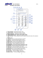
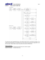
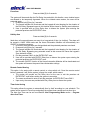
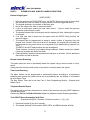
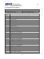
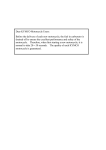
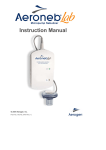
-AL2000 ALARM SYSTEM USER MANUALV1.2
AL2000 USER MANUAL
V1.2
Table of Content
Part I
Part II
Part III
Part IV
Part V
Part VI
Part VII
Introduction
Knowing Your Keypad
Call In/Out Function
Arming Your System
• Away Arm
• Day Arm
• Night Arm
• Force Arm
• Holiday Arm
• Remote Control Arming
• Timer Auto Arming
• Telephone Remote Arm
Disarm, Bypass, & Miscellaneous Functions
• Disarm Using Keypad
• Remote Control Disarming
• Timer Auto Disarming
• Telephone Remote Disarm
• Turn ON/OFF Home Automation (H/A) Point
• Bypass Zone
• Delete Bypass Zone
• System Troubleshoot
• Chime Mode
• View Memory
• Turning On/Off Keypad Sound
Emergency Situation
• Fire Mode
• Panic Mode
• Medical Mode
• Duress Code
User Programming Mode
• User Programming Code Summary
• Enter User Programming Mode
• Exit User Programming Mode
• Program New & Changing Existing User Code(s)
• Erase User Code
• Program Duress Code
• Real Time Clock Setting
• Auto Arm Time Setting
• Auto Disarm Time Setting
• Program H/A Auto ON Time
• Program H/A Auto OFF Time
• Program Telephone Number
1
3
4
5
6
6
6
7
7
7
7
8
9
9
9
9
9
10
10
10
11
11
11
12
12
12
12
13
14
14
14
14
15
15
15
15
15
16
16
AL2000 USER MANUAL
Part VIII
V1.2
System Testing
• Walk Test
• CMS Test
• Siren Test
• Strobe Light Test
• Battery Test
17
17
17
17
18
2
AL2000 USER MANUAL
PART I
V1.2
INTRODUCTION
Thank you for purchasing ELOCK security product, the total security solution that you can trust.
The AL2000 alarm panel is intended for basic yet optimal security assurance for you and your
family. It is easy to install, easy to use and easy to maintain. Just follow the instructions in this
manual to fully utilize the operations of this device and optimize your security.
Your security system consists of a main control panel, one or more keypads, eight 2.2kΩ
resistors, one jumper cap, one 2A 250V fuse, two Philips screws, one 240V to 15V step-down
transformer, an installer manual and a user manual. The main control panel is contained inside
an enclosure along with the components.
However, the AL2000 does not 100% guarantee the safety against burglary, fire or other losses.
Any alarm systems are subjected to failure due to variety of reasons. Hence, please be noted
that:
•
•
•
•
•
•
•
The intruders may be able to gain access to your property through unprotected premises,
or being able to bypass the alarm system by any possible means.
The security system may seize functioning without power supply, i.e. AC power supply
being cut off, back-up power supply (battery) is missing, dead or improperly installed.
The alarm device may not be able to alert people if it is being set up on the other side of
closed or partly closed premises.
Transmission of signal is done using telephone line transmission, hence any form of
sabotage on the telephone line or the control station may render the device useless.
Smoke detector may not be able to sense a fire hazard if the smoke does not “reach” the
detector.
The alarm may not function properly if it is not maintained accordingly. Please test your
alarm on weekly basis to ensure that the systems are functioning.
Please subscribe or continue to subscribe to insurance since the alarm panel DO NOT
100% guarantees your safety.
IMPORTANT:
It is crucial that the AL2000 is being tested out frequently (weekly) to ensure that the device is
working properly at all time. The run-test procedure can be done by referring to the steps
provided in PART VIII of the user manual. If the device is not working accordingly, kindly contact
your system installer for troubleshooting and services.
3
AL2000 USER MANUAL
PART II
V1.2
KNOWING YOUR KEYPAD
1.
2.
3.
4.
5.
6.
Power Indicator – light up when power is ON
Armed Indicator – light up when system is armed
Memory Indicator – will flash when alarm triggered
Service Indicator – light up when system require service
Keypad Lock Indicator – light up when keypad is locked
Zone Indicators – light up when the zone is selected, show the status of the selected
zone
7. Number Keys
8. Away Arm – this key will activate Away Arm function
9. Day Arm – this key will activate Day Arm function
10. Night Arm – this key will activate Night Arm function
11. Bypass Zone – this key will trigger Bypass mode
12. Force Arm – this key will trigger Force Arm mode
13. Service Key – this key will activate Service mode
14. View Memory – this key will activate View Memory mode
15. H/A Zone – this key will activate Home Automation mode
16. Chime Zone – this key will trigger Chime mode
17. Clear Key – this key will clear or cancel undesired entries
18. Holiday Mode – this key will trigger Holiday mode
19. Enter Key – this key will confirm commands entered
20. Fire Alarm – This key will trigger Fire Alarm
21. Panic Alarm – This key will trigger Panic Alarm
22. Medical Alarm – This key will trigger Medical Alarm
4
AL2000 USER MANUAL
PART III
V1.2
CALL IN/OUT FUNCTION
Chart: Call In/ Call Out Function Chart
The previous chart illustrated the flow of the alarm panel’s Call In and Call Out function. The
system will automatically cut off telephone line if the user did not provide the appropriate code
for more than 3 times or did not key in any codes for more than 60 seconds.
System Indications:
2 short beeps:
Multiple fast beeps:
Indicates successful entry into a menu or option.
Indicates false entry.
5
AL2000 USER MANUAL
PART IV
V1.2
ARMING YOUR SYSTEM
Away Arm
[USER CODE]
or
Press and hold [1] for 2 seconds
Ideal when all the occupants are out, leaving the premises empty. The system will provide users
with enter or exit delay time to allow the user to enter or exit the premises ONLY via the
ENTRY/EXIT zone. Once the delay time is up, the premises will be armed.
1. Ensure all zone indicators are distinguished and the protected premises are closed.
2. Press [ * ] key to cancel unintended operations.
3. Key in the 4-digits user code. For wrong entry, press [ * ] key and re-enter the code. The
system will arm once the correct user code is entered.
4. The Armed Indicator will illuminate and the keypad will project beeping signals in the
duration of Exit Delay. Bypassing any protected zones at this moment will trigger the
alarm.
5. Exit the premises ONLY via the ENTRY/EXIT zone.
6. The Away Arm can also be activated by simply press and hold [1] key for 2 seconds.
7. User will be provided with ENTRY Delay time to disarm the system upon entering the
protected premises via ENTRY/EXIT zone.
Day Arm
Press and hold [2] for 2 seconds
Ideal for Day time protection while users remained in the premises, the system will be armed
instantly with the exclusion of Day Stay zones (if applied).
1. Ensure all zone indicators are distinguished and the protected premises are closed.
2. DO NOT open the ENTRY/EXIT zone.
3. Press and hold [2] key for 2 seconds.
4. Armed Indicator will illuminate and the keypad will project 2 beeping signals as armed
confirmation.
5. Any Day Stay Zones will be automatically bypassed.
6. User will be given a delay time to disarm the system upon entering the protected
premises via EXIT/ENTRY zone.
Night Arm
Press and hold [3] for 2 seconds
Ideal for Night time protection while users remained in the premises, the system will be armed
instantly with the exclusion of Night Stay zones (if applied).
1. Ensure all zone indicators are distinguished and the protected premises are closed.
2. DO NOT open the ENTRY/EXIT zone.
3. Press and hold [3] key for 2 seconds.
4. Armed Indicator will illuminate and the keypad will project 2 beeping signals as armed
confirmation.
5. Any Night Stay Zones will be automatically bypassed.
6. There’s No delay time to disarm the system upon entering any protected zones. Any
violation will trigger the alarm instantly!
6
AL2000 USER MANUAL
V1.2
Force Arm
Press and hold [5] for 2 seconds
The system will be armed after the Exit Delay time and within this timeline, some violated zones
are allowed to be temporarily bypassed. When the violated zones resume, the zone will be
protected again.
1. Press and hold [5] key for 2 seconds.
2. The Armed Indicator will illuminate and the keypad will start beeping for the duration of
the Exit Delay. Bypassed zones in this timeline will be shown by flashing zone indicators.
3. User is provided with an Entry Delay time to disarm the system upon entering the
protected premises via ENTRY/EXIT zone.
Holiday Arm
Press and hold [0] for 2 seconds
Ideal when all occupants/users are away for a long period of time (ex. holiday). The alarm will
be armed in AWAY ARM mode and the Home Automation Modules will automatically turn
ON/OFF to simulate occupancy.
1. Ensure all zone indicators are distinguished and the protected premises are closed.
2. Press and hold [0] key for 2 seconds.
3. The Armed Indicator will illuminate and the keypad will start beeping for the duration of
the Exit Delay. Bypassing any protected zones at this moment will cause the keypad’s
Zone Indicator to flash.
4. Exit the premises ONLY via the ENTRY/EXIT zone.
5. User will be provided with ENTRY Delay time to disarm the system upon entering the
protected premises via ENTRY/EXIT zone.
6. The random ON/OFF function of the Home Automation Modules will be deactivated and
the system will resume the preset Home Automation settings.
Remote Control Arming
This option is for arming with a remote control or a key-switch unit. Once the remote control
button is pressed, it will set the system in Away Arm mode, which means:
• The system will provide an Exit Delay time for the user to exit the premises via
ENTRY/EXIT zone before setting the system to arm state.
• The users are allowed to enter or exit the premises via ENTRY/EXIT zone ONLY.
• Upon entry, the users are provided with Entry Delay time to disarm the system.
Timer Auto Arming
This option allows the system to automatically Arm by itself according to a set schedule. The
system will be armed in Force Arm mode when the system timer reaches an Auto Arm time.
The Auto Arm Timer can be set from Part VI: User Programming Mode section – Program
Auto Arm Timer.
7
AL2000 USER MANUAL
V1.2
Telephone Remote Arm
This function allows the user to remotely arm your facilities outside of the premises using any
DTMF telephone or GSM hand phone.
The system will be armed in Force Arm mode when the user enters a valid User Code via hand
phone or telephone. Please refer Part III: Call In/Out Function chapter for telephone remote
arming procedure.
The telephone number can be set from Part VII: User Programming Mode section – Program
Telephone Number.
8
AL2000 USER MANUAL
PART V
V1.2
DISARM, BYPASS, & MISCELLANEOUS FUNCTIONS
Disarm Using Keypad
[USER CODE]
1. Enter the premises via ENTRY/EXIT zone, the ENTRY Delay time begins to count down
the moment this zone is violated. (Entering via other zones will trigger the alarm!)
2. The keypad will beep in the duration of the delay time.
3. Key in the 4-digits user code to disarm the system.
4. If error is made upon entering the user code, press [ * ] key to cancel the previous
transaction and re-enter the code.
5. The Armed Indicator light will extinguish and the beeping will stop, indicating the system
is disarmed.
6. If no valid user code is keyed into the system within the ENTRY Delay timeline, the
alarm will trigger.
7. The keypad can be programmed to accept a certain number of key-entry tries with
Keypad Lock Counter. Once the trial limit is exceeded, the keypad will be locked and
non-responsive to any other entries for a set period of time determined by Keypad Lock
Time.
The ENTRY and EXIT delay timeline can also be adjusted.
These, however, are set by your installer during installation. Please contact your installer
if there are changes that wish to be made.
8. Flashing Memory Indicator indicates that there had been an intrusion. Call for assistance,
the intruder may still be around!
Remote Control Disarming
This option allows the user to immediately disarm the system using a remote control or a keyswitch.
Simply press the remote control button or key-switch to instantly disarm the system.
Timer Auto Disarming
The alarm system can be programmed to automatically disarm according to a pre-planned
schedule same as how the system can be set to automatically arm, but instead, it is controlled
by Auto Disarm Timer.
The Auto Disarm Timer can be set from Part VI: User Programming Section – Program Auto
Disarm Timer.
Telephone Remote Disarm
The system can be remotely disarmed from outside of the premises using any DTMF telephone
or GSM hand phone.
Please refer Part III: Call In/Out Function chapter for telephone remote disarming procedure.
Turn ON/OFF Home Automation (H/A) Point
Press and hold [8] for 2 seconds + [H/A point number (1 – 8)] + [ # ]
1. Press and hold the [8] key for 2 seconds.
2. The keypad will beep 2 times and the PWR, SERV, and MEM indicators will blink.
9
AL2000 USER MANUAL
V1.2
3. Key in the H/A point number followed by [ # ] key to manually turn ON/OFF the H/A point.
Keypad will beep 2 times and the zone indicator of the H/A point will light up to indicate
the H/A point is turned ON, or turn off to indicate the H/A point is turned OFF.
4. Repeat Step 4 to turn ON/OFF other H/A points.
5. Press the [ * ] key to exit this setting mode.
Bypass Zone
Press and hold [4] for 2 seconds
A Bypass Zone is a zone that is set to allow the user to enter the premises without triggering the
alarm even when the system is armed. The Bypass Zones will be un-bypassed each time the
system is disarmed and need to be reset before the next arming session.
This setting can only be done before arming the system.
1. Press and hold the [4] key for 2 seconds.
2. The PWR, SERV and MEM Indicators will blink and keypad will beep 2 times to indicate
that the user is now entered Bypass Zone setting.
3. Key in the zone that you wish to bypass and press [ # ] key to confirm the entry. The
keypad will beep 2 times upon confirming.
4. Repeat Step 3 for other zones that wished to be bypassed.
5. To delete a Bypass zone, key in the zone that wished to be deleted and press [ # ] key to
cancel. Repeat this step for cancelation of other Bypass Zones.
6. Once done, press [ * ] key to exit the setting. The keypad will provide a long beep and
the indicators will stop blinking.
7. The Bypass Zone(s) will be shown as the blinking zone(s) on the keypad’s Zone
Indicators.
8. Once armed, these Bypass Zones are allowed for entries without triggering the alarm.
9. All Bypass Zones will be automatically un-bypassed once the system is disarmed and
should be reset before the next arming.
Delete Bypass Zone
Press and hold [4] for 2 seconds
1.
2.
3.
4.
Press and hold the [4] key for 2 seconds to access into Bypass Zone setting.
Key in the Bypass Zone that wished to be deleted and press [ # ] key to confirm the entry.
Repeat Step 2 for other Bypass Zones cancelation.
Once done, press [ * ] key to exit the setting.
System Troubleshoot
Press and hold [6] for 2 seconds
The system is equipped with troubleshooting function to monitor for possible faulty conditions.
The Service Indicator will turn ON when of the faulty condition is detected, and the indicator will
turn OFF once the problem is fixed.
1. Press and hold the [6] key for 2 seconds to access into Service menu.
2. The PWR, SERV and MEM indicators will blink and the keypad will beep two times to
indicate correct entry into the System Troubleshoot option.
3. The turned ON zone indicator(s) represent the problem(s) occurred in the system. The
zone indications are shown by the following table.
10
AL2000 USER MANUAL
Zone 1 indicator
Zone 2 indicator
Zone 3 indicator
Zone 4 indicator
Zone 5 indicator
V1.2
AC loss
Battery low voltage
Siren fail (both siren slots have to be connected
with load)
Strobe light fail
Telephone line fail
4. Press [ # ] key to exit to the main menu.
Chime Mode
Press and hold [9] for 2 seconds + [zone number] + [ # ]
The Chime Mode allows user to monitor the premises even when the system is disarmed. When
the chime zone is violated, the keypad will project beep signal WITHOUT triggering the alarm.
(All zones are set as Chime Zones by default)
1. Press and hold the [9] key for 2 seconds.
2. The keypad will beep 2 times and the PWR, SERV, and MEM indicators will blink.
3. Enter the zone that you wish to monitor as Chime Zone followed by [ # ] key.
4. Repeat Step 3 to set more zones as Chime Zones. The zones that had been
programmed as Chime Zones are indicated by the illuminated zone indicators.
5. Once Completed the entry, press [ * ] key to exit the setting.
6. To erase an existing Chime Zones, simply repeat Step 3 on existing zones. The zone
indicators will be extinguished.
View Memory
Press and hold [7] for 2 seconds
The memory provided in the system is capable of recording the most recent alarm condition.
The Memory Indicator will blink when there is an alarm triggered, and the zone being triggered
will be noted down into the keypad.
1. Press and hold the [7] key for 2 seconds. The Memory Indicator will turn ON and the
keypad will beep 2 times indicating that the user is currently in View Memory mode.
2. The zone(s) that had been trespassed or triggered will be shown on the Zone Indicator.
3. Press [ * ] key to exit.
Turning On/Off Keypad Sound
Press and hold [ # ] for 2 seconds
The beeping sounds of the keypad can be turned off/on by pressing and holding the [ # ] key for
2 seconds.
11
AL2000 USER MANUAL
PART VI
V1.2
EMERGENCY SITUATION
Fire Mode
Press and hold [F] key for 2 seconds
This function will trigger the Fire Alarm; it can also be triggered by a smoke detector that is set
as fire zone. Press this key only during emergency where immediate assistance is required.
1. Press and hold the [F] key for 2 seconds to trigger the Fire Alarm.
2. The siren will sound and the system will send a Fire Reporting Code to the central
monitoring station.
3. Enter a valid 4-digits user code to silent the alarm.
Panic Mode
Press and hold [P] key for 2 seconds
This function will trigger the Panic Alarm; it can also be triggered by any fixed or remote panic
button that had been installed. Press this key only during emergency where immediate
assistance is required.
1. Press and hold the [P] key for 2 seconds to trigger the Panic Alarm.
2. The siren will sound and the system will send a Panic Reporting Code to the central
monitoring station.
3. Enter a valid 4-digits user code to silent the alarm or it will stop automatically after the
Siren Timeout Period.
Medical Mode
Press and hold [M] key for 2 seconds
This function will trigger the Medical Alarm. Press this key only during emergency where
immediate assistance is required.
1. Press and hold the [M] key for 2 seconds to trigger the Medical Alarm.
2. The siren will sound and the system will send a Medical Reporting Code to the central
monitoring station.
3. Enter a valid 4-digits user code to silent the alarm.
Duress Code
This is a special 4-digits user code that is advisable to use under critical situation where the
user is being forced by an intruder to disarm the system.
The Duress Code will disarm the system and at the same time, sending a Duress Reporting
Code to the central monitoring station to acquire assistance.
The Duress Code can be set in Part VI: User Programming Mode section - Program Duress
Code chapter.
12
AL2000 USER MANUAL
PART VII
V1.2
USER PROGRAMMING MODE
User Programming Code Summary
Enter User Programming Mode: [ * ] + [ # ] + [ User Master Code ] + [ # ]
“Enter” Key: [ # ]
Exit Program Option/ Cancel: [ * ]
Exit User Programming Mode: [ * ] + [ * ]
Command
Address
01
02
03
04
05
06
07
08
09
10
11
12
13
14
15
16
17
18
19
20
21
22
23
24
25
26
27
28
29
30
31
32
33
34
35
Description
Set User Code 1 (User Master Code) (Default 1234)
Set User Code 2
Set User Code 3
Set User Code 4
Set User Code 5
Set User Code 6
Set User Code 7
Set User Code 8
Set User Code 9
Set User Code 10
Program Duress Code
Real-time clock setting
Set automatic arm time
Set automatic disarm time
Set ON time 1 for H/A Module
Set OFF time 1 for H/A Module
Set ON time 2 for H/A Module
Set OFF time 2 for H/A Module
Set ON time 3 for H/A Module
Set OFF time 3 for H/A Module
Set ON time 4 for H/A Module
Set OFF time 4 for H/A Module
Set ON time 5 for H/A Module
Set OFF time 5 for H/A Module
Set ON time 6 for H/A Module
Set OFF time 6 for H/A Module
Set ON time 7 for H/A Module
Set OFF time 7 for H/A Module
Set ON time 8 for H/A Module
Set OFF time 8 for H/A Module
Program telephone number 1
Program telephone number 2
Program telephone number 3
Program telephone number 4
Program telephone number 5
13
AL2000 USER MANUAL
V1.2
Enter User Programming Mode
[ * ] + [ # ] + [USER MASTER CODE] + [ # ]
1. Ensure all systems are disarmed.
2. Press [ * ] to cancel off unwanted entries.
3. Press [ # ] followed by your 4-digits User Master Code to access into User Programming
Mode. For any wrong entries, press [ * ] key to cancel off and repeat Step 3.
4. Press [ # ] key to confirm the code insertion.
5. If a false User Master Code is provided, you will hear a long beep. Repeat Step 2-4 to
key in the code.
6. The Power and Memory Indicators will blink and the keypad will beep two times if a valid
code is provided.
7. Enter Command Address according to the settings that you desire to change and
proceed with the rest of the programming procedures.
Exit User Programming Mode
[*]
1. Press [ * ] key to exit User Programming and return to normal mode.
2. The Power and Memory Indicators will stop blinking.
3. The keypad will project a long beep to indicate that you had exited the User
Programming Mode.
Program New & Changing Existing User Code(s)
[Command Address] + [New Code] + [Re-enter New Code] + [ # ]
There are 10 User Codes allowed for the system, all allocated in 10 different Command
Addresses, and the first user code (User Master Code) is set as [1234] by default.
1. Enter User Programming Mode.
2. Enter Command Address that you wish to change. There are 10 Command Addresses
allocated for User Codes (01-10).
3. Enter a 4-digit User Code that you wish to set for the system and re-enter the code as
confirmation of the code.
4. Key-in the [ # ] key once confirmed.
5. Repeat Step 2-4 for other user codes.
6. Press [ * ] key to exit this setting option, press another [ * ] to exit User Programming
Mode.
NOTE: Please ensure that any unused User Codes are erased from the system.
Erase User Code
[Command Address] + [0000] + [0000] + [ # ]
1.
2.
3.
4.
Enter User Programming Mode.
Enter Command Address that you wish to erase.
Enter [0000] and re-enter this number followed by [ # ] key to delete the User Code.
Repeat Step 2-3 to erase other User Codes.
14
AL2000 USER MANUAL
V1.2
Program Duress Code
[11] + [New Code] + [Re-enter New Code] + [ # ]
The Duress Code is for emergency usage where the user is being forced by the intruder to
disarm the system. The Duress code will send a Duress Reporting Code to the central
monitoring station for notification.
1. Enter User Programming Mode.
2. Key-in [11] to enter Program Duress Code.
3. Enter a 4-digit code follow by re-entering the code as confirmation.
4. Key-in the [ # ] key to save the data into the system.
5. Press [ * ] key to exit this setting option, press another [ * ] key to exit the User
Programming Mode.
Real Time Clock Setting
[12] + [Current Time] + [ # ]
1.
2.
3.
4.
5.
Enter User Programming Mode.
Key-in [12] to enter Real Time Clock Setting.
Key-in time in 24-hour format, e.g. 5:45pm is key-in as 1745 (i.e. 17:45).
Press [ # ] key to confirm the time setting.
Press [ * ] key to exit time setting mode, press another [ * ] key to exit User Programming
Mode.
Auto Arm Time Setting
[13] + [Auto Arm Time] + [ # ]
1.
2.
3.
4.
5.
Enter User Programming Mode.
Key-in [13] to enter Auto Arm Time Setting.
Key-in the auto arm time in 24-hour format, e.g. 5:45pm is key-in as 1745.
Press [ # ] key to confirm the setting.
Press [ * ] key to exit the setting mode, press another [ * ] key to exit User Programming
Mode.
Auto Disarm Time Setting
[14] + [Auto Disarm Time] + [ # ]
1.
2.
3.
4.
5.
Enter User Programming Mode.
Key-in [14] to enter Auto Disarm Time Setting.
Key-in the auto disarm time in 24-hour format, e.g. 5:45pm is key-in as 1745.
Press [ # ] key to confirm the setting.
Press [ * ] key to exit the setting mode, press another [ * ] key to exit User Programming
Mode.
Program H/A Auto ON Time
[15/17/19/21/23/25/27/29] + [Auto ON Time 1-8] + [ # ]
Noted that there are 8 sets of H/A modules, each modules are controlled by different set of ON
time, hence we have 8 different sets of H/A Auto ON Time setting.
1. Enter User Programming Mode.
2. Key-in [15] to gain access to first Auto ON Time setting, or
Key-in [17] to gain access to second Auto ON Time setting, or
15
AL2000 USER MANUAL
V1.2
Key-in [19] to gain access to third Auto ON Time setting, or
Key-in [21] to gain access to fourth Auto ON Time setting, or
Key-in [23] to gain access to fifth Auto ON Time setting, or
Key-in [25] to gain access to sixth Auto ON Time setting, or
Key-in [27] to gain access to seventh Auto ON Time setting, or
Key-in [29] to gain access to eighth Auto ON Time setting.
3. Key-in the auto ON time in 24-hour format, e.g. 5.45pm is key-in as 1745.
4. Press [ # ] key to confirm the setting.
5. Press [ * ] key to exit the setting mode, repeat Step 2 to program other auto ON time or
press another [ * ] key to exit User Programming Mode.
Program H/A Auto OFF Time
[16/18/20/22/24/26/28/30] + [Auto OFF Time 1-8] + [ # ]
Noted that there are 8 sets of H/A modules, each modules are controlled by different set of OFF
time, hence we have 8 different sets of H/A Auto OFF Time setting.
1. Enter User Programming Mode.
2. Key-in [16] to gain access to first Auto OFF Time setting.
Key-in [18] to gain access to second Auto OFF Time setting.
Key-in [20] to gain access to third Auto OFF Time setting.
Key-in [22] to gain access to fourth Auto OFF Time setting.
Key-in [24] to gain access to fifth Auto OFF Time setting.
Key-in [26] to gain access to sixth Auto OFF Time setting.
Key-in [28] to gain access to seventh Auto OFF Time setting.
Key-in [30] to gain access to eighth Auto OFF Time setting.
3. Key-in the auto OFF time in 24-hour format, e.g. 5.45pm is key in as 1745.
4. Press [ # ] key to confirm the setting.
5. Press [ * ] key to exit the setting mode, repeat Step 2 to program other auto ON time or
press another [ * ] key to exit User Programming Mode.
Program Telephone Number
[31-35] + [Phone Number 1-5] + [ # ]
This alarm system is equipped with notification function where the system will call out to user
phone to report on intrusion. If the system failed to notify the number however, the second
contact number (Telephone Number 2) will be used as back-up.
This system comes along with 1 key contact and another 4 back-up contacts at your disposal.
1. Enter User Programming Mode.
2. Key-in [31] to gain access into Program Telephone Number 1 setting.
Key-in [32] to gain access into Program Telephone Number 2 setting.
Key-in [33] to gain access into Program Telephone Number 3 setting.
Key-in [34] to gain access into Program Telephone Number 4 setting.
Key-in [35] to gain access into Program Telephone Number 5 setting.
3. Key-in telephone number (maximum of 10 digits length).
4. To delete phone number, key-in “0000000000”.
5. Press [ # ] key upon confirmation.
6. Press [ * ] key to exit this setting.
16
AL2000 USER MANUAL
PART VIII
V1.2
SYSTEM TESTING
It is important to test the system frequently to ensure the functionality and reliability of the alarm
devices equipped in the premises. Users are advised to perform the testing at least once every
3 months. If the system or any of the alarm devices are not functioning accordingly, kindly
contact your system provider for technical assistance.
Walk Test
[ * ] + [ # ] + [1] + [ # ]
The Walk Test allows user to test the functionality of the protected premises or zones.
1. Press [ * ] key to clear off any unwanted transactions.
2. Press [ # ] key follow by [1], then another [ # ] key to enter Walk Test Mode.
3. Once entered Walk Test, the PWR, ARM and SERV LED will blink.
4. Test the protected zones by invading the premises, the alarm will be triggered for 2
seconds.
5. If alarm signals are not detected upon violation of the premises, kindly consult your
system provider.
6. Press [ * ] key to exit the Walk Test Mode.
CMS Test
[ * ] + [ # ] + [2] + [ # ]
The CMS Test allows user to test the functionality of the CMS Reporting function of the alarm
system.
1. Press [ * ] key to clear off any unwanted transactions.
2. Press [ # ] key follow by [2], then another [ # ] key to enter CMS Test Mode.
3. A CMS Test Code will be sent to the central monitoring station to simulate CMS
Reporting procedure.
4. Wait 2 minutes; if CMS Reporting fails, a trouble condition will be registered to the
system.
5. Press and hold [6] key for 2 seconds to troubleshoot the condition, kindly consult your
system provider for technical assistance.
Siren Test
[ * ] + [ # ] + [3] + [ # ]
The Siren Test allows user to test the functionality of the siren.
1. Press [ * ] key to clear off any unwanted transactions.
2. Press [ # ] key follow by [3], then another [ # ] key to enter Siren Test Mode.
3. The siren will trigger for 3 seconds.
4. If no siren was heard, kindly consult your system provider.
Strobe Light Test
[ * ] + [ # ] + [4] + [ # ]
The Strobe Light Test allows user to test the functionality of the strobe light.
1. Press [ * ] key to clear off any unwanted transactions.
2. Press [ # ] key follow by [4], then another [ # ] key to enter Strobe Light Test Mode.
3. The strobe light will flash for 10 seconds.
4. If the strobe light is not showing any signals, kindly consult your system provider.
17
AL2000 USER MANUAL
V1.2
Battery Test
[ * ] + [ # ] + [5] + [ # ]
The Battery Test allows user to test the functionality of the back-up battery.
1. Press [ * ] key to clear off any unwanted transactions.
2. Press [ # ] key follow by [5], then another [ # ] key to enter Battery Test Mode.
3. Wait 10 seconds; if back-up battery fails, a trouble condition will be registered to the
system.
4. Press and hold [6] key for 2 seconds to troubleshoot the system, kindly consult your
system provider for technical assistance.
18