1
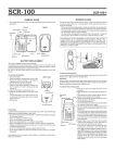
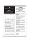
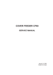
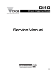
OWNER’S MANUAL Thank you for choosing a Free The Tone product. In order to take full advantage of the features and performance it provides, please read this owner’s manual thoroughly, and keep it in a safe place for future reference. Table of Contents 1. Signal Block Diagram.............................................................................................................. 4 Handling Precautions 2. Front Panel.......................................................................................................................... 5 • Never connect or disconnect plugs to/from the input/output terminals on the ARC-3 when the external device that drives speakers is powered. Doing so can cause noises and damage the speakers. • Avoid applying excessive force to the footswitches, tact switches, and phone jacks on the ARC-3. • If the unit malfunctions or behaves erratically, cease operation at once and contact your local dealer or Free The Tone directly. 3. Rear Panel.......................................................................................................................... 6 4. Basic Operation. . ................................................................................................................... 4-1 Three Operation Modes....................................................................................................... 4-2 How to Edit Presets........................................................................................................... 4-3 Edit Mode...................................................................................................................... 7 7 7 8 5. How to Use Separate Loop. . ...................................................................................................... 8 Support/Service 6. Edit Menu........................................................................................................................... 9 Contact the following for support and/or repair service. e-mail address: [email protected] 7. ARC-3’s Bank Presets & MIDI Program Change Numbers...................................................................... 13 7-1 MIDI program change numbers received at MIDI IN terminal in Bank mode.............................................. 13 7-2 M IDI program change numbers for each preset sent from ARC-3 (initial settings for MIDI Tx Global: ON)............. 13 8. Connection Examples.............................................................................................................. 14 9. Specifications....................................................................................................................... 15 SEFETY PRECAUTIONS Precautions are identified by the two types of symbols below: Caution Warning This symbol indicates that a risk of serious personal injury or This symbol indicates that a risk of death or serious personal material damage may result if precautions are ignored. injury may result if precautions are ignored. Be sure to read these precautions and the user’s manual before using this product. Caution Do not use or store the unit in environments where it will be exposed to: Extreme temperatures (direct rays of the sun, heat sources such as radiators or stoves.) High humidity or moisture. Excessive dust or sand. Excessive vibration or shock. Whenever leaving the unit unattended for long periods, be Warning Never try to disassemble, or modify the unit. Stop using the unit if you notice smoke or a strange odor coming from it and unplug the AC adapter from the outlet. Never try to repair the unit or replace parts unless so instructed by the user’s manual. For other repair or parts replacement contact your local dealer or Free The Tone. Never unplug the the AC adapter while your hands are wet. sure to unplug the AC adapter from the power source to Do not apply too much pressure or tension or place a heavy avoid creating a fire hazard. object on the power cord. Doing so may damage the power Take care not to drop the unit, and do not subject it to excessive pressure or weight. Do not press the switches on the unit with a bare foot, or unexpected injury may result. Do not use solvents (such as benzine, paint thinner) on the unit, since these may dull the finish or damage the surface. cord and create a danger of fire or electrical shock. Turn off the unit and unplug the AC adapter from the outlet and contact your local dealer or Free The Tone for repair in the case of any of the following: The power cord is damaged Foregin objects (coins, pins, etc.) or liquid enter the unit. The unit gets wet from rain or other liquid. The unit is out of order. Be careful of heat radiation from the unit. Never cover the AC adapter with cloth or other objects. Builtup heat can deform the case or cause a fire hazard. Main Features of ARC-3 Sound Quality The Free The Tone ARC-3 is based on the know-how developed from many years of building custom products for top musicians. The ARC-3 has a built-in HTS (Holistic Tonal Solution) circuit to preserve the original characteristics of a bass, guitar, effects and amp. It manages everything at the input and output, including the send and return for effects, and the signal line. Operability • The distance between the foot switches is 71.5 mm (2.81") in the vertical direction and 80 mm (3.15") in the horizontal direction, and custom foot switches are used. These short stroke switches respond quickly in order to follow even fast operation. • A Link function is provided making it possible to connect and operate two ARC-3s. • A Mute Link function makes muting control possible from an external footswitch. • A special panel is provided for changing settings or selecting presets. Operability is drastically improved by reducing the levels of edit menus as much as possible. This greatly reduces the amount of time spent editing. • The ARC-3 has functions such as the preset copy, delete and swap, and bank copy and delete, which simplify operation. • By switching the Display Mode, the MIDI program change numbers for each channel that is currently being sent can be checked at a glance. Reliability •T he LED for each footswitch is covered by a lens to prevent sweat or other moisture from entering directly into the internal circuits. Also, a felt sheet is attached to the back of the display unit. •H igh-strength molded plastic phone jacks are used to ensure safe and long term use. Others •A DI signal line, which is often required by bassists, was also taken into consideration. A terminal is provided which outputs the signal after it has passed through the HTS input circuit. The output line has a Mute switch that can be linked to the mute circuit. With this feature, the signal to both the DI output and to an amplifier can be muted simultaneously. •A Universal AC adapter, which supports voltages of 100–240 VAC, is included. • To prevent accidental operation of the control panel while playing, an AUTO LOCK function makes it possible to lock the operation buttons. The AUTO LOCK function engages automatically after 10 minutes of non-operation. Main Features Number of Effect Loops: 8 Number of Presets: 64 banks x 10 presets (total 640 presets) Control Terminals: 6 (switchable Latch or Momentary) Expression Pedal Terminal: 1 Number of MIDI Program Change Number Parallel Sends: 8 (CH1–CH8 fixed), when MIDI Tx Global is set to OFF Number of MIDI Control Change Number Parallel Sends: 8 SIGNAL BLOCK DIAGRAM FRONT PANEL PS/L switch When in PS (Preset) mode this switch is used to recall the corresponding preset. When in DIR (Direct) mode pressing this switch turns on/off the corresponding effect loop. MODE switch Used to switch the operation modes of the ARC-3. In PS (Preset) mode the PS indicator illuminates and pressing a PS/L switch recalls the corresponding preset. In DIR (Direct) mode the DIR indicator illuminates and pressing a PS/L switch turns on/off the corresponding effect loop. Pressing the MODE switch for about three seconds puts the ARC3 in Edit mode. Pressing it again exits from Edit mode to usual operation mode. BANK /STORE switch Pressing this switch in Program mode decrements the bank number. Note that changing the bank number causes the display to flash but your change will not be confirmed until you press the PS/L switch. In Direct mode this switch used to store the setting. BANK /L7 switch Pressing this switch in Program mode increments the bank number. Note that changing the bank number causes the display to flash but your change will not be confirmed until you press the PS/L switch. In Direct mode this switch turns on/off the effect loop 7 (L7). Control Panel This panel indicates preset contents and the current preset number and is used to edit parameters in Edit mode. MUTE switch Activates the mute circuit in the output to mute the signal. Mute positions (M1–M3) to be linked with this switch can be selected in Setup menu. CONTROL PANEL Multi-status LED According to the selected mode, these LEDs indicate the status currently stored in the preset. Display The numeral shown in the left two positions is the bank number. The right two positions of the display indicate the currently selected preset number. The dot labeled “MIDI SIG” illuminates when MIDI signals are being sent or received. INC/+ switch, DEC/– switch Used when changing parameters. DISP MODE (Display Mode) switch Used to change operating modes of the LED displays or Select Switches (1–6, 7/M1, 8/M2). Effect Loop LED Indicates the on/off status of each loop (L1–L8). Select Switches Used to edit or confirm the contents saved in presets. Note that the items to be selected vary according to the mode selected by the DISP MODE switch. ENTER switch Used in Edit mode to select the item to be edited or to confirm the selection. STORE switch Used when storing your change to the setting in the preset. LOCK switch Used to lock the switches on the Control Panel, preventing unintentional tampering. Holding this switch for three seconds locks the switches and the LED illuminates. Pressing the switch for three seconds again unlocks the Control Panel and the LOCK LED goes off. REAR PANEL BASIC OPERATION 4-1 Three Operation Modes The ARC-3 has the following three operation modes: • PS (Preset) Mode For recalling presets. When in this mode, the PS LED above the MODE switch illuminates. • DIR (Direct) Mode In this mode each effect loop can be turned on/off by using the corresponding footswitch. When in this mode, the DIR LED above the MODE switch illuminates. • Edit Mode Used when making detailed setup of the ARC-3. Hold down the MODE switch for three seconds to put the ARC-3 in Edit mode. 4-2 How to Edit Presets HTS-IN terminal Input terminal to the ARC-3. The signal fed to this input goes through the ARC-3’s HTS circuit and appears at HTS-OUT to be fed to effectors. HTS-OUT terminal The signal fed to HTS-IN can be sent to other signal lines from this terminal. Bassists can use this terminal as a line to feed a D.I. box. Muting of this signal line can be linked with the MUTE switch. IN-A terminal This input terminal is located just after the HTS input circuit. OUT-8(N.O) can be used as a control terminal (normally open). Note that the tip and ground in the jack are electrically connected when the loop 8 is on. LATCH/MOMENTARY CONTROL terminals (C1–C6) Latch or momentary control terminals for amplifier channel switching or on/off controlling of reverbs. Prepare a stereo plug wired for the external device to be controlled: OUT-B terminal This terminal outputs the signal that passed through the effect loops 5–7. M2 mute circuit is located just in front of this terminal. Signals at OUT-B can be muted by pressing the MUTE switch or by setting “M2:ON” in the preset. SEPARATE LOOP terminals [IN-8, S-8(N.C), R-8, OUT-8(N.O)] This is a separate loop that is electrically isolated from other loops. Use this loop when using an effector with which you cannot create intended tone if it is fed a low impedance signal (e.g., a fuzz pedal). S-8(N.C) can be used as a control terminal (normally closed) for amplifier channel switching. Note that the tip and ground in the jack are electrically connected when the loop 8 is off. Press BANK /STORE to store your selection. Stereo plug’s GND: Common ground for C1/C2 and C3/C4 Stereo plug’s Ring: Normally closed terminal, i.e. there is a connection S-5–R-7 terminals Effect loop terminals. S5–S7 send signals to effectors. R5–R7 receive signals from effectors. Press MODE to select “DIR”. Stereo plug’s Ring: C2 & C4 OUT-A terminal This terminal outputs the signal that passed through the effect loops 1–4. M1 mute circuit is located just in front of this terminal. Signals at OUT-A can be muted by pressing the MUTE switch or by setting “M1:ON” in the preset. IN-B terminal This input terminal is located just in front of the effect loop 5. • How to store Effect Loops (L1–L8) in Presets: 1 Stereo plug’s Tip: C1 & C3 Connection of C5 & C6 Control Terminals EXT OUT terminal This terminal outputs the signal that passed through the effect loops 1–4. This output is not muted even if the MUTE switch is turned on. store the setting, press the STORE switch. Your changes are not saved if you recall another preset without pressing the STORE switch. Connection of C1/C2 & C3/C4 Control Terminals S-1–R-4 terminals Effect loop terminals. S1–S4 send signals to effectors. R1–R4 receive signals from effectors. TUNER terminal Used to feed an external tuner. The signal fed to HTS-IN or IN-A appears at TUNER even when the MUTE switch is turned on. Presets in the ARC-3 can be edited very easily with the Control Panel only. When you change any contents of a preset, the display illuminates the dot LED at the right side of its lowest position. To Stereo plug’s Tip: Normally open terminal, i.e. there is no connection between the tip and ground when OFF. When ON, the tip and ground are electrically connected. between the tip and ground when OFF. When ON, the connection between Press PS/L to recall the preset to be used. Press MODE to select “PS” (the ARC-3 returns to Preset mode). Press PS/L or BANK /L7 to select the effect loop to be used. the tip and ground is lost. E1–E4 terminals (EXTERNAL SWITCH terminals) Each terminal can have a function. This assignment can be changed in Edit mode. Default settings at factory shipment are as follows: E1: PS8 (recalls preset no. 8) E2: PS9 (recalls preset no. 9) E3: PS10 (recalls preset no. 10) • How to store Effect Loops (L1–L8) in Presets: 2 Press DISP MODE to select “LOOP”. Press PS/L to recall the preset to be used. Press STORE to store your selection. E4: EXP PEDAL (plug an expression pedal and send VALUE via MIDI transmission) LINK terminal Used to connect to another ARC-3 for linked operation. Use a special DIN 7-pin cross cable. For more detailed information on this dedicated cable please contact your local dealer or Free The Tone directly. POWER DC12V IN receptacle Used to connect the dedicated AC adapter. Be sure to use the AC adapter supplied with the ARC-3. NOTE: Control change numbers to be assigned to the Select Switches 1–8 are set in Edit mode “MIDI-CSW CC#” (refer p.10). • How to store MIDI PC# (program change number) sends in Presets (1) To simply control a MIDI device by using one MIDI channel MUTE LINK terminal By connecting a momentary (unlatch) type footswitch to this terminal, the mute function can be controlled externally. MIDI IN and MIDI OUT/THRU terminals I/O terminals for MIDI signals. MIDI IN receives MIDI signals from an external MIDI device. MIDI OUT/THRU is used to feed MIDI signals to external MIDI devices. When the opertion mode of MIDI OUT/THRU has been set to “THRU”, MIDI signals received at MIDI IN pass through the ARC-3 without any changes. •H ow to store MIDI CC# (control change number) sends in Presets Press PS/L to recall the preset to be used. Press DISP MODE to select “MIDI CC#”. Press the Select Switch to choose the MIDI CC# to be used. Press STORE to store your selection. (selected from CH1–CH16) (when MIDI Tx Global is turned ON) Press PS/L to recall the preset to be used. Press DISP MODE to select “MIDI PC#”. NOTE: The MIDI program change number assigned to the selected preset is shown in the display (refer p.13). Press the Select Switch to choose the effect loop to be used. •H ow to store Control terminals (C1–C6) and signal line mutes (M1, M2) in Presets Press PS/L to recall the preset to be used. Press DISP MODE to select “CTL/MUTE”. Press the Select Switch to choose the control terminal (C1–C6) and signal line mute (M1 or M2) to be used. Press STORE to store your selection. Press INC/+ or DEC/– to set the MIDI program change number you want to send. Or select “OFF” if you do not want to send any program change number. Press STORE to store your selection. (2) To control multiple MIDI devices by using eight MIDI channels (CH1–CH8 fixed) (when MIDI Tx Global is turned OFF) Press PS/L to recall the preset to be used. Press DISP MODE to select “MIDI PC#”. NOTE: MIDI channels 1–8 are already assigned to the Select Switches 1–8. By pressing the Select Switch 1, MIDI program change number to be sent via MIDI channel 1 is shown in the display. Defalut setting is all OFF. Press the Select Switch to which the desired MIDI channel has been assigned. Press INC/+ or DEC/– to set the MIDI program change number you want to send. Or select “OFF” if you do not want to send any program change number. Press STORE to store your selection. 4-3 Edit Mode Detalied setups of the ARC-3 are done in Edit mode. Holding down the MODE switch for three seconds puts the ARC-3 in Edit mode and the display shows “MENU”. Press one of the PS/L switches to select the desired menu item. The following menu items are assigned to the PS/L switches: PS1/L1: PRESET PS2/L2: MIDI PS3/L3: SETUP PS4/L4: UTILITY When you select the menu item by pressing the corresponding PS/ L switch, the display shows the page 1 of the screen assigned to that menu. You can also recall the desired page by pressing the Select Switch in the Control Panel. To exit from Edit mode to usual operation mode, press the MODE switch. 3) To use as an input selector The separate loop can be used as an input selector to choose one of the two inputs. By turning on the loop, input 2 signal connected to the Return jack appears at the Output (OUT-8) jack. By turning off the loop, input 1 signal connected to the Input (IN-8) jack appears at the Output (OUT-8) jack. Leave the Send (S-8) jack unconnected. Signal flow when the Loop is ON Signal flow when the Loop is OFF NOTE: In Edit mode, your changes are confirmed when the ENTER switch in the Control Panel is pressed. You do not have to press the STORE switch. Input 1 (GTR/BASS) Input 2 (GTR/BASS) Output EDIT MENU Detailed setup of the ARC-3 is done in Edit mode. The following tables explain configurations available in Edit mode and how to set them. To keep this manual simple and easy to understand, some descriptions for setup procedures are simplified. HOW TO USE SEPARATE LOOP 1) To use as an effect loop If the seven loops (L1–L7) are not enough for your application, the separate loop can be used as an additional effect loop. Connect your signal to the Input (IN-8) jack and connect the Send (S-8) jack to your effector’s input. Connect the effector’s output to the Return (R-8) jack, then the Output (OUT-8) jack to the downstream device. The following terms are used in the explanations for setup procedures. • ENTER: Press the ENTER switch located on the Control Panel to confirm your selection. • Set: Press the INC/+ or DEC/– switch on the Control Panel until the desired value or item is shown in the display. • Parameter: Values or items that can be changed by users. • Default: Parameter settings configured before shipment from factory. PRESET (PS1/L1 footswitch) Select Switch Menu Signal flow when the Loop is ON Signal flow when the Loop is OFF Input Effector 1 PRESET COPY This item is used to copy the contets of a preset to another preset. How to Set [PSCP] on ENTER FROM [PRESET NUMBER] flashes Set ENTER TO [PRESET NUMBER] flashes Set ENTER Parameter: [00-01]–[63-01] (default: 00-01) Output 2 2) To use as an output selector The separate loop can be used as an output selector to choose one of the two outputs. If the loop is turned on and output 1 is selected, output 2 is muted to prevent crosstalk or noises. Conversely if the loop is turned off and output 2 is selected, output 1 is muted. Feed to the Input (IN-8) jack and connect to the input of your amplifier, etc. from the Send (S-8) jack. Leave the Return (R-8) jack unconnected. Connect the Output (OUT-8) jack to the input of another amplifier, etc. BANK COPY This item is used to copy the contents of a bank to another bank. [BKCP] on ENTER FROM [BANK NUMBER] flashes Set ENTER TO [BANK NUMBER] flashes Set ENTER Parameter: [00]–[63] (defualt: 00) 3 PRESET DELETE This item is used to delete the contents of the specified preset. [PSDL] on ENTER [PRESET NUMBER] flashes Set ENTER [DONE] Parameter: [00-01]–[63-01] (default: 00-01) Signal flow when the Loop is ON Signal flow when the Loop is OFF 4 BANK DELETE This item is used to delete the contents of the specified bank. [BKDL] on ENTER [BANK NUMBER] flashes Set ENTER [DONE] Parameter: [00]–[63] (default: 00) Input Output 1 (AMP1) Output 2 (AMP2) 5 SWAP This item is used to swap the contents of two presets. [SWAP] on ENTER [PRESET NUMBER] flashes Set ENTER [AND] [PRESET NUMBER] flashes Set ENTER [DONE] SETUP (PS3/L3 footswitch) MIDI (PS2/L2 footswitch) Select Switch Menu 1 MIDI Rx This item is used to set the MIDI receive channel. How to Set [RXCH] on ENTER [OMNI] flashes Set ENTER Select Switch Menu 1 Parameter: CH01–CH16, OMNI, OFF (default: OMNI) 2 3 MIDI Tx Global This item is used to set to send one program change number for one preset by limiting to use one MIDI transmit channel only. If set to OFF, eight MIDI channels are available. MIDI Tx This item is used to set the MIDI transmit channel. [TXGB] on ENTER [ON] flashes Set ENTER Parameter: ON, OFF (default: ON) [TXCH] on ENTER [CH01] flashes Set ENTER Parameter: CH01–CH16, OFF (default: CH01) 4 5 CSW CC# This item is used to set the MIDI control change number to be sent. Up to 8 control switches (CSW1–CSW8) can be set. MIDI control change number and MIDI channel can be set to each CSW (control switch). [CSCC] on ENTER [CSW1] on Set (param1) ENTER [OFF] flashes Set (param2) ENTER [CH01] flashes Set (param3) ENTER CSW SWITCH TYPE This item sets the operation type (LATCH or MOMENTARY) of the CSW (control switch) specified by item 4 above. [CSTP] on ENTER [CSW1] flashes Set (param1) ENTER [LTCH] flashes Set (param2) ENTER 2 LINK MODE This item is used to select the operation mode for two linked ARC-3s. When in Link mode, the preset number for the two units is always synchronized together but the contents of the presets are set individually. When in Master/Slave mode, the settings and presets on the Master unit have priority for use and the Slave unit acts as a remote controller. CAUTION: When set to Master/Slave mode, be sure to connect to the terminals (MIDI IN/OUT, EXP PEDAL, etc.) on the Master unit. [LKMD] on ENTER [LINK] flashes Set ENTER External Foot Switch Assignment This item is used to assign functions to the E1–E4 terminals on the rear panel. [EXFS] on ENTER [E1] on Set (param1) ENTER [PS8 (for E1)] flashes Set (param2) ENTER Parameter 1: CSW1–CSW8 Parameter 2: 000–120, OFF (defualt: OFF) Parameter 3: CH1–CH16 (default: CH01) Control Change Number This item is used to set the control change number assigned to each function. * This menu is used to edit CC# assigned to each function. [CCNM] on ENTER [L1] on Set (param1) [OFF] flashes Set (param2) ENTER Parameter 1: LOOP1 [L1]–LOOP8 [L8] MUTE [MUTE] MODE [MODE] EXP PEDAL [EXP] CTL1 [C1]–CTL6 [C6] MUTE1 [MT1], MUTE2 [MT2] Parameter 2: 000–120, OFF (defualt: OFF) Items with initial settings EXP PEDAL [EXP] 000–0120, OFF (defalut: 112) CTL1 [C1] 000–120, OFF (default: 113) CTL2 [C2] 000–120, OFF (default: 114) CTL3 [C3] 000–120, OFF (default: 115) CTL4 [C1] 000–120, OFF (default: 116) CTL5 [C1] 000–120, OFF (default: 117) CTL6 [C1] 000–120, OFF (default: 118) MUTE1 [MT1] 000–120, OFF (default: 119) MUTE2 [MT2] 000–120, OFF (default: 120) 7 MIDI OUT/THRU This item is used to set the operation mode of the MIDI OUT/ THRU terminal. [O/TH] on ENTER [OUT] flashes Set ENTER Parameter: OUT, THRU (defualt: OUT) Parameter: LINK, MASTER, SLAVE (default: LINK) Param1 Param2 E1: PS8 (default), L1–8, CTL1–6, MUTE1, MUTE2, CSW1–8 E2: PS9 (default), L1–8, CTL1–6, MUTE1, MUTE2, CSW1–8 E3: PS10 (default) L1–8, CTL1–6, MUTE1, MUTE2, CSW1–8 E4: EXP PEDAL (default), L1–8, CTL1–6, MUTE1, MUTE2, CSW1–8 3 Control Type This item is used to select the operation type for CONTROL 1–6 from LATCH and MOMENTARY. [CTTP] on ENTER [CTL1] on Set (param1) ENTER [LATCH] flashes Set (param2) ENTER Parameter 1: CTL1 [C1]–CTL6 [C6] Parameter 2: LATCH, MOMENTARY (default: LATCH) Parameter 1: CSW1–CSW8 Parameter 2: LATCH, MOMENTARY (default: LATCH) 6 How to Set 4 5 MUTE MODE This item is used to set the operation mode for the MUTE switch. When set to AUTO, pressing a preset switch automatically clears the mute status. When set to MANUAL, the mute status is cleared by pressing the MUTE switch again. MUTE POSITION This item is used to select the mute circuit (M1–M3) activated by turning on the MUTE switch. [MTMD] on ENTER [AUTO] flashes Set ENTER Parameter: AUTO, MANUAL (default: AUTO) [MTMD] on ENTER M1 Set (param1) ENTER [ON (for MT1)] flashes Set (param2) ENTER Parameter 1: MT1–MT3 Parameter 2: ON, OFF (default for MT1 & MT2: ON, default for MT3: OFF) 6 MUTE SW configuration This item is used to enable or disable the MUTE switch. [MTFS] on ENTER [ON] flashes Set ENTER Parameter: ON, OFF (default: ON) 7 EXP Pedal Calibration This item is used to calibrate your expression pedal. Please be sure to use an expression pedal using a 10 kΩ variable resistor. [CALB] on ENTER [Hi] flashes Set EXP pedal to max. ENTER [LOW] flashes Set EXP pedal to min. ENTER [DONE] 8 Starting number Not all of the MIDI devices use the same starting number for MIDI program change number. The ARC-3 can set the starting number in accordance with the device to be connected. [STNM] on ENTER [001] flashes Set ENTER Parameter: 1–128 [001], 0–127 [000] (default: 1–128) UTILITY (PS4/L4 footswitch) Select Switch Menu 1 2 3 4 AUTO LOCK This item is used to set the Lock function for the front panel. If the Auto Lock function is turned on and the Control Panel is left untouched for about ten minutes, the front panel switches are automatically locked out. Memory Protect This item is used to protect the settings stored in the ARC-3 from tampering. The M.PROTECT dot in the display illuminates when the protection is turned on. LED BRIGHTNESS This item is used to adjust LED brightness. If LED is too dim during outdoor performance, set this parameter to “1” (bright). PGM DUMP/LOAD This item is used to transfer the data saved in one ARC-3 to another ARC-3 or vice versa. ARC-3’S BANK PRESETS & MIDI PROGRAM CHANGE NUMBERS How to Set [LOCK] on ENTER [OFF] flashes Set ENTER 7-1 MIDI program change numbers received at MIDI IN terminal in Bank mode Parameter: ON, OFF (defualt: OFF) [PROT] on ENTER [OFF] flashes Set ENTER Parameter: OFF, ON (default: OFF) [BRIT] on ENTER [1] flashes Set ENTER Parameter: 1 = bright, 2 = standard (default: 2) Procedure for MIDI LOAD (receive) [DUMP] on ENTER [RECV] flashes ENTER [YES] flashes ENTER (wait for data to be sent) [DONE] or [ERR] [DUMP] on Procedure for MIDI DUMP (send) [DUMP] on ENTER Set to flash [SEND] ENTER [YES] flashes ENTER [01–63 in order] [DUMP] on Parameter: RECV, SEND 5 Initialize This returns the ARC-3 to its factory shipment status. [INIT] on ENTER [YES] flashes ENTER [DONE] on [INIT] on 7-2 MIDI program change numbers for each preset sent from ARC-3 (initial settings for MIDI Tx Global: ON) CONNECTION EXAMPLES SPECIFICATIONS Example 1 Basic configuration to use one amplifier with seven effectors connected in series. (Channel Switching) To AMP Control C1/C2 C3/C4 Control Example 2 A connection example for bass. The signal is sent to a D.I. box from the HTS-OUT terminal. The signal also passes the four effectors connected in series and is fed to the amplifier. To mute the signal from the HTS-OUT terminal, put the ARC-3 in Edit mode and turn on M3 in “SETUP-MUTE POSITION” (refer p. 11). Example 3 The guitar signal is divided into two independent lines just after the HTS-IN terminal. Users can program Mute functions M1 and M2 in presets to use only one of the two amplifiers or both of them. n Specifications • Input Impedance: 1 MΩ (HTS-IN) • Output Impedance: Less than 200Ω (HTS-OUT, OUT-A, OUT-B) • Power Supply: Dedicated AC adapter For USA: FA-1220D-JA For UK: FA-1220D-UK For Europe: FA-1220D-EU • Power Consumption: 12 VDC, approx. 700 mA (Max.) • Dimensions (W x H x D): 446 x 69 x 138 mm, 17.56 x 2.72 x 5.43 inches (incl. produberances such as footswitches, jacks, etc.) • Weight: approx. 2,030 g, 71.61 oz (excl. AC adapter) • Accessories: Owner’s Manual, AC Adapter for ARC-3, Adhesive Rubber Foot (4 pcs) Specifications and appearance subject to change without notice.