1
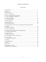
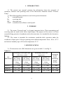
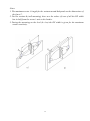
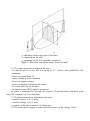
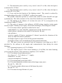
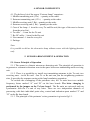
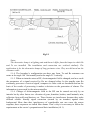
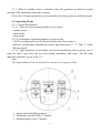
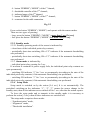
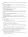
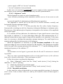
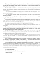
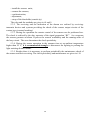
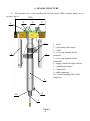
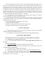
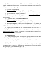
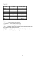
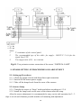
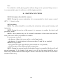
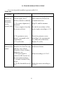
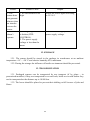
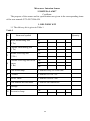
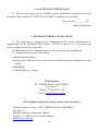
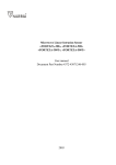
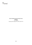
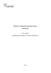
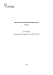
Microwave Intrusion Sensor “FORTEZA-LAMP” User manual 2010 TABLE OF CONTENTS User manual 1. Introduction ................................................................................................ 3 2. Purpose ........................................................................................................ 3 3. Specifications .............................................................................................. 4 4. Sensor Components .................................................................................... 8 5. Sensor Arrangement & Operation ............................................................. 9 5.1. Sensor Principle of Operation .................................................................. 9 5.2. Operation Modes ..................................................................................... 11 5.3. Sensor Operation ...................................................................................... 17 6. Sensor Structure .......................................................................................... 21 7. Safety Measures .......................................................................................... 24 8. Mounting Procedure .................................................................................... 25 8.1. Requirements for the sector’s preparation and the application conditions ...................................................................................................... 25 8.2. Sensor Mounting ...................................................................................... 26 8.3. Sensor Connection .................................................................................... 26 9. Sensor Setting-up Procedures and Adjustment ........................................... 32 9.1. Setting-up Procedures............................................................................... 32 9.2. Sensors Setup ........................................................................................... 32 10. Maintenance check ................................................................................... 33 10.1. Performance check of the sensors ......................................................... 33 10.2. Servicing ................................................................................................. 33 11. Troubleshooting guide............................................................................... 34 12. Storage ....................................................................................................... 35 13. Transportation ........................................................................................... 36 Certificate ........................................................................................................ 36 1 Delivery kit .................................................................................................. 36 2 Acceptance certificate ................................................................................. 37 3 Manufacturer’s guarantees ........................................................................... 38 2 1. INTRODUCTION 1.1 The present user manual contains the information about the principle of operation, structure and operating rules of the Microwave Intrusion Sensor “FortezaLamp”. 1.2 The following abbreviations are used in the present document: Tx - transmitting unit Rx - receiving unit DZ - detection zone CSCP - centralized surveillance control panel. 2. PURPOSE 2.1. The sensor “Forteza-Lamp” is a bistatic intrusion device. Their transmitting and receiving units are made in the form of park lamps. The purpose of the sensor is to form concealed long protective boundaries and at the same time it is intended for the decorative lighting. 2.2. The sensor is intended for continuous round-the-clock operation under the conditions of open space. It keeps operating at an ambient temperature from - 40 to +65 ˚С and relative humidity up to 98% at the temperature 35 ˚С. 3. SPECIFICATIONS 3.1. The detection zone (DZ) dimensions are given in table 3.1 and fig.3.1. Table 3.1 Mounting on the upper part of the fence (stile) Mounting on the wall (approach) Mounting on the level. Mounting height 0,85m Length (L) Distance of the sensor between the fence V=0,25m 3 … 30 m Distance of the sensor between the fence V=0,15m 3 … 20 m Distance of the sensor between the fence V=0,25m 3 … 20 m Distance of the sensor between the fence V=0,15m 3…12m Width (b) 0,5…2m 0,5…1,5m 0,5…1,5m 0,5…1m 0,5 …4m Height (h) 0,5…2m 0,5…1,5m 0,5…1,5m 0,5…1,2m 1,4…1,6m DZ dimensions 3 3…40m Notes. 1. The maximum sector’s length for the variants a and b depends on the dimensions of the fence V. 2. For the variant b (wall mounting) there are the values (b) not of all the DZ width but its half from the sector’s axis to the border. 3. During the mounting on the level (b=4 m) the DZ width is given for the maximum sensor sensitivity. 4 a –mounting on the upper part of the fence b –mounting on the wall c –mounting on the level (ground connection) Fig.3.1 – Detection zone of the sensor “Forteza-Lamp” 3.2. The sensor generates an alarm in the cases: - an intruder moves in the DZ at a speed of 0,1…6m/sec with probability 0,98 minimum; - there is no signal from Tx; - supply voltage is below standard; - there is no supply voltage; - there is an attempt to demount the sensor; - the sensor units are out of order; - the remote control (RC) signal is generated. An alarm is generated by opening the contacts of optoelectronic individual point relay (NC contacts) for 3 sec minimum. 3.3. The dimensions of the individual point relay: - switched current is 0,1 A max; - switched voltage is 50 V max; - resistance in the closed mode is 110 Ohm max. 3.4. The sensor power supply is realized from dc source of the voltage 24±8V. 5 3.5. The maximum power used by every sensor’s unit (Tx or Rx) when the light is switched ON is 12 Watt. 3.6. The maximum power used by every sensor’s unit (Tx or Rx) when the light is switched OFF is 0,6 Watt. 3.7. Every unit has the function of the lighting control. The control is realized by closing/breaking of the cable “CONTROL” on the power supply “-“. The parallel connection permits to control some units to switch ON/OFF the light synchronously. The cable resistance of the control line should not exceed 2kOhm. 3.8. The lighting at the distance of 1m from the unit is 47 lx (corresponds to the incandescent lamp of 75 Watt). 3.9. The sensor is immune to the influence of EMI (voltage impulses in the supply circuits, breaks of mains power supply, electrostatic discharges, electromagnetic fields). 3.10. The sensor doesn’t generate an alarm in the cases: - small animals (e.g. cats, birds like pigeons) move in the detection zone; - mobile phones operation in the radius ≥2 m from the Rx unit; - rain and snow; - wind at a speed of 10m/sec. maximum if it doesn’t provoke the vibrations of the fence on which the sensor is installed; - the height of grass is up to 0,3m (for the ground connection); - the height of snow is 0,6 m maximum (for the ground connection). 3.11. The input circuits are protected from the temporary overvoltage up to 900 V provoked by the pickups in the supply and communication lines during the storm discharge. 3.12. Operating frequency is 9375±70 MHz 3.13. The impulse power of the sensor beaming is 10 m/Watt, the mean beaming power (with the porosity of the microwave impulses) is 0,35 m/Watt. 3.14. The remote control characteristics: - dc voltage is 5…30 V relative to ”-“ supply; - duration is 1 sec min; - current consumption is 2 ma max. 3.15. The international protection is IP43. 3.16. The units dimensions without cases of the lamps (mm, max): - Rx and Tx – Ø90×190. 3.17. The units weight without cases of the lamps (kg, max): - Rx and Tx – 0,3; 3.18. The sensor average lifetime is 8 years. 6 4. SENSOR COMPONENTS 4.1. The delivery kit of the sensor “Forteza-Lamp” comprises: 1. Middle transmitting unit (2Tx) - quantity at the order. 2. Extreme transmitting unit (1 Tx) - quantity at the order. 3. Middle receiving unit (2 Rx) - quantity at the order. 4. Extreme receiving unit (1 Rx) - quantity at the order. 5. Case of the lamp - 1 item for every Tx and Rx unit (the type of the case is chosen from the price-list). 6. Tx cable - 1 item for the Tx unit 7. Rx-NC cable - 1 item for the Rx unit 8. User manual - 1 item for every kit. 9. Package. Note. It is possible to deliver the decorative lamp without sensor with the lighting function only. 5. SENSOR ARRANGEMENT & OPERATION 5.1. Sensor Principle of Operation 5.1.1 The sensor is a bistatic microwave detecting unit. The principle of operation is to generate a volumetric detection zone in the space between a transmitting and a receiving unit. 5.1.2. There is a possibility to install two transmitting antennas in the Tx unit; two receiving ones - in the Rx unit. One Tx or Rx unit can join the neighboring perimeter sites. It provides the expenses saving at the long boundaries generation. To exclude the overlapping of the perimeter sites, the Tx units have two variable frequency letters marked “A” and “B” on the base boards. The letter changing is performed by the jumper on the Tx base board. The Rx units are universal and can synchronize with the Tx unit of any letter. There are two independent channels of processing with their individual point relay, control and indication parts marked “I” and “II” on the Rx base board. 5.1.3. The principle of the perimeter’s sites generation is given in fig.5.1. 7 Fig.5.1 Notes. The decorative lamp is a lighting unit and doesn’t differ from the lamps in which Rx and Tx are installed. The installation and connection are realized similarly. The application is for the decorative lamps of long perimeter sites. They are delivered on the customer order. 5.1.4. The boundary’s configuration can have any form. Tx and Rx antennas can rotate at the angle 180˚ horizontally and at the angle 25˚ vertically. 5.1.5. When an intruder enters a DZ, electromagnetic field is changed; and as a result the parameters of a signal received by Rx are changed either. In the standby state Rx constantly processes a received signal, compares its value with set thresholds and on the basis of the results of processing it makes a decision on the generation of alarms. The information is processed by the microcontroller. 5.1.6. Change of electromagnetic field in the DZ can be caused not only by an intruder but by other factors too: vibration of grass, branches, bushes, small animals, rain, reflection from walls and barriers, etc. These factors are interference because they make difficult reliable friendly signal extraction (caused by an intruder) against their background. More than that, interferences of considerable rate can cause the sensor response; these responses are called false alarms. That’s why it is necessary to follow the requirements at the sector’s preparation and their installation (i.8.1). 8 5.1.7. When an intruder enters a detection zone, Rx generates an alarm by single opening of the individual point relay contacts. If the cause of alarm generation is not remedied, the sensor generates multiple alarms. 5.2. Operating Modes 5.2.1. General Information 5.2.1.1. There are three operating modes of the sensor: - standby mode; - alarm mode; - setup mode. 5.2.1.2. Indication of operating modes is carried out by: - CSCP according to the state of the individual point relay contacts; - different variants and combinations of three light indicators “1”, “2” and “3” on the Rx base board. 5.2.1.3. Light indicators are available only for the monitoring when a sensor case is removed; that’s why they can be used during installation and setup. The Rx light indicators position is given in fig. 5.2. Note. The signal channels II are absent in the extreme receiving unit (1Rx). 1 – supply board and lighting control; 2 – thresholds controller of the 1st channel; 3 – indicator lamps of the 1st channel; 9 4 – button “РЕЖИМ” (“MODE”) of the 1st channel; 5 – thresholds controller of the 2nd channel; 6 – indicator lamps of the 2nd channel; 7 – button “РЕЖИМ” (“MODE”) of the 2nd channel; 8 – connector for the cable connection. Fig. 5.2 Press on the button “РЕЖИМ” (“MODE”) and operate with the sensor modes. There are two types of pressing: - long: press the button “РЕЖИМ” (“MODE”) more than 3 sec [5-6 sec]; - fast: press the button “РЕЖИМ” (“MODE”) less than 3 sec [<3 sec]. 5.2.2. Standby mode 5.2.2.1.Standby operating mode of the sensor is indicated by: - closed state of the individual point relay contacts; - periodically short-time switching ON of “2” indicator if the automatic thresholding was performed; - periodically short-time switching ON of “3” indicator if the automatic thresholding was performed. 5.2.3. Alarm mode is indicated by: - individual point relay opening for 3 sec. If an alarm is continual or power supply fails, the individual point relay contacts are open permanently: - switching ON indicator “2” for 3 sec. or permanently (according to the state of the individual point relay contacts) if the automatic thresholding was performed; - switching ON indicator “3” for 3 sec. or permanently (according to the state of the individual point relay contacts) if the automatic thresholding was performed. 5.2.4. Setup Mode Setup mode is switched on by the action [5-6 sec]. It is set automatically. The periodical switching-on the indicators “1”, “2”, “3” means the sensor change in the standby state; then all the indicators are switched off for 3 sec; after that the action repeats. To leave the setup mode and to transmit in the standby mode it is necessary to perform the action [<3sec] when all three indicators are switched off. The setup mode comprises three modes: - “Synchronization” mode, - “Alignment” mode, - “Thresholds installation”. 10 ATTENTION! It is necessary to follow all the actions in order for the right setup. To pass in “Synchronization” mode, it is necessary to perform the action [<3sec] during the indicator’s glowing “1”. To pass in “Alignment” mode, it is necessary to perform the action [<3sec] during the indicators glowing “1” and “2”. To pass in “Thresholds installation” mode, it is necessary to perform the action [<3sec] during the indicators glowing “1”, “2” and “3”. To leave a mode, perform the action [5-6 sec]. 5.2.4.1. “Synchronization” mode Rx unit should correspond to Tx unit (letter “A” or “B”). That’s why the synchronization is necessary. The synchronization is performed when Tx and Rx antennas are adjusted. Follow the actions to perform the synchronization: a) Install the necessary frequency letter (“A” or “B”) according to the sectors generation principle (see i.5.1.3.). The jumper is installed – the letter “A”, the jumper is removed – the letter “B”. The jumper condition changing is performed by the disconnection and the next unit power-up. Note. It is recommended to disconnect the power supply by the white colored wire removing from the socket. b) Enter “Setup” mode (action [5-6 sec]); c) Enter “Synchronization” mode (action [<3 sec]) during the indicator’s glowing “1”; d) Check the synchronization with the indicators. The synchronization is performed successfully in the cases: - Two indicators “1” and “2” glow periodically for the sector generated Tx with the letter “A”; - All three indicators glow periodically for the sector generated Tx with the letter “B”. e) Leave “Synchronization” mode and enter “Setup” mode (action [5-6 sec]). If during synchronization Rx synchronizes with the features alien to “its own” Tx or it does not synchronize at all, it means that Tx of another sector prevents it or there is not beaming of “its own”. This situation is possible in the following cases: - detection zones axes of adjacent sectors form an acute angle; - adjacent sectors are different in length; - the synchronized Rx is situated in the place (e.g. the angles or pockets of obstacles) where there is a signal deformation; 11 - power supply is OFF on “its own” transmitter; - “its own” transmitter is not positioned. In this case it is necessary to switch off the power supply of other transmitters which can influence on the synchronization after that carry out this synchronization. 5.2.4.2. “Alignment” mode While alignment two tasks are solved simultaneously: - more accurate positioning of the transmitter and the receiver of one sector to each other; - a received signal level adjustment providing the sensor operation. The alignment is carried out by the turn of Tx and Rx antennas vertically and horizontally with the attachment fitting. Every indicator “1”, “2”, “3” in this procedure has five scales of glow frequency: from periodic switching-on with low frequency (infrequent blinking) to continuous glow. The increase of the indicator glow frequency corresponds to the increase of the amplitude of Rx input signal. If to consider all three indicators, the indication of input signal increase occurs from left to right, i.e. indicator “1” is a low-order digit of this ruler. The continuous glow of “3” indicator means that an input signal is large and the amplifier is in saturation. At the same time it is necessary to disalign the transmitter antenna turning up. Too small signal or no signal is indicated by the disconnection of all indicators. While the alignment it is necessary to get the maximum amplitude of Rx input signal providing the reserve from the saturation of Rx amplifier. The maximum acceptable level is a result of the constant glowing of the indicators “1”, “2” and the blinking with the maximum frequency of the indicator “3”. Notes. The maximum received signal is generated when the Rx and Tx antennas are situated in parallels. There are some separated maximums of the received signal because of the reflection from walls, obstacles and surface. These maximums are false. Follow the actions to perform the alignment: a) Enter “Alignment” mode from the “Setup” mode (action [<3sec]) during the indicators “1” and “2” glowing; b) Obtain the maximum level of the signal; c) Leave “Alignment” mode and enter “Setup” mode (action [5-6 sec]). 5.2.4.3. Thresholds installation In this mode the values of thresholds are set using controlled crossings of a detection zone’s sector. Later on these values are used by the controller when an alarm signal is generated. 12 This stage of the setup is very important because if it is carried out correctly, it provides the high immunity of the sensor to the influence of noise during operation and declared detection probability. The thresholds installation is carried out for each sector. Two people take part in training. One of them (an intruder) crosses a detection zone. The crossing of the detection zone comprises: - For the sensors installed on the upper part of the fence: the stile through the fence (you can use the stairs); - For the sensors installed on the wall: approach to the wall is right or intrusion through the window; - For the sensors installed horizontally: an intruder crosses a detection zone to “full height” and “bent” position. The crossing of the detection zone should be performed in the centre of the sector and at the distance of ¼ from the sector’s length from Tx and Rx. Choosing the “problem” places of a sector: in cavities, on heights and so on. An intruder is a person (his weight is 50-75 kg; height is 165-180 cm). The other person (an operator) checks the training process by indicators on the Rx base board. The training must be carried out preventing all noise (movement of outsiders or an operator near a detection zone or in it, traffic movement near the zone, etc.). It can cause the sensor training for noise but not for an intruder. For the thresholding turn the thresholds controller of the channel at the angle 45˚ towards “+” or “-“. After the performance of this action the thresholds will be installed in accordance with the position of the thresholds controller. The turn towards “-“reduces the threshold of action and increases the sensor sensitivity. The turn towards “+” increases the threshold of operation and reduces the sensors sensitivity. After the manual adjustment any actions to transmit the sensor in “Standby” mode is not necessary. The infrequent blinking of the indicator “3” is a result that the sensor is situated in “Standby” mode with the performed manual adjustment. It is recommended to begin the manual adjustment from the position “+”. During the crossings (see below) check an alarm of the sensor by the switching on the indicator “3” for the time 3 sec. If an alarm is absent, a higher sensitivity is installed with the turn of the controller at a small angle and then the check crossings are performed again. The period repeats until an alarm is generated. 5.3. Sensor Operation 5.3.1. Follow the actions for the sensors operation: - prepare a sector; 13 - install the sensors units; - connect the sensors; - synchronization; - adjustment; - setup of the thresholds (sensitivity). The rules and the methods are given in i.8 and 9. 5.3.2. The receiving and the indication of the alarms are realized by receivingtransmits devices and systems providing the check of the sensors output circuits of the contact type (contact breaking). 5.3.3. During the operation the remote control of the sensors can be performed too. The check is realized by the duty operator of the signal generation “RC”. As a response the sensors generate an alarm. It proves the sensors availability and the running order of the loop circuit. The user determines the check periodicity. 5.3.4. During the sensor operation in the summer time at an ambient temperature higher than 30˚ C, it is recommended strongly to disconnect the lighting to prolong the light-emitting diodes lifetime. 5.3.5. Besides there it is necessary to perform periodically the maintenance check of the sensors and their servicing. The check periodicity and maintenance are given in i.10. 14 6. SENSOR STRUCTURE 6.1. The external view of the medium Rx for the sensor (2Rx) without lamp case is given in fig.6.1. ∅90 9 6 3 2 7 5 4 1 8 10 3 Fig.6.1 15 1 – bean 2 – processing base board 3 – cable 4 – receiving antenna of the channel I 5 – receiving antenna of the channel II 6 –supply board and light control 7 – attachment fitting 8 – clamp bolt 9 –cable connector 10 – thread bushing M10 of the lamp case 6.2. The bearing structure of 2 Rx is bean 1 turned on the bushing of the lamp case 10 (the case is not shown) and is fastened with the bolt 8. The base board of processing 2 and the supply board 6 with the cable connector 9 are fixed on the bean. The cable 3 is passed through the bean, the case’s bushing and the lamp case and then through the connector 9 it is connected to the base board of processing. The receiving antennas 4 and 5 of the channels of processing “I” and “II” are installed on the bean and is connected to the base board of processing. The attachment fittings provide the possibility to turn the antennas at the angle 180˚ horizontally and at the angle 25˚ vertically. 6.3. The difference of 1Rx construction is the absence of the antennas “II” and the channel elements II on the base board of processing. 6.4. The difference of 1Tx and 2 Tx construction is the presence of the base board of the modulator (instead of the base board of processing) and the transmitting antennas (instead of the receiving ones). 6.5. The mounting and the installation of the sensors: a) Unpack the component parts; b) Install the lamp on the place with the self-cutting screws; c) Connect the cable of the unit 3 to the junction box. 7. SAFETY MEASURES 7.1. The staff must have the leave for work with electrical facilities up to 1000V voltage to install, set and maintain the sensor. 7.2. It is prohibited to mount and to maintain the sensor during lightning storm. 8. MOUNTING PROCEDURE 8.1. Requirements for the sector preparation and the application conditions 8.1.1. Installation on the upper part of the fence. 8.1.1.1. It is recommended to install the sensors on the upper part of the fence from the inside. Follow the requirements: a) The direct visibility should be provided between Tx and Rx; b) Height of the obstacles relative to the detection zone should not exceed 0,3m vertically and 0,1 m horizontally; c) No wind and other vibration of the obstacle; d) No bushes, branches of trees, sheet of water, water flow in the detection zone; e) The presence of decorative lanterns, video cameras, immovable small objects is possible. It is necessary to reduce the length of the sector at 10 % from the maximum one (see table 3.1) for every object; 16 f) If it is necessary to reduce the DZ dimensions to exclude the presence of people, animals, branches and bushes, choose the corresponding (minimum) sector’s length (see i.3.1). 8.1.2. Installation on the wall. 8.1.2.1. Follow the requirements: a) The direct visibility should be provided between Tx and Rx; b) No bushes, branches of trees, sheet of water, water flow in the detection zone; c) No wind and other vibration of the obstacle; d) The presence of decorative lanterns, video cameras, immovable small objects is possible. It is necessary to reduce the length of the sector at 10 % from the maximum one for every object. 8.1.3. Installation on the ground (ground connection). 8.1.3.1. Follow the requirements: a) The direct visibility should be provided between Tx and Rx; b) No bushes, branches of trees, high grass (>0,3 m), snow (>0,6 m); c) It is not recommended to install the DZ axis nearer than 1…1,5 m from the lengthy objects (fence, walls, etc.) because it can reduce the received signal level and the detection; d) The big object movement (car, gates, crowns of big trees, etc.) nearer than 3…5 m from the DZ axis is not recommended; e) The presence of decorative lanterns, trunks of the trees (without branches), and immovable small objects is possible. It is necessary to reduce the length of the sector at 10 % from the maximum one for every object. 8.2. Sensor Mounting 8.2.1. Mark the perimeter for the places where the units are mounted. Lay the main cables and signal lines. Follow the requirements 5.1.2, 5.1.3 and 8.1. 8.2.2. Install the sensors, supply units and commutation from the delivery kit and the junction boxes according to the project documentation and i.6 of the user manual. 8.3. Sensor Connection 8.3.1. Connect the necessary supply lines and alarm lines in the junction boxes (JB) according to table 8.1 and fig. 8.1. Before that pass the cables of the sensors units through the pressure seals of the junction boxes and cut off. The cables of the sensors are marked (see table 8.1). 17 Table 8.1 Color White Brown Green Yellow Grey Pink Tx cable Rx-NC cable + – – CONTROL RC + – – CONTROL NC I NC I Blue NC II Red NC II Notes. “+”, “– “– power supply of the sensors “СONTROL” – power supply of the LED “RC” – remote control signal (+5…30 V) “NC I” – normally closed relay contacts of the individual point relay for I channel of the signal processing; “NC II” – normally closed contacts of the individual point relay for II channel of the signal processing. 18 Notes. 1. T- terminator of the control panel 2. The recommended type of the cable: for supply - H05VV-F 2×1,0 for the signal lines UTP. 3. Two supply units (SU) – as a variant. Fig.8.1–Two perimeter sectors connection of the sensor “FORTEZA-LAMP” 9. SENSOR SETTING-UP PROCEDURES AND ADJUSTMENT 9.1. Setting-up Procedures 9.1.1. Check the supply circuits and alarm lines right connection. 9.1.2. Switch ON the sensor power supply. 9.1.3. Take off the lamps bowls from the cases of the sensors. 9.2. Sensors Setup 9.2.1. Transfer the sensor in “Setup” mode and adjust according to i.5.2.4. 9.2.2. Install the lamp bowls on the cases of the sensors after the setup. After the sensor adjustment it is recommended to carry out its trial operation for 2…3 days to reveal and eliminate possible mistakes of mounting and adjustment. 19 Note. To exclude the visible glowing of the indicator lamp (in the separated lamp cases), it is recommended to glue the indicators with the lightproof splice. 10. MAINTENANCE CHECK 10.1. Performance check of the sensors 10.1.1. During the sensor exploitation it is recommended to check remote control (RC) 1…3 times in a day. 10.2. Servicing 10.2.1. The sensor should be served by the technicians after special training and instruction. 10.2.2. During the service of the sensor it is necessary to conduct the check and preventive works. 10.2.2.1. Every month carry out the external examination of the sensor units and the state of the sector where Tx and Rx are installed. It is necessary to check: - the absence of dust, dirt, snow and ice on the lamp bowls; - the absence of outside objects in the sector where Tx and Rx are installed. 10.2.2.2. Every quarter: - carry out all the works specified as works carried out every month; - check the state of the cables and cable connections. 10.2.3. During the seasonal works the height of grass is controlled (for the wall and ground mounting). If the height of the grass is over 0,3m, the grass should be cut or removed by another method. If the height of snow is more than 0,6 m in the DZ, the snow should be taken away. 20 11. TROUBLESHOOTING GUIDE 11.1. List of possible troubles is given in table 10.1. Table 10.1 Possible Cause Trouble 1. The alarms are generated constantly on the control panel Repair 1. Communication signal or Check the cable integrity and its current supply line is right connection. Restore the broken (contacts oxidation). communication line. 2. The sensor alignment is disturbed. 3. Power supply is less than the norm or absent. Align Tx and Rx antennas. 4. The perimeter sector doesn’t correspond to the requirements. 5. Tx or Rx fails. Check the perimeter sector according to the requirements i.8.1 and remove the failure. Replace Tx or Rx. 2. False 1. There are moving alarms of the branches in a detection zone sensor and they cause alarms (branches of trees, bushes, high grass, etc). 2. The input signal is reduced on Rx because of the environment change. 3. Animals circulate in the sector. 4. The Rx thresholds are too low. Provide the accordance of the power supply according to i.3.4. Inspect the sector and remove interference factors. Adjust according to i.5.2.4.2. Adjust the sensor according to i.5.2.4.3. 21 Trouble 3. The sensor does not generate alarms when an intruder crosses the sector. 4. The LED doesn’t operate. Possible Cause Repair 1. Rx thresholds are too high. Adjust the sensor again according to i.5.2.4.3. 1. The lighting control line is broken (УПРCONTROL). 2. The power supply voltage is less than the norm. Check the line integrity and the power supply voltage. 12. STORAGE 12.1. The sensor should be stored in the package in warehouses at an ambient temperature +5С…+50 °С and relative humidity 85% maximum. 12.2. During the storage the influence of hostile environment should be prevented. 13. TRANSPORTATION 13.1. Packaged sensors can be transported by any transport (if by plane – in pressurized modules) if they are transported in covered cars, holds or covered bodies they can be transported at the distance up to 10 000 km. 13.2. The boxes should be placed to prevent their shifting or fall in case of jolts and blows. 22 Microwave Intrusion Sensor “FORTEZA-LAMP” Certificate The purpose of the sensor and its specifications are given in the corresponding items of the user manual 4372-43071246-058. 1. DELIVERY KIT 1.1 The delivery kit is given in Table 1. Table 1 № Name and symbol Quantity 1 Midle transmitting unit (2 Tx) № 2 Extreme transmitting unit (1 Tx) № 3 Middle receiving unit (2 Rx) № 4 Extreme receiving unit of the sensor (1 Rx) № № № № № № 5 Case of the lamp 1 item on every Tx or Rx unit 6 Tx cable 1 item on 2 Tx or 1 Tx 7 Rx-NC cable 1 item on 2 Rx or 1 Rx 8 User manual and certificate 1 item for the ordered kit 9 Package 10 Decorative lamp № № 23 2. ACCEPTANCE CERTIFICATE 2.1. The kit of the sensors given in Table 1 meets performance specifications of the Document Part Number 4372-43071246-058 and it is considered as operable. Date of issue _________20 . Quality department 3. MANUFACTURER’S GUARANTEES 3.1. The manufacturer guarantees the conformity of the sensor specifications to requirements of the Document Part Number 4372-43071246-058 if a user meets the service conditions and operating rules. 3.2. Warranty period is 18 months since the date of sale by the manufacturer. 3.3. Guarantees do not covert the sensors: - with mechanical failures; - and also those which are out of order because of natural disasters (lightning, fire and flood); - mishandling. 3.4. Mean lifetime is 8 years. Manufacturer JSC “OKHRANNAYA TECHNIKA” P.O. box 45 Tel/Fax: +7 8412 65-53-16 E-mail: [email protected] For warranty and post-warranty service you can contact: Technical Service Center of JSC “OKHRANNAYA TECHNIKA” P.O. box 45 442960 Zarechny, Penza region, Russia Tel/Fax: (+7) 8412 65 53 16 (multi channel) [email protected] 24