1
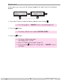
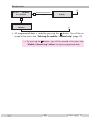
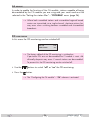
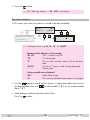
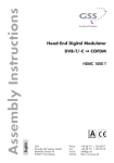
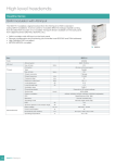
Head-End Station STC 160 Head-End Digital Modulator QAM HDMH 660 CI TPS English Notes on the Assembly Instructions. As well as this supplementary Assembly Instructions, the Assembly Instructions for the STC 160 apply. GSS Grundig SAT Systems GmbH Beuthener Strasse 43 D-90471 Nuremberg Phone: Fax: Email: Internet: +49 (0) 911 / 703 8877 +49 (0) 911 / 703 9210 [email protected] www.gss.de Contents 1 Safety regulations............................................................................................... 4 2 General information........................................................................................... 4 2.1 Scope of delivery................................................................................ 4 2.2 Meaning of the symbols used................................................................ 5 2.3 Technical data.................................................................................... 5 2.4 Description......................................................................................... 6 How the TPS module works................................................................... 7 Explanation of the term "symbol rate".................................................... 8 Bandwidth-efficient assignment of channels with low bandwidths.............. 9 3 Installation....................................................................................................... 10 3.1 Retrofitting a CA module.................................................................... 10 3.2 Installing the DVB-S2-QAM module...................................................... 11 3.3 Connecting the DVB-S2-QAM module.................................................. 12 4 The control panel at a glance............................................................................ 13 4.1 Menu items....................................................................................... 13 4.2 Functions of the control panel buttons................................................... 14 5 Programming................................................................................................... 15 5.1 Preparation...................................................................................... 15 5.2 Notes on level setting......................................................................... 15 5.3 Programming procedure..................................................................... 16 5.4 Programming the DVB-S2-QAM module............................................... 19 Selecting the module / channel strip.................................................... 19 Channel / frequency setting............................................................... 20 Output frequency.............................................................................. 21 Output channel................................................................................. 22 Switching the modulator of the channel strip off or on............................ 22 Output levels..................................................................................... 23 LNB oscillator frequency..................................................................... 23 Input symbol rate / DVB mode............................................................ 24 Setting the input symbol rate.......................................................... 24 Setting the DVB mode................................................................... 24 Input frequency................................................................................. 24 Station filter...................................................................................... 26 QAM modulation / User signal........................................................... 28 Setting the QAM modulation ...........................................................28 Inverting the user signal................................................................ 28 Data rate.......................................................................................... 29 Substitute signal in the case of an incorrect input signal ........................ 30 - 2 - HDMH 660 CI TPS Network Information Table (NIT).......................................................... 30 Network/operator identification.......................................................... 31 Deleting (data content) a PID / Renaming a PID.................................... 32 Deleting a PID (data content)......................................................... 32 Renaming a PID........................................................................... 33 Factory reset..................................................................................... 34 Saving data...................................................................................... 35 CA module....................................................................................... 36 PID monitoring............................................................................. 36 Configuring the CA module........................................................... 37 Selecting stations............................................................................... 38 6 Final procedures............................................................................................... 39 7 Channel and frequency tables........................................................................... 40 - 3 - HDMH 660 CI TPS 1S a f e t y regulations • The standards EN/DIN EN 50083 resp. IEC/EN/DIN EN 60728 must be observed. • Do not perform installation and service work during thunderstorms. • Assembly, installation and servicing should be carried out by authorised electricians. • Switch off the operating voltage of the system before beginning with assembly or service work. • Avoid short circuits! • Observe the relevant country-specific standards, regulations and guidelines on the installation and operation of antenna systems. • To ensure electromagnetic compatibility, make sure all connections are tight and the covers are screwed on securely. • No liability is accepted for damage caused by faulty connections or inappropriate handling of the device. Check the head-end station STC 160 according to the safety instructions listed in their assembly instruction. Take precautions to prevent static discharge when working on the device! Electronic devices should never be disposed of in the household rubbish. In accordance with directive 2002/96/EC of the European Parliament and the European Council from January 27, 2003 which addresses old electronic and electrical devices, such devices must be disposed of at a designated collection facility. At the end of its service life, please take your device to one of these public collection facilities for proper disposal. 2G e n e r a l 2.1S c o p e information o f d e l i v e ry 1 Head-end Digital Modulator QAM "HDMH 660 CI TPS" 1 HF connection cable 1 Brief Assembly Instructions - 4 - HDMH 660 CI TPS 2.2M e a n i n g —> – – • 2.3T e c h n i c a l o f t h e s ym b o l s u s e d / / Important note General note Optional use of the buttons Performing works data The requirements of the following EU directives are met: 2006/95/EC, 2004/108/EC The product fulfils the guidelines and standards for CE labelling (page 41). Unless otherwise noted all values are specified as "typical". HF input Frequency range:........................................................ 925 … 2150 MHz Level range:............................................................. 60 dBμV … 80 dBμV Input impedance:............................................................................. 75 Ω Return loss:......................................................................................8 dB DVB-S modes:............................................. DVB-S 1/2 , 2/3 , 3/4 , 5/6 , 7/8 DVB-S2 modes:....................QPSK 1/2 , 3/5 , 2/3 , 3/4 , 4/5 , 5/6 , 8/9 , 9/10 8PSK 3/5 , 2/3 , 3/4 , 5/6 , 8/9 , 9/10 Symbol rate DVB-S:........................................... QPSK: 2 … 45 MSymb/s Symbol rate DVB-S2:......................................... QPSK: 10 … 30 MSymb/s 8PSK: 10 … 31 MSymb/s LNB operating voltage:........................................... +12 V / 2 x ≤300 mA HF output Channels:............................................................................. S21 … C69 Frequency range:.............................................. 42.0 MHz … 860.0 MHz Types of modulation:...................................QAM 4, 16, 32, 64, 128, 256 Output level:.............................................................................. 83 dBμV Output impedance:.......................................................................... 75 Ω - 5 - HDMH 660 CI TPS Connections SAT inputs:.............................................................................. 2 F sockets HF output:................................................................................ 1 F socket Connection strip (20-pin):...................for supply voltages and control circuits Conditional access:............................several channels can be descrambled 2.4D e s c r i p t i o n The Head-End Digital Modulator HDTV "HDMH 660 CI TPS", in the following called DVB-S2-QAM module converts two DVB-S-/DVB-S2-modulated data streams into two QAM-modulated data streams. The DVB-S2-QAM module has two SAT-IF inputs and one HF output. Components (e.g. LNB) which are connected upstream can be powered through the SAT-IF inputs. The DVB-S2-QAM module is equipped with two channel strips ("A" and "B"). The channel strips consist of the digital SAT tuners, the digital signal processing levels and an output converter. The channel strips for the DVB-S2-QAM module are indicated in the head-end station display with "Bx …A" and "Bx …B". Using an adequate CA module scrambled channels can be descrambled via channel strip "A". The control of the module takes place via the control unit of the head-end station. Two LEDs indicate if the respective channel strip is switched on (LED illuminates) or off, and also provide an indication of the signal quality based on their colour. Additionally the quality of the data stream received is displayed ("CN…"). The integrated TP module (Transport Stream Processing) processes the data from the demodulated transport streams. This enables service information (NIT – Network Information Table) to be changed, data rates to be increased (stuffing) and for individual stations to be deleted from the transport stream (thus optimising bandwidth for the other stations being transmitted). In addition, the operator ID (required for e.g. visAvision) can be set. The HF output signals are sent through the HF output of the DVB-S2-QAM module to the output collector. When the head-end station is switched on, the two-line LC display shows the "SETUP" menu and the software version of the control unit. The head-end station output level can be adjusted in this menu. The DVB-S2-QAM module operating software can be updated using a PC or notebook and the software "BE-Flash" via the 9-pin SUB-D socket on the headend station. You can find the current operating software for the DVB-S2-QAM module, the software "BE-Flash" and the current assembly instructions on the website "www.gss.de". - 6 - HDMH 660 CI TPS The DVB-S2-QAM module is designed exclusively for use in the STC 160 headend station. H ow the TPS m o d u l e wo r ks After decoding QPSK- or 8PSK-modulated signals, the demodulated data stream can be accessed via the integrated TPS module. This data stream, also called transport stream, contains several stations in all their components (video, audio, data and service information), which can be changed using the TPS module. Station filter Individual stations can be deleted. This reduces the data rate and, consequently, the output symbol rate required. Stuffing The transport stream is padded using what is known as zero data. This ensures a steady and constant output symbol rate. Changing the NIT The transport stream contains data in the form of tables which the receivers evaluate and require for convenient use. The TPS module can adjust the "Network Information Table" (NIT) to accommodate the new station data. The "NIT" contains data which is required by the set-top box for the automatic search feature. Changing the operator ID (CAT) Some network operators transmit an operator ID in the data stream (e.g. visAvision). By changing the CAT the operator ID can be adjusted to the current demands. - 7 - HDMH 660 CI TPS E x p l a n at i o n of the term " s ym b o l r at e " Modulation schemes such as QPSK and QAM transmit multiple bits simultaneously. These are referred to as symbols. In addition to the user data flow which transmits video and audio information, error correction bits are transferred. The FEC number states the ratio of user bits to the complete transmitted bits. The output symbol rate is calculated as follows: 256-QAM:SR (A) = FEC x 1/4 x SR (E) 128-QAM:SR (A) = FEC x 2/7 x SR (E) 64-QAM:SR (A) = FEC x 1/3 x SR (E) 32-QAM:SR (A) = FEC x 2/5 x SR (E) 16-QAM:SR (A) = FEC x 1/2 x SR (E) 4-QAM:SR (A) = FEC x 1/1 x SR (E) Example: Output symbol rate 64-QAM, FEC= 3/4, Input symbol rate SR (E) = 27,500 kSymb/s SR (A) = 3/4 x 1/3 x 27,500 kSymb/s SR (A) = 6,875 kSymb/s —> If no "FEC" is stated in the station lists, it can be assumed to be "FEC = 3/4". Reception from a transponder with a very low symbol rate (SCPC station) The extremely low data rate means that the output symbol rate is very low. If there are reception problems with different digital receivers, set output symbol rate to a higher value. Defined symbol rates Some cable operators specify a fixed symbol rate (e.g. 6,900 kSymb/s). - 8 - HDMH 660 CI TPS B a n dw i dt h - e f f i c i e n t a s s i g n m e n t o f c h a n n e l s w i t h low ba n dw i dt h s (SelecPlex®) Channels with low bandwidths are the result of filtering out stations which are not required. These "narrow" channels can then be arranged in one channel to save space. To do this, activate the "Setting the output frequency" menu (assignment outside the official channel grid). —> The required bandwidth (in kHz) is roughly equal to the symbol rate (kSymb/s) plus 20%. S21 S22 ESC 1 Nile TV Nile News Viva Gala TVP 3 TV Polonia TVP 2 TVP 1 Cine 5 Fantasy Eutelsat 7° Ost S24 TVP 1 TVP 2 TVP 3 4 MHz 64 QAM 3,3 Ms/s Caution: The modulator in this module employs automatic neighbouring-channel assignment. This means that when the output channel or the output frequency for channel strip "A" is set, channel strip "B" will always be 8 MHz above channel strip "A". If SelecPlex® will be used, the normal channel separation of 8 MHz can be reduced to 2 MHz via the frequency setting for channel strip "B". Gala S23 3 MHz 64 QAM 2,5 Ms/s Viva Super Sport Türksat 42° Ost Nile News Nile TV Mediolanum TV Bulgaria SISAL TV RTP Eutelsat 13° Ost DW TV RAI UNO ESC 1 RTM 1 TV 5 Astra 19,2° Ost - 9 - HDMH 660 CI TPS 3I n s t a l l a t i o n – Ensure the head-end station is mounted so it will not be able to vibrate. Avoid, for example, mounting the head-end station onto a lift shaft or any other wall or floor construction that vibrates in a similar way. – Before installing or changing a module, switch off the head-end station or unplug the power cable from the mains power socket. Take measures to protect against ESD! • Open the housing of the head-end station in accordance with the assembly instructions for the STC 160. 3.1R e t r o f i t t i n g CA module The DVB-S2-QAM module is equipped with a common interface. It allows you to connect a CA module for various scrambling systems and service providers. Scrambled channels can only be descrambled with a CA module suitable for the scrambling system and the corresponding smart card. The smart card contains all the information for authorisation, descrambling and subscription. – Check with the distributor or manufacturer of the CA module to be used to ensure that it is suitable for the reception of several channels. – The hardware and software of the DVB-S2-QAM module have been thoroughly prepared and tested. – Any changes made by program providers to the structures in the program data might impair or even prevent this function. – When working with the CA module, please read the corresponding operating manual from the respective provider. • Insert the smart card 1 into the CA module 2 so that the chip 3 on the smart card faces the thicker side (top) of the CA module (fig. 1). • Push the CA module 2 without canting into the guide rails 4 of the common interface 5 according to the following picture and contact it to the common interface. a - 10 - HDMH 660 CI TPS 5 4 2 3 1 Fig. 1 3.2I n s ta l l i n g the DVB-S2-QAM module – Check that the plug contacts of the CA module are tightly seated in the terminal strips on the common interface of the DVB-S2-QAM module and make sure there is reliable contact. – When installing a module, make sure that it is inserted in one of the long, numbered grooves in front of the contact strip on the board at the rear wall of the housing. – The shorter, non-numbered grooves without a contact strip on the board at the rear wall of the housing are for add-on modules only. • Open the housing of the head-end station in accordance with the assembly instructions for the STC 160. • Open the locking device 1 in the direction of the arrow (fig. 2). 1 Fig. 2 • Insert the DVB-S2-QAM module in grooves A and B of an open slot (with contact strip on the board at the rear wall of the housing) and gently slide it into the head-end station until it makes contact with the board on the rear wall (fig. 3). • After installing the DVB-S2-QAM module close the locking device 1 in the direction of the arrow (fig. 3). - 11 - HDMH 660 CI TPS B A 1 Fig. 3 3.3 C o n n e c t i n g the DVB-S2-QAM module C D F G Fig. 4 • Connect SAT-IF inputs C on the DVB-S2-QAM module (fig. 4) to the preinstalled F terminals in the rear wall of the head-end station via the cable inlets F using HF cables made on-site (length approx. 80 cm) or if applicable connect each to one of the outputs of a retrofitted SAT-IF input distributor. • After programming, connect the modulator output D to one of the input sockets G of the output collector. - 12 - HDMH 660 CI TPS 4T h e control panel at a glance 4.1M e n u items Program the DVB-S2-QAM module using the buttons on the head-end station control panel. The menus appear on the two-line display of the control panel. The parameters and functions to be set are underlined. With the You can use the button select the channel strip / other modules. button to select the following menu items: – Activating the module and channel strip – Channel setting / frequency setting – Output channel / output frequency – Output level – LNB oscillator frequency – Input symbol rate – Input frequency – Station filter – CA module (if available, only channel strip A) PID Check Menu/Edit – QAM modulation – Stuffing – Substitute signal – Network Information Table (NIT) – Conditional Access Table (CAT) – Deleting/Renaming a PID – Factory reset – Save data - 13 - HDMH 660 CI TPS 4.2F u n c t i o n s o f t h e c o n t r o l pa n e l b u t to n s M S To To To To move the cursor, call up functions adjust values and functions save the programmed data switch to the next menu - 14 - HDMH 660 CI TPS 5P r o g r a m m i n g 5.1P r e pa r at i o n • Test the software versions of the head-end station and the DVB-S2-QAM module and update them if necessary. The current software versions can be found on the website "www.gss.de". • Connect the test receiver to the modulator output on the DVB-S2-QAM module D or to the HF output on the output collector if it is already connected (page 12). • Adjust the test receiver to the output channel / output frequency of the channel strip to be set. • Switch on the channel strip (modulator) if necessary (page 22). For each channel strip, there is an status LED which indicates if the channel strip is switched on. Status LED – Kanalzug ”A” Status LED – Kanalzug ”B” 5.2N ot e s In order to prevent interference within the head-end station and the cable system, the output level of the DVB-S2-QAM module must be lowered by 10 dB compared to analogue cassettes at 64 QAM, and by 4 dB compared to analogue cassettes at 256 QAM. Check the output level of the output collector according to the assembly instructions of the head-end station STC 160 and if necessary set it to the demand of the cable system. on level setting - 15 - HDMH 660 CI TPS 5.3P r o g r a m m i n g procedure Ein/On BE160 SETUP V 10 Bx 1A Bx 1A TWIN-SAT Böx 4 TWIN-SAT Bx 1B TPS C5-12,S3-24 C07 C5-12,S3-24 C07 858,0 MHz B V 15 TPS 850.0 MHz B V 15 A Page 18 M Bx 1A/B OUTPUT Freq. / Channel / Freq. / / M Bx 1A/B OUTPUT 850.0/858.0 on / / on / off M Bx 1A/B / LEVEL 0 dB 0 … -25 dB / / M Bx 1A/B LNB 10600 MHz M / / Bx 1A/B SYMBOL 27500 DVB-S DVB-S / DVB-S 2 M / / Bx 1A/B 11835 / / FREQ -1.1 CN 13 M Bx 1A/B PROGRAM Filter off M / M Bx 1A/B TV + Das Erste 01/09 / Programme entfernen / hinzufügen Removing / activating stations / nächster Service (Programm) next service (station) on / off Bx 1A CA PID Check on M S nur Kanalzug “A” mit CA-Modul only Channel strip “A“ with CA module / - 16 - HDMH 660 CI TPS / M / M next service (station) on / off Bx 1A CA PID Check on nur Kanalzug “A” mit CA-Modul only Channel strip “A“ with CA module / M Bx 1A CA Menu <= => Edit M Bx 1A TV X 04/09 .... M / X/0 X – entschlüsseln descrambling 0 – nicht entschlüsseln no descrambling / nächster Service next service Bx 1A 01/03 MENU S Information *) M *) Die angezeigte Information ist abhängig vom verwendeten CA-Modul. The information displayed is dependent on the CA module used. / / Bx 1A/B 4 … 256 QAM 256 normal / / normal / inverse M / / Bx 1A/B STUFFING SR=6900 (6531) M Bx 1A/B / FAILURE Single Carrier Null Packets / Single Carrier M Bx 1A/B / NIT off on / off / / neue NIT erstellen make new NIT => Make M Bx 1A/B CAT-ID 0xDE00 off / / on / off M / Bx 1A/B 01 PID –––– M / / - 17 - HDMH 660 CI TPS / 0xDE00 off / PID / / on / off M Bx 1A/B / 01 –––– M Bx 4 FACTORY Defaults => Werkeinstellung aufrufen invoke factory defaults M Bx 4 Bx 4 FACTORY STORE => M S A Page 16 M MEMORY S => STORE Einstellung speichern S store factory defaults A Page 16 STORE M CANCEL A - 18 - Page 16 HDMH 660 CI TPS 5.4P r o g r a m m i n g the DVB-S2-QAM module —> Pressing the button for longer than 2 seconds cancels the programming procedure. This takes you back to the program item "Selecting the module/channel strip" from any menu. Any entries that have not been saved are reset to the previous settings. —> Entries in the menus can be saved by pressing the key. You are taken back to the "Selecting the module/channel strip" menu item. • Switch on the head-end station. —> The display shows "SETUP BE160" and the software version of the head-end station (e.g. V 10). —> In the "SETUP" menu, the output level of the output collector can be adjusted (see STC 160 assembly instructions). Ein/On SETUP BE160 V 10 S e l e c t i n g the module / channel strip • If necessary, press repeatedly to select the particular module (Bx …) or channel strip "A" or "B" to be programmed. Bx 1A TPS 850.0 MHz A V 15 / - 19 - Bx 1A TWIN-SAT Böx 4 TWIN-SAT Bx 1B TPS C5-12,S3-24 C07 C5-12,S3-24 C07 858.0 MHz A V 15 HDMH 660 CI TPS —> The display shows, e.g., the "Bx 1A TPS" menu. "Bx" indicates the slot "1" indicates slot no. 1 "A" indicates channel strip "A" "TPS" Type of module "850.0 MHz" frequency set "V 15" software version of the module —> If a channel strip is selected whose modulator is switched off, instead of the frequency or the channel "– – –" is displayed. Bx 1B TPS OFF V 15 —> Programming the channel strips "A" and "B" is almost identical. Exceptions will be indicated. • Press the button. —> The "Channel / frequency setting" – "OUTPUT" menu is activated. Channel / In this menu, you can choose whether you require the channel or frequency setting for the adjustment of the HF output. The channel setting covers the range of channels S21 … S41 and C21 … C69, the frequency setting covers the range from 42.0 MHz to 860.0 MHz. frequency setting Bx 1A/B OUTPUT Bx 1A/B Freq. OUTPUT Channel The QAM signal is normally transmitted with a bandwidth of 8 MHz. This means that you can only use the channel centre frequency of the existing channel grid in the range of channels S21 … C69 (frequency grid 8 MHz). The CCIR channel grid is 7 MHz in the range of the lower frequency bands (channels C2 … S20). Therefore the frequency setting is used here. If one uses the existing channel grid of 7 MHz in these channel ranges, this will result in interference (overlapping) with the 8 MHz QAM signal packages, thus causing transmission problems. - 20 - HDMH 660 CI TPS For programming in these channel ranges and in the frequency ranges below them, we recommend starting with channel S21 / 306 MHz going back in steps of 8 MHz, or reducing the bandwidth of the QAM output signal by removing stations. The modulator in this module employs automatic neighbouring-channel assignment. This means that when the output channel or the output frequency for channel strip "A" is set, channel strip "B" will always be 8 MHz above channel strip "A". If SelecPlex® will be used, the normal channel separation of 8 MHz can be reduced to 2 MHz via the frequency setting for channel strip "B". Using "SelecPlex®" only the frequency setting can be used. • Use to select channel setting "Channel" or frequency setting "Freq.". • Press the button. —> The "Output channel" or "Output frequency" – "OUTPUT" menu is activated. —> If channel setting is selected continue with "Output channel". O u t p u t frequency In this menu you set the output frequency of the channel strip (42.0 … 860.0 MHz). Additionally the modulator of the channel strip can be switched off or on (page 22). The automatically assigned neighbouring frequency in channel strip “B” will be shown in the display next to the frequency to be set in channel strip “A”. If the output frequency of channel strip “A” is changed, the output frequency of channel strip “B” will follow with a frequency separation of 8 MHz (automatic neighbouring-channel assignment). Bx 1A/B OUTPUT 850.0/858.0 on • Use the buttons to position the cursor under the digit to be set for the frequency display then use to set the output frequency wished. —> Channel strip “B”: If SelecPlex® will be used, the normal channel separation of 8 MHz can be reduced to 2 MHz. - 21 - HDMH 660 CI TPS O u t p u t channel In this menu you set the output channel of the channel strip (S21 … S41, C21 … C69). Additionally the modulator of the channel strip can be switched off or on. The modulator in this module employs automatic neighbouring-channel assignment. This means that when the output channel for channel strip “A” is set, the output channel of channel strip “B” will always be one channel above channel strip “A”. The automatically assigned neighbouring channel in channel strip “B” will be shown in the display next to the channel to be set in channel strip “A”. If the output channel of channel strip “A” is changed, the output channel of channel strip “B” will follow with a channel separation of 8 MHz. • Use the S w i tc h i n g Bx 1A/B OUTPUT C67/C68 on buttons to set the output channel. t h e m o d u l ato r o f t h e c h a n n e l s t r i p o f f o r o n Bx 1A/B OUTPUT C67/C68 on • Using the button, move the cursor under "on" or "off" and then use the buttons to switch off "off" the channel strip (modulator) or to switch it on "on" if necessary. —> When it is switched off, the status LED for the channel strip goes out (see page 24). —> The switched off channel strip is indicated in the display with "– – –" instead of the channel or frequency display. Bx 1A - - - / C68 • Press the OUTPUT off button. —> The "Output levels" – "LEVEL" menu is activated. - 22 - HDMH 660 CI TPS O u t p u t levels This menu item is used to set the output levels of the modulators of the module´s channel strips to the same value and to level them to the output levels of the modulators of other modules used. In order to prevent interference within the head-end station and the cable system, the output level of the DVB-S2-QAM module must be lowered by 10 dB compared to the system level at 64 QAM, and by 4 dB compared to the system level at 256 QAM. Bx 1A LEVEL 0 dB • Use the test receiver to measure the output level of the channel strip and make note of the value. • When adjusting the second channel strip, compare its value with the value noted for the first channel strip. • Measure the output levels of the modulators of other modules used and make notes of their values. • Use the buttons to balance the higher output level of the one channel strip to the lower output level of the other channel strip and the output levels of the modulators of other modules used ("0 dB" … "–25 dB"). • Press the button. —> The "LNB oscillator frequency" – "LNB" menu is activated. LNB os c i l l ato r f r e q u e n c y Set the oscillator frequency of the LNB used in this menu. Bx 1A/B LNB 10600 MHz • Use the buttons to position the cursor under the digit of the frequency displayed. • Press to enter the respective digit of the oscillator frequency of the LNB used. • Repeat the procedure by the quantity of the digits to be set. - 23 - HDMH 660 CI TPS • Press the button. —> The "Input symbol rate" – "SYMBOL" menu is activated. I n p u t s ym b o l r at e / DVB mode The symbol rates of the satellite transponders can be found in the current channel table of the satellite operator, in various satellite magazines and in the Internet. The cassette recognizes the transmitted DVB mode and switches over between the normal QPSK mode (DVB-S) and the DVB-S2 mode. Receiving stations with DVB-S2 mode, we suggest to preset the DVB mode to shorten the time for searching stations. S e t t i n g Bx 1A/B SYMBOL 27500 DVB-S t h e i n p u t s ym b o l r at e • Use the buttons to position the cursor under the digit of the symbol rate displayed to be set. • Press to enter the respective digit of the desired symbol rate. • Repeat the procedure by the quantity of the digits to be set. S e t t i n g the DVB mode • Use the button to place the cursor under "DVB-S" and set the required DVB-S2-mode with the buttons . • Press the button. —> The "Input frequency" – "FREQ" menu is activated. I n p u t Once the HF receiver has synchronised to the input signal, any offset to the target frequency is displayed in MHz, e.g. "-1.8". The "CN…" indicator in this menu provides an indication of the signal-to-noise ratio of the received carrier. If the value is below "CN 5," this may result in loss of video. frequency - 24 - HDMH 660 CI TPS If a question mark "(?)" appears in the second line of the display, there is no input signal present. Check the configuration of the antenna system and headend station, as well as the previously adjusted module settings. Bx 1A/B 11835 FREQ -1.8 CN 12 • Use the buttons to position the cursor under the digit of the frequency displayed to be set. • Press to set the respective digit of the input frequency needed. • Repeat the procedure by the quantity of the digits to be set. • Set the frequency offset shown in the display (e.g. "– 1.8") to less than 1 MHz by varying the input frequency using the buttons. —> In addition to the indicator in the display, the quality of the transport stream received is indicated by a status LED: Status LED – Kanalzug ”A” Status LED – Kanalzug ”B” LED indicator Green Yellow Red Off • Press the Indication Signal quality is good Signal quality is poor No signal The channel strip (modulator) is switched off button. —> The "Station filter" – "PROGRAM" menu is activated. - 25 - HDMH 660 CI TPS S tat i o n f i lt e r The default setting for the station filter is "off". In this menu you define the stations received to be transmitted. If the station filter is switched off (factory default) all stations of the transport stream passes the station filter. As soon as the station filter is activated all stations are inactive and can be added to the transport stream selectively. If stations are activated the output data rate increases. Bx 1A/B PROGRAM Filter • Press the off S M Bx 1A/B TV + 01/09 Das Erste button. —> All stations from the channel strip will be read, and then displayed with name and station type. —> If no station is found, the following message will appear in the display "FILTER no Service". In this case, check the previously adjusted settings for the module as well as the components connected at the SAT input. —> The display shows e.g.:Bx 1A TV + 01/09 Das Erste Meaning of the indicators in the example: "Bx 1A" Slot 1, channel strip "A" "TV" TV channel type "+" The currently selected station is activated. "01/09" The 1st of 9 stations is being displayed. "Das Erste" Station name Further possible terms displayed: "RA" Radio channel type For radio stations, the background of the screen of the connected TV or test receiver is darkened. "–" The currently selected station is switched off. "HD" HD reception " * " The star means that the TV or radio station selected is scrambled. To enable the stations, the CA module and the appropriate smart card of the station provider are required. - 26 - HDMH 660 CI TPS —> If a service number (e.g. "131") appears instead of "TV" or "RA", this indicates that an unnamed station or an undefined data stream is being received. • Use the buttons to call up the stations in sequential order, then use to activate (indicated by " + ") or to deactivate them (" – "). —> Factory default: All stations are deactivated. • To save changes and to activate the station filter press the button. —> The display shows "PROGRAM Filter on". —> If stations are activated the corresponding PIDs (audio, video, text) are inserted into the data stream and the PAT and SDT tables are updated. —> The station filter remains deactivated ("off") if no station was activated. Test the status of the individual stations: If the station filter is switched on, press the button. In this mode you can use the buttons to scroll through the station list, and to deactivate activated stations or activate further stations. • In the "PROGRAM Filter on" menu the station filter can be switched "off" using the buttons . • Press the button. —> The "QAM modulation" – "QAM" menu is activated when the channel strips "A" without a CA module installed or "B" are programmed. —> Programming the channel strip "A" with a CA module installed the menus configuring the CA module – "CA" are activated (from page 36 on). - 27 - HDMH 660 CI TPS / User QAM In this menu, you can set the QAM modulation and invert the user signal. m o d u l at i o n signal Bx 1A/B 256 S e t t i n g the • Use QAM QAM normal m o d u l at i o n to set the QAM modulation ("4" … "256"). —> For higher QAM modulation, the output symbol rate is lowered. An output QAM modulation of > 64 QAM places a large burden on the cable network. Due to noise, delay and frequency response problems, reception of the converted output signal can be impeded. I n v e r t i n g the user signal For exceptional cases and "older" digital cable receivers, the spectral position of the user signal can be inverted. • Use • Use • Press the to place the cursor under "normal". to set the spectral position to "inverse". button. —> The "Data rate" – "STUFFING" menu is activated. - 28 - HDMH 660 CI TPS D ata r at e Bx 1A/B STUFFING SR=6900 (6531) Number 1 Number 2 SR=6900 (= "Number 1"): Active output symbol rate (6531) (= "Number 2"): The current measured output symbol rate. —> If the station filter is activated, this value is lower than the value of the "Number 1". The value fluctuates, since the data rates of individual stations are dynamically modified by the broadcasters. • Use the buttons to place the cursor under the number to be changed ("Number 1") and set the symbol rate with the buttons . The value set corresponds to the new output symbol rate. —> The "Number 1" can be increased to any value up to 7500. Caution: Symbol rates > 7000 kilosymbols/s increase the bandwidth of the output signal. Thus the output channels will overlap. In this case the bandwidth of the neighbouring-channels has to be decreased (see "SelecPlex®", page 9). Approximately calculation of the output bandwidth: Symbol rate [MSymb/s] x 1.15 = Bandwidth [MHz] 7.2 [MSymb/s] x 1.15 = 8.28 [MHz] 6.9 [MSymb/s] x 1.15 = 7.935 [MHz] —> With the station filter switched "on", the "Number 1" can be decreased. To do this, observe the "Number 2" for approx. 30 seconds and note the highest value. Add roughly 10 % to this value. Do not decrease the "Number 1" lower than the value of "Number 2". Is the "Number 1" lower than "Number 2" question marks "??" appear in the display. • Press the Bx 1A/B STUFFING SR=6200 (6531) ?? button. —> The "Substitute signal in the case of an incorrect input signal" – "FAILURE" menu is activated. - 29 - HDMH 660 CI TPS S u b s t i t u t e signal in the case of an incorrect input signal You use this menu to set whether a QAM signal filled with "Null Packets" or a "Single Carrier" signal should be provided as an output signal whenever an incorrect input signal occurs. Bx 1A/B FAILURE Null Packets • Use the • Press the buttons to set the output signal required. button. —> The "Network Information Table" – "NIT" menu is activated. N e t wo r k I n f o r m at i o n Ta b l e (NIT) Bx 1A/B off NIT => Make • To switch the NIT on or off ("on"/"off") press the • Press the buttons. button to activate the NIT ("Make"). All active cassettes which are able to output a NIT ("NIT cassettes") must be set and ready for reception. —> The NIT of all "NIT cassettes" are switched on. —> The cassette fetches all the information (output frequencies, output data rates, etc.) it needs from all the "NIT cassettes" in order to generate the NIT. This process may take a few seconds. Then the NIT is generated, added and sent to all "NIT cassettes". The other "NIT cassettes" also add this new NIT. The status of all "NIT cassettes" in the NIT menu changes to "on". The display shows: "read … / copy …". • To switch off the new NIT ("off") press the - 30 - button. HDMH 660 CI TPS —> The NITs of the other "NIT cassettes" will stay switched on. When the NIT of the cassette is switched on again ("on") by pressing the button, the previously generated NIT is added again. If you have changed parameters in the meantime, you must first select "Make" to generate a new, up-to-date NIT. —> Using the PSW 160 remote control software a NIT for several stations can be created. • Press the button. —> The "Network/operator identification" – "CAT-ID" menu is activated. N e t wo r k /o p e r ato r i d e n t i f i c at i o n In this menu, you can change the network/operator identification (CAT-ID – Conditional Access Table - Identification), for example of the visAvision transponder (Eutelsat 8° West). Bx 1A/B CAT-ID 0xDE00 off CAT is not to be changed: • Press the button. —> The "Deleting/Renaming a PID" – "PID" menu is activated (page 32). CAT is to be changed: The network operator e.g. requires that you set the operator ID of the visAvision transponder to "2". • Use the buttons to position the cursor under the digit of the operator ID to be set. • Use to change the operator ID from "0xDE00" to "0xDE02". • Use the button to position the cursor under "off," then use to activate the new CAT "on". —> The menu display switches to "modified". —> If you try to change the network/operator identification (operator ID) of a transponder which cannot be modified, "not modified" appears in the display. - 31 - HDMH 660 CI TPS • Press the button. —> The "Deleting/Renaming a PID" – "PID" menu is activated D e l e t i n g ( data co n t e n t) a PID / R e n a m i n g a PID In this menu you can delete or rename up to 9 PIDs of the transport stream. The changes are stored at 9 memory locations. Bx 1A/B 01 PID –––– —> First, memory location 01 is shown. Bx 1A/B 01 D e l e t i n g a PID ( data PID –––– co n t e n t) In this menu the data content of a PID of the transport stream can be deleted (tables will not be changed). • First, select the desired memory location using buttons . • Use button to place the cursor under the right digit of the PID input field ("– – – –") and set the hexadecimal number of the PID to be deleted (e.g. 1FFE) using buttons . Bx 1A/B 01 x1 FFE PID drop —> "drop" is displayed at the right side. • Repeat this process in order to delete more PIDs (max. 9). —> In order to undo any changes, select the corresponding memory location(s) and set the hexadecimal number of the PID, which was dropped, to "1FFF" —> "– – – –" is displayed. - 32 - HDMH 660 CI TPS R e n a m i n g a PID In this menu you can allocate a new address to a PID retaining the complete data content. • First, select the desired memory location using buttons . • Use button to place the cursor under the right digit of the PID input field ("– – – –") and set the hexadecimal number of the PID to be changed (e.g. 1FFE) using buttons . Bx 1A/B 01 x1 FFE PID drop • Place the Cursor below the "drop" indicator using button • Enter the new PID (e.g. 1FFD) using buttons . Bx 1A/B 01 x1FFE . PID –>x1FFD • Repeat this process in order to rename more PIDs (max. 9). —> In order to undo any changes, select the corresponding memory location(s) and set the hexadecimal number of the PID, which was renamed, to "1FFF" —> "– – – –" is displayed. • Press the button. —> The "Factory reset" – "FACTORY Defaults" main menu is activated. - 33 - HDMH 660 CI TPS Fac to ry reset In this menu you can reset all settings (together for both lines) to the factory defaults. Bx 1A/B FACTORY Defaults Bx 1A/B => M FACTORY STORE => S S M • If you don´t like to invoke the factory defaults press button . —> The "Saving data" – "MEMORY" menu is activated (Page 35). • Press the button. —> The factory defaults are invoked ("FACTORY STORE"). • Press the button. —> The factory defaults are saved. The display shows "STORE" —> Return to "Selecting the module" (page 19). —> By pressing the button the "Saving data" – "MEMORY" menu is activated. - 34 - HDMH 660 CI TPS S av i n g data Bx 1A/B MEMORY S => STORE A S Einstellung speichern store factory defaults STORE M CANCEL A • All programmed data is saved by pressing the button. You will be returned to the menu item "Selecting the module / channel strip" (page 19). —> By pressing the button, you will be returned to the menu item "Module / channel strip" without saving the programmed data. - 35 - HDMH 660 CI TPS CA In order to enable the function of the CA module, stations capable of being descrambled by the CA module you are using and your smart card must be selected in the "Setting the station filter" – "PROGRAM" menu (page 26). module —> Where both scrambled stations and unscrambled regional broadcasters are transmitted via a single channel, short-term picture loss may occur when switching between scrambled and unscrambled broadcasts. PID m o n i to r i n g In this menu the PID monitoring can be switched off. Bx 1A CA PID Check on —> The factory default of the PID monitoring is switched on. If particular PIDs are not descrambled the CI module is reset. Additionally dropouts may occur if several stations are descrambled. To prevent this the PID monitoring can be switched off. • Use the • Press the buttons to switch "off" or "on" the PID monitoring. button. —> The "Configuring the CA module" – "CA" submenu is activated. - 36 - HDMH 660 CI TPS Configuring The menu varies according to which CA module you are using. For this reason, please refer to the operating manual of your particular CA module. The relevant information is shown in the head-end station. This may appear as a fixed display or as scrolling text according to display capabilities. the CA module Bx 1A S M Bx 1A 01/03 MENU Information *) CA Menu <= => Edit M C M Bx 1A S TV X 04/07 .... —> By pressing the button you can skip the "Configuring the CA module" – "CA" menu and activate the "QAM modulation" – "QAM" menu (page 28). • Press the button to activate the menu of the CA module. —> The display shows e.g.: Bx 1A 01/03 MENU Information Meaning of the indicators: "Bx 1A" Slot 1, channel strip "A" "01/03" The first of three menu items is activated. "MENU" The menu of the CA module is activated. For the explanation of further details please use the operating instructions of the CA module used. • Use the buttons to activate the menu desired. • Press the button to activate the menu. • Use the buttons to select the function desired. • To set the CA module use the and buttons. • All settings are saved by pressing the button. —> You will be returned to the "Configuring the CA module" – "CA" menu item. —> By pressing the button you can cancel the settings in the menu of the CA module and are returned to the "Configuring the CA module" – "CA" menu. - 37 - HDMH 660 CI TPS • Press the button. —> The "Selecting stations" – "CA Edit" is activated. S e l e c t i n g s tat i o n s In this menu you select the stations wished to be descrambled. Bx 1A S M Bx 1A 01/03 MENU Information *) CA Menu <= => Edit M C M Bx 1A S TV X 04/07 .... —> The display shows e.g.:Bx 1A TV X 04/07 .... Meaning of the indicators in the example: "Bx 1A" Slot 1, channel strip "A" "TV" TV channel type "X" The currently selected station will be descrambled. "04/07" The 4th of 7 stations read is being displayed. ". . . ." Station name Further possible terms displayed: "RA" Radio channel type "0" The currently selected station remains unchanged. • Use the buttons to call up the stations in sequential order which are to be descrambled, then use to descramble (" X ") or not to descramble them (" 0 "). • Save changes and activate the station filter: Press the button. - 38 - HDMH 660 CI TPS —> The filter is activated. The display shows the "Configuring the CA module" – "CA" menu. Bx 1A Menu <= • Press the CA => Edit button. —> The "QAM modulation" – "QAM" menu is activated (page 28). 6F i n a l pro c e d u r es After installing the head-end station, upgrading accessories or installing modules it is necessary to tighten all cable connections, cable terminals and cover screws in order to maintain compliance with current EMC regulations. • Securely tighten the cable connections using an appropriate open-ended spanner. • After programming, connect the modulator output D to one of the input sockets G of the output collector (page 12, fig. 4). • Test the output level of the output collector according to the STC 160 assembly instructions and set the output level required for the cable system. • Mount the base plate and the front cover (see STC 160 assembly instructions). - 39 - HDMH 660 CI TPS 7 Channel Advice for a frequency grid (8 MHz) in the band I/III Frequenz Frequency [MHz] Frequenz Frequency [MHz] Frequenz Frequency [MHz] Frequenz Frequency [MHz] Frequenz Frequency [MHz] Frequenz Frequency [MHz] 42.00 50.00 58.00 66.00 74.00 82.00 114.00 122.00 130.00 138.00 146.00 154.00 162.00 170.00 178.00 186.00 194.00 202.00 210.00 218.00 226.00 234.00 242.00 250.00 258.00 266.00 274.00 282.00 290.00 298.00 346.00 354.00 362.00 370.00 30 31 32 33 378.00 386.00 394.00 402.00 S S S S 34 35 36 37 410.00 418.00 426.00 434.00 S 38 S 39 S 40 S 41 442.00 450.00 458.00 466.00 C C C C C C C C C C 51 52 53 54 55 56 57 58 59 60 714.00 722.00 730.00 738.00 746.00 754.00 762.00 770.00 778.00 786.00 C C C C C C C C C 794.00 802.00 810.00 818.00 826.00 834.00 842.00 850.00 858.00 Kanal Channel Kanalmittenfrequenz Channel centre frequency [MHz] Kanal Channel S S S S Kanalmittenfrequenz Channel centre frequency [MHz] 26 27 28 29 Kanalmittenfrequenz Channel centre frequency [MHz] Kanal Channel S S S S CCIR – Band IV/V (frequency grid 8 MHz) C C C C C C C C C C 306.00 314.00 322.00 330.00 338.00 Kanal Channel 21 22 23 24 25 Kanalmittenfrequenz Channel centre frequency [MHz] S S S S S Kanalmittenfrequenz Channel centre frequency [MHz] CCIR – Hyperband (frequency grid 8 MHz) Kanal Channel and frequency tables 21 22 23 24 25 26 27 28 29 30 474.00 482.00 490.00 498.00 506.00 514.00 522.00 530.00 538.00 546.00 C C C C C C C C C C 31 32 33 34 35 36 37 38 39 40 554.00 562.00 570.00 578.00 586.00 594.00 602.00 610.00 618.00 626.00 C C C C C C C C C C 41 42 43 44 45 46 47 48 49 50 634.00 642.00 650.00 658.00 666.00 674.00 682.00 690.00 698.00 706.00 - 40 - 61 62 63 64 65 66 67 68 69 HDMH 660 CI TPS CE - Declaration of Conformity Alterations reserved. Technical data E. & O.E. © by GSS GmbH V15/19062012