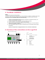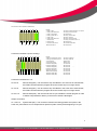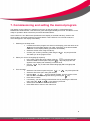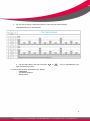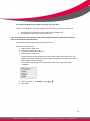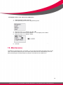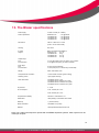
1
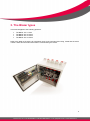
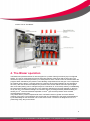
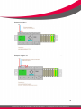
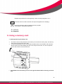
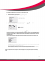
The Blazer
Aspiration maintenance unit
User manual
Contents
1. Disclaimer
Page 3
2. Introduction
Page 3
3. The Blazer types
Page 4
4. The Blazer operation
page 5
5. The Blazer installation
page 6
6. Overview of the connections on the Logo! PLC
Page 6
7. Commissioning and setting the desired program
Page 8
8. Programming the LOGO ! PLC
Page 11
9. Using a memory card
Page 12
10. Maintenance
Page 15
11. Causes of faults
Page 16
12. Precautionary measures
Page 16
13. The Blazer specifications
Page 17
14. System setup example
Page 18
2
FIRESENSE
Stammerkamp 19 • 1112 VE DIEMEN • THE NETHERLANDS • T +31 (020) 669 41 90 • I www.firesense.nl
1. Disclaimer
1. All the information in this manual has been written with the greatest possible care. However it
may contain inadvertent errors or omissions. FireSense denies all liability for any omissions or
errors.
2. In cases where we cannot verify the user's knowledge of this manual, FireSense cannot be
held liable in the event of an accident, loss or damage caused by inadequate understanding of
this manual. FireSense cannot be held liable for possible loss or damage caused by the use of
this product or in respect of any claims made by third parties (contractor, supplier, etc…).
3. FireSense is only responsible for problems that are inherent to the device, excluding any loss
of data from the LOGO! PLC and/or any other indirect losses resulting from a fault in the
software, maintenance work or other accidents.
4. Copying, publishing or storing this manual in a publicly accessible system and/or translating it
into a different language is strictly forbidden unless prior written permission has been obtained
from FireSense BV in the Netherlands.
2. Introduction
The Blazer has been developed in order to carry out periodical maintenance to the pipe network in an
aspiration system. The product has been designed and build to ensure very simple installation and
commissioning.
The Blazer is equipped with multiple inputs and outputs. For example, in order to ensure that The
Blazer operates at the exact air pressure, to generate a fault message and in order to shut down the
unit in an emergency. These features ensure that the device continues to operate correctly, resulting
in a correct constant flow rate in the suction pipe network in the aspiration detection system, based on
regular maintenance of the suction holes.
This system is part of a fire detection system and must be connected to a power supply that complies
with the local requirements. These requirements may vary by country.
3
FIRESENSE
Stammerkamp 19 • 1112 VE DIEMEN • THE NETHERLANDS • T +31 (020) 669 41 90 • I www.firesense.nl
3. The Blazer types
This manual applies to the following products:
•
•
•
•
The Blazer 100
The Blazer 200
The Blazer 300
The Blazer 400
1 valve
2 valves
3 valves
4 valves
Refer to the label on the device for information such as the nominal power rating, model and the serial
number. Write this information down before commissioning the device.
4
FIRESENSE
Stammerkamp 19 • 1112 VE DIEMEN • THE NETHERLANDS • T +31 (020) 669 41 90 • I www.firesense.nl
Interior view of The Blazer:
4. The Blazer operation
The Blazer will operate and blow air into the pipes for a period of time governed by a pre-configured
setting. The use of compressed air ensures thorough cleaning of the pipes and suction holes. The
valves are kept at a constant pressure by an extra pressure valve. The first valve is activated when the
program starts, followed by the pressure valve blowing compressed air into the pipe. The compressed
air is blown into the pipe in 1-second pulses for a period of 20 seconds (settings can be changed by
the user). After the set time has elapsed, the pressure valve closes and the first valve opens again
after 2 seconds (setting can be changed subject to a maximum of 10 seconds), thereby re-establishing
the normal flow condition in the first pipe. The maximum cleaning time per pipe depends on the time
set by the user. The standard setting is 40 seconds. After a preconfigured time (standard setting is 1
nd
nd
minute), the 2 valve will deactivate aspiration in the 2 pipe and the pressure valve will blow
compressed air into the pipe.
The pulsed delivery of the compressed air from The Blazer results in gentler and more effective
cleaning of the pipes. The pulsations also ensure that any dirt attached to the pipes will be displaced
by the alternating air flow and blown out via the suction holes. The device is designed for use in a
(extremely) dusty, dirty environment.
5
FIRESENSE
Stammerkamp 19 • 1112 VE DIEMEN • THE NETHERLANDS • T +31 (020) 669 41 90 • I www.firesense.nl
5. The Blazer installation
NOTE:
The Blazer may only be mounted vertically.
The Blazer is delivered with pre-fitted pipes of 27 mm in diameter; an adapter is available if pipes of 25
mm are to be used. The red/gray fittings inside The Blazer may not be glued in place under any
circumstances. Use of adhesive at this point voids the warranty.
1. Take the 4 mounting brackets and screw them to the back of The Blazer's housing. You
need to remove the plastic cover first.
2. Position The Blazer on the wall before marking and drilling the holes.
3. Attach The Blazer to the brackets using the screws supplied.
4. Now you can connect the pipes and make the various connections to or from the detector
and/or the fire detection control unit.
5. The compressed air supply may now be connected to the 12 mm female connector under
the housing.
NOTE: the compressed air supply must be free of oil and other contaminants.
6. Overview of the connections on the Logo! PLC
LOGO ! PLC and extension module:
1 2
4 5 6 7 8 9
3
2
11
12
13
14
15
16
17
10
10
Legend
1
24V (+)PLC
24V (-)PLC
3
Input for the choice of program
4
24V (+)PLC
5
24V (-) PLC extension
6
Pressure sensor
7
Remote Stop (NO)
8
Remote Stop (NC)
9
Remote Start (NO)
No function
11
No function
12
Valve 1
13
Valve 2
14
Valve 3
15
Valve 4
16
Air valve 5
17
System fault (NC)
6
FIRESENSE
Stammerkamp 19 • 1112 VE DIEMEN • THE NETHERLANDS • T +31 (020) 669 41 90 • I www.firesense.nl
Connection terminal 1 (Next to LOGO! PLC):
1 2 3 4
11
12
13
14
5 6 7 8 9 10
15
16
17
18
19
20
Legend
1 24V (+) PLC
2 24V (+) PLC extension
3 24V (+) I1 / I8 PLC
4 24V (-) Valve 2 & 3
5 24V (-) PLC
6 24V (-) PLC extension
7 No function
8 No function
9 Ground valve 2 & 5
10 Ground valve 1
11
12
13
14
15
16
17
18
19
20
Legend
1 24V (+) Connection term.1
2 24V (-) Connection term. 1
3 Ground door
4 Ground housing
5 Remote stop (No)
6 Remote Stop (No)
7 Remote stop (NC)
8 Remote stop (NC)
9 Remote start (No)
10 Remote start (No)
11 System fault (NC)
12 System fault (NC)
13 24V (+) External
14 24V (-) External
15 Not used
16 Not used
17 Not used
18 Not used
19 Not used
20 Not used
21 Not used
22 Not used
23 Not used
24 Not used
24V (+) Connection term. 2, Q3 ext.
24V (+) Pressure valve
No function
24V (-) Valve 1 & 4
24V (-) Valve 5
24V (-) Pressure valve
24V (-) Connection term. 2
No function
Ground valve 3 & 4
No function
Connection terminal 2 (In the housing):
1
2 3 4 5 6 7 8
9 10 11 12
13 14 15 16 17 18 19 20 21 22 23 24
Connection terminals 5 to 12:
X1.5/x1.6
Remote stop (NO) - Can be used to stop The Blazer in the event of an external fault;
the ETBU continues with the program when the remote stop is no longer active.
X1.7/x1.8
Remote stop (NC) - Can be used to stop The Blazer in the event of an external fault;
the ETBU continues with the program when the remote stop is no longer active.
X1.9/x1.10
Remote start (NO) - Can be used to start a cycle outside the normal program in order
to initiate compressed air delivery in the event of extreme blockages.
Output connection:
X1.11/X1.12
System fault (NC) - The contact is closed in the resting position and opens in the
event of a power failure or low compressed air pressure (under 4 bars) at the beginning of a cycle.
7
FIRESENSE
Stammerkamp 19 • 1112 VE DIEMEN • THE NETHERLANDS • T +31 (020) 669 41 90 • I www.firesense.nl
7. Commissioning and setting the desired program
The display on the LOGO! PLC switches on as soon as the 24V supply is connected and the
RUN/STOP LED illuminates. This LED turns green after approximately 5 seconds. The Blazer is now
ready for operation. Now execute the procedure described below.
If the LOGO! PLC is in RUN mode (FireSense in the display or the date and time), switch to the
STOP mode in accordance with the procedure below. If the LOGO! PLC is in STOP mode, the
menu will appear in the display immediately.
1. Switching to the Stop mode
• If FireSense and the program are shown in the display, press the down arrow
the time and date appear now. Next, press ESC. If the time and date
are shown on the display initially, press ESC immediately.
• Select the STOP menu using the OK key.
• Confirm your choice by selecting YES using the
key and press OK.
This takes you to the program menu.
2. Select your choice of language (if required)
• In the menu, select the set-up option using the
key and press OK.
• Select the MENU LANG option using the
key and press OK. EN
appears in the display with a flashing cursor on the E.
• Use the
key to select the desired language (EN for English) and
press OK.
3. Time and date
• Select the Clock menu option using the
or
keys and press OK.
• Select the Set Clock menu using the OK key.
• Use the
or
keys to change the date. As soon as the correct
date has been entered, change the time by pressing the
key.
• Press OK to confirm.
• If necessary, you can set the summer/winter time by selecting the S/W time
menu using the
or
keys and then press OK.
• Select ON to activate the summer/wintertime
• Press ESC twice to return to the main menu
8
FIRESENSE
Stammerkamp 19 • 1112 VE DIEMEN • THE NETHERLANDS • T +31 (020) 669 41 90 • I www.firesense.nl
4. You can now choose the desired program by connecting the desired input(s)
(see table below) to a +24V terminal.
5. You can select Start in the menu using the
have connected a program.
or
keys, or automatically if you
You will see the following information in the display:
- FIRESENSE
- The desired program
- Date and time
9
FIRESENSE
Stammerkamp 19 • 1112 VE DIEMEN • THE NETHERLANDS • T +31 (020) 669 41 90 • I www.firesense.nl
Example Program 2
Example. Program 10
10
FIRESENSE
Stammerkamp 19 • 1112 VE DIEMEN • THE NETHERLANDS • T +31 (020) 669 41 90 • I www.firesense.nl
8. Programming the LOGO! PLC
Changing parameters The following parameters can be changed:Program 1:
The compressed air delivery time per pipe is set to 25 seconds as standard and can be
set to a value between 10 and 60 seconds.(Note! The time must be set to at least 10
seconds.)
Program 2:
The pulse time for the compressed air delivery valve is set as standard to 50/25
milliseconds. This can be set to any value by the user.
Program 3:
The slow pulse time for the compressed air delivery valve is set as standard to 2/1
seconds. (PLC +24V input 8). Freely configurable.
Program 4:
The delay after compressed air delivery stops and the valve reopens. This is the time
required to allow the air in the pipe and valve to escape. This delay may be set to a
maximum of 10 seconds. A time of 2 seconds is the default minimum value (even if you
set 0 seconds) in order to protect the detector.
Setting these parameters:
Press the down arrow (date and time on the display)
ESC
Press the ESC key (the menu appears)
Press the down arrow once (Parameters menu)
OK
Press OK( Prog. 1 appears in the display)
OK
Press OK once in order to change the parameters.
Use the arrows to change the values.
OK
Press OK to confirm the changes.
11
FIRESENSE
Stammerkamp 19 • 1112 VE DIEMEN • THE NETHERLANDS • T +31 (020) 669 41 90 • I www.firesense.nl
Repeat the procedure from the beginning in order to change programs 2 to 4.
ESC
Press ESC twice in order to exit the menu (the time appears in the display).
Press the up arrow in order to display the menu program.
Test program 7 indicates programme 1.
TH = pulse time
TL = pause time
Ta = actual time.
9. Using a memory card
1. Inserting/removing a memory card
•
•
•
You have to remove the protective cover before you can insert a memory card. The memory
card can be removed in the same way.
To remove the protective cover, insert a flat screwdriver with a 3 mm blade in the recess at
the top of the cover and carefully lever the cover away from the slot. You can now pull the
cover or the memory card out of the slot.
NOTE: Make sure the memory card is in the right orientation before inserting it into the
slot.
12
FIRESENSE
Stammerkamp 19 • 1112 VE DIEMEN • THE NETHERLANDS • T +31 (020) 669 41 90 • I www.firesense.nl
2. Transferring data from the Logo! PLC to the memory card.
1. Insert the memory card in the slot.
2. Use the “ESC/Stop” key to open the programming menu.
3. Select the “card” option in the main menu using the
4. Press OK. This takes you to the transfer menu.
keys.
5. Move the cursor ‘>’ to “LOGO! -> card” using the
keys.
6. Press OK.
LOGO! now proceeds to copy the program data to the memory card (if a non-compatible memory
card for the versions 0BA0 .. 0BA4 has been inserted, the following message appears “unknown
card/press ESC”).
The main menu will appear again when LOGO! has finished copying data to the memory card.
The programme has now been copied to the memory card. You can now remove the memory
card. Do not forget to refit the protective cover.
If a power failure takes place during the transfer operation, the procedure must be repeated
from the beginning. Obviously, as soon as the power supply has been restored.
Note: The password in the Logo! PLC will also apply for the program copied to the memory
card.
13
FIRESENSE
Stammerkamp 19 • 1112 VE DIEMEN • THE NETHERLANDS • T +31 (020) 669 41 90 • I www.firesense.nl
3. Transferring data from the memory card to the Logo! PLC
There are 2 methods for copying a program from the memory card to the LOGO! PLC:
1. Automatically during the start-up procedure for the LOGO! PLC.
2. Or through the “card” menu in the LOGO! PLC.
Note: If the program on the memory card is password-protected, the password will be the
same as that used for the LOGO! PLC.
3.1 Automatic copying when starting up the LOGO! PLC
Follow the procedure below:
1. Switch off the LOGO! PLC.
2. Remove the protective cover.
3. Insert the memory card in the slot.
4. Switch on the LOGO! PLC.
LOGO! will now copy the program from the memory card to the LOGO! PLC. The
following message: “unknown card/press ESC” will appear in the display if a version
0BA0…0BA3 has been inserted.
The LOGO! automatically returns to the main menu once copying has been
completed:
5. Move the cursor “>” to “START” using
6. Press OK.
.
14
FIRESENSE
Stammerkamp 19 • 1112 VE DIEMEN • THE NETHERLANDS • T +31 (020) 669 41 90 • I www.firesense.nl
3.2 Copying via the “card” menu to the LOGO! PLC
1. Insert the memory card in the slot.
2. Press (ESC/stop) to access the programming menu.
3. Move the cursor “>” to “Card” using
.
4. Press OK. The transfer menu appears now in the display of the LOGO!.
5. Move the cursor “>” to “Card -> Logo”.
6. Pres OK
10. Maintenance
The Blazer is maintenance-free. If necessary, you can clean the inside and outside using a moist
cloth. The detector airflow may be set to a lower value tat the time of commissioning. If so, we
advise increasing the cleaning frequency using the connections to the LOGO! PLC.
15
FIRESENSE
Stammerkamp 19 • 1112 VE DIEMEN • THE NETHERLANDS • T +31 (020) 669 41 90 • I www.firesense.nl
11. Causes of faults
-
Nothing on the display
Check the power supply to the LOGO! PLC. If power (24V) is present, the LOGO! must be
replaced.
-
The ETBU does not execute the desired program.
Check that the desired program has been correctly connected to the relevant connection
terminals on the LOGO! PLC.
Check that the date and time have been correctly set.
-
Fault
Compressed air not correctly connected: check the connection.
-
Compressed air pressure too low:
The compressed air connection pressure is too low, it must be at least 4 bars.
12. Precautionary measures
Carefully read all the safety instructions, including this chapter, before you start to use the device
and implement the precautionary measures detailed below in order to ensure that the device
continues to operate satisfactorily for a prolonged period of time.
1. Read this manual carefully and make sure you fully understand the instructions before use.
2. Check that the contents of the package correspond to the packing list. If this is not the case,
please contact your supplier immediately.
3. Never use the device in a strong magnetic field. Avoid areas where powerful electrical
shocks or strong electromagnetic interference can arise. This may have an adverse effect on
device operation.
4. Do not drop the device and avoid impact with other objects, this might result in undesirable
damage.
5. In principle, no data will be lost during a power failure. However a fault or strong
electromagnetic interference may lead to data loss.
16
FIRESENSE
Stammerkamp 19 • 1112 VE DIEMEN • THE NETHERLANDS • T +31 (020) 669 41 90 • I www.firesense.nl
13. The Blazer specifications
Power supply
24 VDC nominal (18 - 30VDC)
Power requirement
The Blazer 100
The Blazer 200
The Blazer 300
The Blazer 400
Dimensions
380 mm x 380 mm x 210 mm
(14.96 x 14.96 x 8.26 inches)
Housing
RAL 7035
IP rating
Weight
IP66 in accordance with NEMA 4
The Blazer 100
13.7 kg
The Blazer 200
15 kg
The Blazer 300
17.3 kg
The Blazer 400
17.6 kg
… mA @ 24VDC
… mA @ 24VDC
… mA @ 24VDC
… mA @ 24VDC
Output relays
PLC
PLC extension
4 x 10A @ 30 VDC (max.) for valves 1 to 4 inclusive
4 x 5A @ 30 VDC (max.) for valve 5 and fault
Input relays
PLC
PLC extension
8 x DC (pre-programmed)
4 x DC (comp. air, 2 x remote stop, remote start)
Display
Alarm, fault status, clock
Compressed air connection
12 mm female connector (push-in fitting)
Warranty period
1 year (repair warranty)
Order information
The Blazer 100 for 1 pipe
The Blazer 200 for maximum of 2 pipes
The Blazer 300 for a maximum of 3 pipes
The Blazer 400 for a maximum of 4 pipes
Air pressure:
4 – 8 bar
Air consumption :
4 bar, 100 liter per 17 sec.
8 bar, 250 liter per 17 sec.
Compressed Air Quality:
ISO 8573-1 :2010 klasse 1.4.1
Certification:
VDS pending in combination with Vesda
Warranty:
1 year from factory
Order information:
The Blazer 100 (1 tube)
Website:
www.aspirationmaintenanceunit.com
Note: The system is developed to operate with all VESDA aspiration systems. Other systems can be
used upon request.
17
FIRESENSE
Stammerkamp 19 • 1112 VE DIEMEN • THE NETHERLANDS • T +31 (020) 669 41 90 • I www.firesense.nl
14. System setup example
18
FIRESENSE
Stammerkamp 19 • 1112 VE DIEMEN • THE NETHERLANDS • T +31 (020) 669 41 90 • I www.firesense.nl