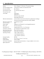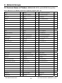
1
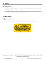
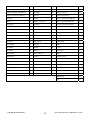
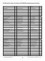
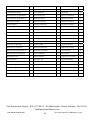
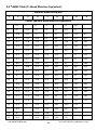
USER MANUAL FLIR MODEL MR160 IMAGING MOISTURE METER 99 Washington Street Melrose, MA 02176 Phone 781-665-1400 Toll Free 1-800-517-8431 Visit us at www.TestEquipmentDepot.com Table of Contents 1. DISCLAIMERS 4 4 4 4 4 1.1 Copyright 1.2 Quality Assurance 1.3 Documentation 1.4 Disposal of Electronic Waste 2. SAFETY 5 5 5 2.1 Safety Notes 2.2 Laser Safety 3. INTRODUCTION 6 6 3.1 Key Features 4. METER AND MENU ICON DESCRIPTIONS 7 7 8 9 4.1 Meter Parts 4.2 Control Buttons 4.3 Menu Icons Overview 5. OPERATION 5.1 Powering the Meter 5.1.1 Auto Power OFF (APO) 5.2 Moisture Measurements and Display Overview 5.2.1 Moisture Measurement Overview 5.2.2 Display Overview 5.2.3 IMAGE Mode 5.2.4 MOISTURE Mode 5.2.5 Internal Moisture Sensor Measurements (Pinless) 5.2.6 External Moisture Probe (Pin) Measurements 5.2.7 Reference Mode Moisture Measurements 5.3 Thermal Imager (IR) 5.4 SETTINGS Mode 5.5 Screen Capture 5.6 Combination Mode: Held Thermal Image with Moisture Reading 5.7 High Moisture Alarm FLIR MR160 USER GUIDE 2 10 10 10 10 10 10 11 12 12 13 13 14 16 16 17 18 Document Identifier: MR160‐en‐US_AA 6. MAINTENANCE 19 19 19 19 6.1 Cleaning 6.2 Battery Charging 6.2.1 Disposal of Electronic Waste 7. SPECIFICATIONS 20 8. TECHNICAL SUPPORT 21 9. MATERIAL GROUPS 22 22 24 26 9.1 Common Names of Timbers (BS888/589:1973) with MR160 Group Nos. 9.2 Botanical names of timbers with MR160 program group numbers 9.3 %WME Table (% Wood Moisture Equivalent) 10. WARRANTIES 10.1 FLIR Test & Measurement Imaging Product 2 year/10 year Limited Warranty FLIR MR160 USER GUIDE 3 27 27 Document Identifier: MR160‐en‐US_AA 1. Disclaimers 1.1 Copyright © 2015, FLIR Systems, Inc. All rights reserved worldwide. No parts of the software including source code may be reproduced, transmitted, transcribed or translated into any language or computer language in any form or by any means, electronic, magnetic, optical, manual or otherwise, without the prior written permission of FLIR Systems. The documentation must not, in whole or part, be copied, photocopied, reproduced, translated or transmitted to any electronic medium or machine readable form without prior consent, in writing, from FLIR Systems. Names and marks appearing on the products herein are either registered trademarks or trademarks of FLIR Systems and/or its subsidiaries. All other trademarks, trade names or company names referenced herein are used for identification only and are the property of their respective owners. 1.2 Quality Assurance The Quality Management System under which these products are developed and manufactured has been certified in accordance with the ISO 9001 standard. FLIR Systems is committed to a policy of continuous development; therefore we reserve the right to make changes and improvements on any of the products without prior notice. 1.3 Documentation To access the user manuals, extended warranty registration, firmware updates, and notifications go to the Download tab at: http://support.flir.com. In the download area you will also find the latest releases of manuals for our other products, as well as manuals for our historical and obsolete products. The extended warranty page can also be found at www.Flir.com/testwarranty. 1.4 Disposal of Electronic Waste As with most electronic products, this equipment must be disposed of in an environmentally friendly way, and in accordance with existing regulations for electronic waste. FLIR MR160 USER GUIDE 4 Document Identifier: MR160‐en‐US_AA 2. Safety 2.1 Safety Notes Before operating the device, you must read, understand, and follow all instructions, dangers, warnings, cautions, and notes. FLIR Systems reserves the right to discontinue models, parts or accessories, and other items, or to change specifications at any time without prior notice. 2.2 Laser Safety Warning Statement Do not look directly into the laser beam. The laser beam can cause eye irritation. Test Equipment Depot - 800.517.8431 - 99 Washington Street Melrose, MA 02176 TestEquipmentDepot.com FLIR MR160 USER GUIDE 5 Document Identifier: MR160‐en‐US_AA 3. Introduction Thank you for selecting the FLIR MR160 Imaging Moisture Meter. The MR160 integrates high quality thermal imaging technology with the best in class moisture detection and quantification. Quickly scan using our Lepton® thermal imager and find the problem areas to investigate further with built in moisture sensing technology. The MR160 offers two methodologies for moisture measurement an internal, non‐ invasive, pinless moisture sensor and an external pin‐based probe. The MR160 also features a capture function that saves the measurements and images. The saved data can be transferred to a PC using the USB cable; reports can be generated with FLIR TOOLS PC Software. This device is shipped fully tested and calibrated and, with proper use, will provide years of reliable service. 3.1 Key Features FLIR Lepton® microbolometer Focal Plane Array (FPA) with integrated shutter delivers best in class thermal imaging Quickly indicate the moisture content of materials using pin‐less technology without damaging the test surface Easy to read, color display monitor with intuitive graphical interface featuring tool tips in local languages View Thermal Images, Moisture readings, or combine the two on one screen External Pin Probe included for resistive moisture measurements Nine (9) Material Group selections for pin‐based readings Audible and Visual High Moisture Alarm Capture and review Thermal Image screen shots Laser pointer and display cross‐hairs for better targeting Rugged and Reliable (over‐mold Design) Internal rechargeable battery with USB based international charger Dedicated measurement modes with large digits and color Bargraph File management, Image Review, and Report Generation with Free FLIR TOOLS software for PC FLIR MR160 USER GUIDE 6 Document Identifier: MR160‐en‐US_AA 4. Meter and Menu Icon Descriptions 4.1 Meter Parts 1 1. Color Graphical Display 2. Screen Capture button 3. Four (4) Navigation buttons (rim) 4. Select button (center) 5. Back button 6. Laser Pointer / Cross‐hairs button 7. Power button 8. Ext. Probe jack / USB port / Charging LED 9. Laser pointer lens (back) 5 6 2 3 4 7 8 10. Thermal imaging lens (back) 11. Internal Pinless Moisture sensor (back) 12. USB Port (bottom) 9 10 13. External Probe Jack (bottom) 14. Battery Charging LED status lamp (bottom) 11 Fig. 4‐1 Meter Description 12 14 13 FLIR MR160 USER GUIDE 7 Document Identifier: MR160‐en‐US_AA 4.2 Control Buttons Press to save a ‘screen‐shot’. An image file‐name will appear on the screen (FLIRxxxx.bmp). Use the ‘Image Review Mode’ to scroll images on‐ screen. Use the USB interface to transfer images to computer or other compatible device. Press to back out of (return from) a menu screen. Press to activate laser pointer/cross‐hairs in thermal imaging modes. Press to power the meter ON. Press and hold to power the meter OFF. Press the Select button (center) to access the Main Menu. Use this button to select items from within the menu structure. Use the four outer navigation (rim) buttons to move up‐down‐left‐right. FLIR MR160 USER GUIDE 8 Document Identifier: MR160‐en‐US_AA 4.3 Menu Icons Overview The Menu Icons are outlined below and referred to more thoroughly throughout this guide. The center Select button and the four (4) Navigation buttons are used to open and select the various modes of operation available from the menus. Icons 1 through 5 in the diagram below make up the Main Menu icons (Image Review, Image mode, Moisture mode, Settings utility, and Help screen, respectively). Press the Select button to open the Main Menu and view these icons. Icons 6 through 8 are shown in the Image mode menu (Thermal Image only, Thermal Image plus Moisture readings, and Moisture‐only icon, respectively). Press icon 2 to view the Image mode list. Items 9 through 12 are the Moisture mode selection icons (Material Group, Pin mode, Pinless mode, and Set Reference mode, respectively). Press icon 3 to view the Moisture mode icon list. A blue dot is shown to the left of the pin icon (10) or the pinless icon (11), depending on which one is selected. The numbered list below calls out each icon in Fig. 4‐2: 1. Image Review icon (view stored images) 2. Image mode icon: Press to open the Image mode selection list (6, 7, and 8) 3. Moisture mode icon: Press to open the Moisture mode selection list (9~12) 4. Settings mode: Press to access LANGUAGE, DATE/TIME, AUTO POWER OFF, and INFORMATION utilities. 5. Help screen 6. IR Thermal image only mode 7. IR + Moisture mode 8. Moisture‐only mode 9. Material Groups (pin mode only) 6 7 8 1 2 9 10 11 12 3 4 5 Fig. 4‐2 Menu Icons 10. Pin mode (for external probe use) 11. Pinless (for internal sensor use) 12. ‘Set Reference’ mode (for pinless mode only) FLIR MR160 USER GUIDE 9 Document Identifier: MR160‐en‐US_AA 5. Operation 5.1 Powering the Meter 1. Press the Power button momentarily to switch the meter ON. 2. 3. Press and hold the Power button for > 1 second to switch the meter OFF. If the battery status indicator shows that the battery voltage is low, or if the meter does not power on, charge the battery. See section 6.2 Battery Charging. The battery status indicator is visible in the Main Menu (press the center Menu button to access the Main Menu). 5.1.1 Auto Power OFF (APO) The meter switches OFF automatically after a programmed period of inactivity. The meter beeps several times several seconds before powering off. Press any button to reset the APO timer. To disable APO, or to change the APO time‐out value, use the SETTINGS utility accessible from the Main Menu. The default time‐out is 20 minutes. 5.2 Moisture Measurements and Display Overview 5.2.1 Moisture Measurement Overview Moisture measurements can be performed using either the internal pinless moisture sensor (rear) or by connecting an external pin probe. NOTE: Objects in close proximity to the internal pinless moisture sensor (located on the rear of the unit) will affect the reading on the display; Keep hands and fingers clear of the sensor when taking measurements. The internal moisture sensor detects moisture to a depth of approximately 0.75” (19mm). The actual depth will vary depending upon the amount of moisture, the material under test, surface roughness, and other factors. Moisture readings are shown on the display (digitally and with bar graph) in the Moisture‐only mode or in small digits (upper left hand corner) in IR + Moisture mode. See Fig. 5‐1 and Fig. 5‐2. Pinless measurement readings are relative scaled (0~100) while pin‐based readings are represented in %WME (percent wood moisture equivalent) 0~100%. Use the center Select button and the four outer Navigation buttons to access menus, scroll, and select modes. 5.2.2 Display Overview Most of the MR160 operations are represented in the icons and displays shown in Fig. 5‐1 and Fig. 5‐2 below. Other operations are covered in the context of each section of this User Guide. Test Equipment Depot - 800.517.8431 - 99 Washington Street Melrose, MA 02176 TestEquipmentDepot.com FLIR MR160 USER GUIDE 10 Document Identifier: MR160‐en‐US_AA 5 6 7 4 3 10 11 8 2 9 1 Fig. 5‐1 IR + Moisture Image Fig. 5‐2 Moisture reading only 1. IR Thermal Image 2. Cross‐hairs (press Laser button to activate) 3. Reference Value (see Set Reference mode information in Sections 5.2.3 and 5.2.6) 4. High Moisture Alarm setting (see Sections 5.4 and 5.7 for details) 5. Pin‐based moisture reading 0~100 %WME (Wood Moisture Equivalent) or relative reading (0~100) when using the pinless, internal Moisture Sensor 6. Pinless icon 7. Laser pointer active icon (press Laser button to switch Laser pointer ON/OFF) 8. Moisture reading ‐ digital format 9. Moisture reading ‐ bargraph format (appears blue when in non‐Alarm state) 10. High Moisture Alarm setting (see Sections 5.4 and 5.7) 11. Set Reference value (see Set Reference mode in Sections 5.2.3 and 5.2.6); pinless mode only 5.2.3 IMAGE Mode Press the Select button to access the Main Menu and then select the IMAGE mode icon (1). Refer to Fig. 5‐3. Choose Thermal IR Image‐only mode (2), Thermal IR image + Moisture reading mode (3), or Moisture‐only mode (4). 2 1. Image mode icon from the Main Menu 2. IR Thermal Image mode only 3. IR Thermal Image + Moisure reading 4. Moisture reading only FLIR MR160 USER GUIDE 3 4 1 Fig. 5‐3 Image mode icons 11 Document Identifier: MR160‐en‐US_AA 5.2.4 MOISTURE Mode From the Main Menu select the MOISTURE mode icon (1). Refer to Fig. 5‐4. Then choose from the four Moisture mode options (items 2, 3, 4, and 5) as described below. 1. Moisture Mode Icon from the Main Menu 2. MATERIAL GROUPS Select a material wood group that best matches the material under test. This applies only for external pin‐based probe use; Use the navigation buttons to scroll through the group list and use the Select button to choose the group. The selected group will show a blue dot. See the Material Wood Group List Appendix in Section 9. 2 3 4 5 3. PIN MODE PIN mode must be selected when the external pin‐ based probe is used. Note the pin icon (3) on the upper left of the main display when selected. 4. PINLESS MODE 1 PINLESS mode must be selected when using the internal sensor. Note the pinless icon (4) on the upper left of the main display when selected. Fig. 5‐4 Moisture mode icons 5. SET REFERENCE MODE SET REFERENCE is used to compare the displayed readings against a stored reference measurement (see Section 5.2.7 Set Reference Mode). This mode applies only to readings taken with the pinless internal sensor. 5.2.5 Internal Moisture Sensor Measurements (Pinless) 1. Follow the steps in Section 5.2.1 through 5.2.4 and select the Pinless mode. 2. Place the internal moisture sensor (back) on the surface of the material to be tested. Apply light pressure to ensure that the internal sensor is completely flat against the surface of the material under test. 3. The relative moisture reading is displayed on the main display in the upper left hand corner (IR + Moisture mode) or as bargraph with accompanying digits (Moisture‐only mode). Refer to example screens shown in Fig. 5‐1 and Fig. 5‐2. 4. For best results, keep hands, surfaces, and objects away from the rear internal moisture sensor area when taking measurements. FLIR MR160 USER GUIDE 12 Document Identifier: MR160‐en‐US_AA 5.2.6 External Moisture Probe (Pin) Measurements 1. Follow the steps in Section 5.2.1 through 5.2.4 and select Pin mode from the MOISTURE mode options. 2. Connect the external pin probe to the meter’s EXT jack on the bottom of the meter (under the protective flap). 3. Select the appropriate Material Group as described in Section 5.2.4 (see Section 9 for the Material Group Appendices). Note: Use Group 9 for building materials. 4. Press the pins into the material under test. 5. The moisture reading is displayed on the main display (in %WME) in the upper left hand corner (IR + Moisture mode) or as a bargraph with accompanying digits (Moisture‐only mode). Refer to example screens shown in Fig. 5‐1 and Fig. 5‐2. 5.2.7 Reference Mode Moisture Measurements 1. Follow the steps in Section 5.2.1 through 5.2.4 and select SET REFERENCE from the MOISTURE mode options. This mode is only available for pinless measurements (internal sensor). 2. When the SET REFERENCE mode is selected a new display line will appear preceded by a delta (triangle) symbol. The digits next to the triangle symbol indicate the reference value (the measurement recorded when the SET REFERENCE mode is selected). Refer to example screens shown in Fig. 5‐1 and Fig. 5‐2. 3. All measurements taken subsequently will be relative to the reference value. For example, if the reference value is ‘10’ (representing the driest area of the material under test) and a measurement of ‘50’ is taken (in an area with higher moisture content), the measurement line will show ‘40’ (50 – 10 = 40). As implied, this mode is useful for comparing wet areas to a dry area reference. 4. The reference value is displayed on the main display in the upper left hand corner (IR + Moisture mode) or to the right of the bargraph (Moisture‐only mode). Refer to example screens shown in Fig. 5‐1 and Fig. 5‐2. 5. To remove the reference value and exit the mode: Remove the meter sensor from the area under test, so that the sensor is no longer touching a surface and is clear of any objects (keep hands away from the sensor also), and then press the Set Reference icon again. The reference value will no longer be visible on the meter display. FLIR MR160 USER GUIDE 13 Document Identifier: MR160‐en‐US_AA 5.3 Thermal Imager (IR) The full screen IR Thermal Imager is active in the IR ‐only mode modes (selectable from the IMAGE mode icon and in the IR + Moisture in the Main Menu). The Thermal Imager lens is located on the back of the meter. Face the lens toward the area of interest and view the image on the meter display. Hot to cold temperatures for images are represented by this color palette progression: white>grey>black>blue>white. See the color palette example below. The left of the scale is the hottest pixel in the frame, and the right of the scale is the coldest. Wet areas will be colder than the background and will, therefore, show up as blue; lighter blues are ‘wetter’ than darker blues. Fig. 5‐5 Thermal Image ‘Color Palette’ Fig. 5‐6 Thermal IR Image example FLIR MR160 USER GUIDE 14 Document Identifier: MR160‐en‐US_AA When the Laser Pointer button is pressed to activate the laser pointer, the display cross‐hairs also switch on, for additional targeting flexibility. 1. Laser icon (Press Laser button to activate) 2. Battery status icon is visible when a program menu is accessed 3. IR Thermal Image 4. Cross‐hairs (Press Laser button to activate) 5. Tool tips 6. Image mode icons row (IR Thermal Image‐only mode, IR Thermal Image + Moisture reading mode, and Moisture‐only mode, respectively) 7. Image mode menu access icon 1 2 3 Fig. 5‐7‐ Thermal IR Image 4 5 6 7 Test Equipment Depot - 800.517.8431 - 99 Washington Street Melrose, MA 02176 TestEquipmentDepot.com FLIR MR160 USER GUIDE 15 Document Identifier: MR160‐en‐US_AA 5.4 SETTINGS Mode Access the SETTINGS mode by pressing the Select button and choosing the SETTINGS mode icon (shown above). The SETTINGS mode options are described below: 1. LANGUAGE. From the SETTINGS menu, scroll to Language and press the Select button. Use the four Navigation buttons and the Select button to choose the desired language. The selected language will show a blue dot to its right. Press the Select button to save the to cancel and return. value and return to SETTINGS menu or press the back button 2. DATE & TIME. From the SETTINGS menu, scroll to Date & Time and press the Select button. Use the four Navigation buttons and the Select button to program the current date and time (year, month, day, hour, and minute). Press the Select button to save the to cancel and return. value and return to SETTINGS menu or press the back button 3. ALARM. From the SETTINGS menu, scroll to Alarm and press the Select button. Use the navigation buttons and the Select button to set the high alarm threshold and to switch the alarm ON/OFF. Refer to Section 5.7 for Alarm mode details. The Alarm can be used in pin or pinless mode of operation. Press the Select button to save the value and return to to cancel and return. the SETTINGS menu or press the back button 4. AUTO POWER OFF. From the SETTINGS menu, scroll to Auto Power OFF and then use the Select button to scroll through the available options (1, 5, 20 minutes, or OFF). Navigate to exit the SETTINGS mode. to another SETTINGS option or press the back button 5. METER INFORMATION. From the SETTINGS menu, scroll to Meter Information and press the Select button to view the Model, Software Version, and Last Calibration Date to return to the SETTINGS menu. information. Press the back button 5.5 Screen Capture Pressing the Image Capture button records the current MR160 screen (with minor restrictions). After one second, an image file‐name will appear on the screen (FLIRxxxx.bmp). Images are saved in .bmp (bitmap) 16‐bit format. Images can be accessed on the MR160 screen using the Image Review icon available in the Main Menu. Then scroll the images using the navigation buttons. Images can also be transferred to computer or other compatible device using the MR160 USB port (bottom of meter, under flap) and supplied USB cable. FLIR MR160 USER GUIDE 16 Document Identifier: MR160‐en‐US_AA 5.6 Combination Mode: Held Thermal Image with Moisture Reading The MR160 offers an advanced feature that allows the user to ‘freeze’ a thermal image and continue taking moisture readings. The ‘held’ thermal image, with continuous moisture reading shown on the same screen, can then be captured as explained in section 5.5 above. 1. Enter the IR + Moisture Image mode (refer to Section 5.2.3 Image Mode). 2. Hold the Capture button until crosshairs appear and laser are visible (Fig. 5‐8a) 3. While continuing to hold the Capture button, aim the laser at the measurement spot 4. Release the Capture button. The image will freeze but the moisture reading will flash and continue to update as it waits for a measurement. 5. Press the Select button to make a measurement and capture (save) the image which will include the moisture reading (Fig. 5‐8b) or press the Back button to cancel and return to the normal operating mode. Fig. 5‐8a Laser and Cross‐hairs visible; Aim the Laser at the test surface Fig. 5‐8b Saved image with Target area and Moisture reading FLIR MR160 USER GUIDE 17 Document Identifier: MR160‐en‐US_AA 5.7 High Moisture Alarm The MR160 offers a High Moisture Alarm utility where an audible and visual alert activates when the moisture reading exceeds the programmed high limit. 1. Press the Select button to access the Main Menu 2. Select the SETTINGS mode 3. Scroll to ALARM and press the Select button to open the Alarm programmer 4. Use the Navigation and Select buttons to switch the alarm ON or OFF and to set the threshold from 0% to 100% 5. Press the Select button to return to the SETTINGS mode and save the value or press the back button to cancel and to return to the normal operating mode 6. When the High Alarm is set ON, the main display will show the alarm bell icon (shown above) and the High Alarm threshold value. Refer to example screens shown in Fig. 5‐1 and Fig. 5‐2. 7. When the measurement exceeds the threshold, the text for the actual measurement reading will appear red in color and will flash; the beeper will also sound. Note that in the Moisture‐only mode, the bargraph turns red when the Alarm threshold is exceeded. Refer to the example screens in Fig. 5‐1 and Fig. 5‐2. 8. To switch the alarm OFF, press the Select button and then select SETTINGS from the Main Menu FLIR MR160 USER GUIDE from the Main Menu 18 Document Identifier: MR160‐en‐US_AA 6. Maintenance 6.1 Cleaning Clean the meter with a damp cloth and mild detergent; do not use abrasives or solvents. 6.2 Battery Charging 1. 2. 3. 4. The internal battery is not user serviceable. Connect the meter to an AC source or a computer USB port using the supplied USB charger cable. The USB port is located on the bottom of the meter, under the protective flap, next to the EXT Probe jack. While the meter is charging, a blue LED (bottom of meter under protective flap) indicates that charging is successfully taking place. View the battery status icon on the upper left hand corner of the meter’s display when a program menu is active. 6.2.1 Disposal of Electronic Waste As with most electronic products, this equipment must be disposed of in an environmentally friendly way, and in accordance with existing regulations for electronic waste. FLIR MR160 USER GUIDE 19 Document Identifier: MR160‐en‐US_AA 7. Specifications Display 320 x 240 pixel 2.3” 64K color TFT graphical display Thermal imaging camera FLIR Lepton® module, microbolometer FPA Thermal resolution 80 x 60 pixels Thermal field of view 51° horizontal; 38° vertical Thermal frame rate 9 Hz Laser diode Visible light Safety class 2 Maximum power 1.0mW Wavelength 650 ±20nm Moisture measurements Internal pinless sensor measurements 0 to 100 (relative readings) Moisture sampling rate 2 samples per second External pin based measurements 0 to 100% (%WME) Internal memory 4GB Power supply 3000mAh (2 x 1500mAh Li‐ion rechargeable batteries) Battery life Auto Power OFF 10 hours minimum Low battery indicator Programmable: OFF, 1, 5, or 20 minutes is displayed in the Main Menu screen Operating temperature 32 to 122 °F (0 to 50 °C) Storage temperature 14 to 140°F (‐10 to 60°C) Operating humidity ≤ 90%, 32‐86°F (0‐30°C) ≤ 75%, 86‐104°F (30‐40°C) ≤ 45%, 104‐122°F (40‐50°C) Storage humidity Dimensions Product Weight 90% RH 5.5 × 2.9 × 1.7″ (14 × 7.2 × 4.2 cm) 10.6oz. (300g) Certification standards EN61326 (EMC), EN61010 (Battery + Charger), EN60825‐1 Class 2 (Laser) Agency approvals FCC Class B, CE, UL Test Equipment Depot - 800.517.8431 - 99 Washington Street Melrose, MA 02176 TestEquipmentDepot.com FLIR MR160 USER GUIDE 20 Document Identifier: MR160‐en‐US_AA FLIR MR160 USER GUIDE 21 Document Identifier: MR160‐en‐US_AA 9. Material Groups 9.1 Common Names of Timbers (BS888/589:1973) with MR160 Group Nos. Note: GROUP 9 is for Building materials: Plywood, drywall, OCD, etc. Abura 4 Gurjun 1 Pine, American Long Leaf 3 Afara 1 Hemlock, Western 3 Pine, American Pitch 3 Aformosa 6 Hiba 8 Pine, Bunya 2 Afzelia 4 Hickory 5 Pine, Caribbean Pitch 3 Agba 8 Hyedunani 2 Pine, Corsican 3 Amboyna 6 Iroko 5 Pine, Hoop 3 Ash, American 2 Ironbank 2 Pine, Huon 2 Ash, European 1 Jarrah 3 Pine, Japanese Black 2 Ash, Japanese 1 Jelutong 3 Pine, Kauri 4 Ayan 3 Kapur 1 Pine, Lodgepole 1 Baguacu, Brazilian 5 Karri 1 Pine, Maritime 2 Balsa 1 Kauri, New Zealand 4 Pine, New Zealand White 2 Banga Wanga 1 Kauri, Queensland 8 Pine, Nicaraguan Pitch 3 Basswood 6 Keruing 5 Pine, Parana 2 Beech, European 3 Kuroka 1 Pine, Ponderosa 3 Berlina 2 Larch, European 3 Pine, Radiata 3 Binvang 4 Larch, Japanese 3 Pine, Red 2 Birch, European 8 Larch, Western 5 Pine, Scots 1 Birch, Yellow 1 Lime 4 Pine, Sugar 3 Bisselon 4 Loliondo 3 Pine, Yellow 1 Bitterwood 5 Mahogany, African 8 Poplar, Black 1 Blackbutt 3 Mahogany, West Indian 2 Pterygota, African 1 Bosquiea 1 Makore 2 Pyinkado 4 Boxwood, Maracaibo 1 Mansonia 2 Queensland Kauri 8 Camphorwood, E African 3 Maple, Pacific 1 Queensland Walnut 3 Canarium, African 2 Maple, Queensland 2 Ramin 6 Cedar, Japanese 2 Maple, Rock 1 Redwood, Baltic (European) 1 Cedar, West Indian 8 Maple, Sugar 1 Redwood, Californian 2 Cedar, Western Red 3 Matai 4 Rosewood, Indian 1 Cherry, European 8 Meranti, Red (dark/light) 2 Rubberwood 7 Chestnut 3 Meranti, White 2 Santa Maria 7 Coachwood 6 Merbau 2 Sapele 3 FLIR MR160 USER GUIDE 22 Document Identifier: MR160‐en‐US_AA Cordia, American Light 5 Missanda 3 Sen 1 Cypress, E African 1 Muhuhi 8 Seraya, Red 3 Cypress, Japanese (18‐28%mc) 3 Muninga 6 Silky Oak, African 3 Cypress, Japanese (8‐18%mc) 8 Musine 8 Silky Oak, Australian 3 Dahoma 1 Musizi 8 Spruce, Japanese (18‐28%mc) 3 Danta 3 Myrtle, Tasmanian 1 Spruce, Japanese (8‐18%mc) 8 Douglas Fir 2 Naingon 3 Spruce, Norway (European) 3 Elm, English 4 Oak, American Red 1 Spruce, Sitka 3 Elm, Japanese Grey Bark 2 Oak, American White 1 Sterculia, Brown 1 Elm, Rock 4 Oak, European 1 Stringybark, Messmate 3 Elm, White 4 Oak, Japanese 1 Stringybark, Yellow 3 Empress Tree 8 Oak, Tasmanian 3 Sycamore 5 Erimado 5 Oak, Turkey 4 Tallowwood 1 Fir, Douglas 2 Obeche 6 Teak 5 Fir, Grand 1 Odoko 4 Totara 4 Fir, Noble 8 Okwen 2 Turpentine 3 Gegu, Nohor 7 Olive, E African 2 Utile 8 Greenheart 3 Olivillo 6 Walnut, African 8 Guarea, Black 8 Opepe 7 Walnut, American 1 Guarea, White 7 Padang 1 Walnut, European 3 Gum, American Red 1 Padauk, African 5 Walnut, New Guinea 2 Gum, Saligna 2 Panga Panga 1 Walnut, Queensland 3 Gum, Southern 2 Persimmon 6 Wandoo 8 Gum, Spotted 1 Pillarwood 5 Wawa 6 Whitewood 3 Yew 3 FLIR MR160 USER GUIDE 23 Document Identifier: MR160‐en‐US_AA 9.2 Botanical names of timbers with MR160 program group numbers Abies alba 1 Eucalyptus acmenicides 3 Picea jezoensis (8‐ 18%mc) 8 Abies grandis 1 Eucalyptus crebra 2 Picea sitchensis 3 Abies procera 8 Eucalyptus diversicolor 1 Pinus caribaea 3 Acanthopanex ricinifolius 1 Eucalyptus globulus 2 Pinus contorta 1 Acer macrophyllum 1 Eucalyptus maculate 1 Pinus lampertiana 3 Acer pseudoplatanus 5 Eucalyptus marginata 3 Pinus nigra 3 Acer saccharum 1 Eucalyptus microcorys 1 Pinus palustris 3 Aetoxicon punctatum 6 Eucalyptus obliqua 3 Pinus pinaster 2 Aformosia elata 6 Eucalyptus pilularis 3 Pinus ponderosa 3 Afzelia spp 4 Eucalyptus saligna 2 Pinus radiate 3 Agathis australis 4 Eucalyptus wandoo 8 Pinus spp 2 Agathis palmerstoni 8 Fagus sylvatica 3 Pinus strobus 1 Agathis robusta 8 Flindersia brayleyana 2 Pinus sylvestris 1 Amblygonocarpus andogensis 1 Fraxinus Americana 2 Pinus thunbergii 2 1 Pipadeniastrum africanum 1 Amblygonocarpus obtusungulis 1 Fraxinus excelsior Araucaria angustifolia 2 Fraxinus japonicus 1 Piptadenia africana 1 Araucaria bidwilli 2 Fraxinus mardshurica 1 Podocarpus dacrydiodes 2 Araucaria cunninghamii 3 Gonystylus macrophyllum 6 Podocarpus spicatus 3 Berlinia grandiflora 2 Gossweilodendron balsamiferum 8 Podocarpus totara 4 Berlinia spp 2 Gossypiospermum proerox 1 Populus spp 1 Betula alba 8 Grevillea robusta 3 Prunus avium 8 Betula alleghaniensis 8 Guarea cedrata 7 Pseudotsuga menzesii 2 Betula pendula 8 Guarea thomsonii 8 Pterocarpus angolensis 6 Betula spp 8 Guibortia ehie 2 Pterocarpus indicus 6 Bosquiera phoberos 1 Hevea brasilensis 7 Pterocarpus soyauxii 5 Brachylaena hutchinsii 8 Intsia bijuga 2 Pterygota bequaertii 1 Brachystegia spp 2 Juglans nigra 1 Quercus cerris 4 Calophyllum brasiliense 7 Juglans regia 3 Quercus delegatensis 3 Canarium schweinfurthii 2 Khaya ivorensis 8 Quercus gigantean 3 Cardwellia sublimes 3 Khaya senegalensis 4 Quercus robur 1 Carya glabra 5 Larix decidua 3 Quercus spp 1 Cassipourea elliotii 5 Larix kaempferi 3 Ricinodendron heudelotti 5 Cassipourea melanosana 5 Larix leptolepis 3 Sarcocephalus diderrichii 7 FLIR MR160 USER GUIDE 24 Document Identifier: MR160‐en‐US_AA Castanea sutiva 3 Larix occidentalis 5 Scottellia coriacea 4 Cedrela odorata 8 Liquidamper styraciflua 1 Sequoia sempervirens 2 Ceratopetalum apetala 6 Lovoa klaineana 8 Shorea spp 2 Chamaecyparis spp (18‐28%mc) 3 Lovoa trichiloides 8 Sterculia rhinopetala 1 Chamaecyparis spp (8‐18%mc) 8 Maesopsis eminii 8 Swietenia candollei 1 Chlorophora excelsa 5 Mansonia altissima 2 Swietenia mahogani 2 Cordia alliodora 5 Millettia stuhimannii 1 Syncarpia glomulifera 3 Croton megalocarpus 8 Mimusops heckelii 2 Syncarpia laurifolia 3 Cryptomelia japonica 2 Mitragyna ciliata 4 Tarrietia utilis 3 Cupressus spp 1 Nauclea diderrichii 7 Taxus baccata 3 Dacryium franklinii 2 Nesogordonia papaverifera 3 Tectona grandis 5 Dalbergia latifolia 1 Nothofagus cunninghamii 1 Terminalia superba 1 Diospyros virginiana 6 Ochroma pyramidalis 1 Thuja plicata 3 Dipterocarpus (Keruing) 5 Ocotea rodiaei 3 Thujopsis dolabrat 8 Dipterocarpus zeylanicus 1 Ocotea usambarensis 3 Tieghamella heckelii 2 Distemonanthus benthamianus 3 Octomeles sumatrana 4 Tilia americana 6 Dracontomelium mangiferum 2 Olea hochstetteri 2 Tilia vulgaris 4 Dryobanalops spp 1 Olea welwitschii 3 Triploehiton scleroxylon 6 Dyera costulata 3 Palaquium spp 1 Tsuga heterophylia 3 Endiandra palmerstoni 3 Paulownia tomentosa 8 Ulmus americana 4 Entandrophragma angolense 7 Pericopsis elata 6 Ulmus procera 4 Entandrophragma cylindricum 3 Picaenia excelsa 3 Ulmus thomasii 4 Entandrophragma utile 8 Picea abies 3 Xylia dolabriformis 4 Erythrophleum spp 3 Picea jezoensis (18‐28%mc) 3 Zelkova serrata 2 Test Equipment Depot - 800.517.8431 - 99 Washington Street Melrose, MA 02176 TestEquipmentDepot.com FLIR MR160 USER GUIDE 25 Document Identifier: MR160‐en‐US_AA 9.3 %WME Table (% Wood Moisture Equivalent) Material Wood Group Nos. 1 2 3 4 5 6 7 8 9 %WME (percent wood moisture equivalent) 7 8.2 9 8 7.1 7 11 10.5 ‐ 8 10 10.5 9.3 7.5 7.4 11.5 11 ‐ 9 10.8 10.9 9.7 7.9 8.1 12.1 11.6 8.5 10 11.7 11.5 10.4 8.6 8.8 12.7 12.2 9.4 11 12.7 12.6 11.3 9.5 9.7 13.4 13.4 10.5 12 13.6 13.7 12.1 10.5 10.5 14 14.3 11.5 13 14.5 14.5 12.7 11.2 11.2 14.5 15.1 12.5 14 15.3 15.5 13.4 11.8 11.8 15 16 13.5 15 16.3 16.7 14.1 12.5 12.6 15.6 17 14.4 16 16.9 17.5 14.8 13 13.2 16 17.7 14.9 17 17.7 18.8 15.7 14.3 13.9 16.6 18.5 15.3 18 18.2 19.7 16.3 15 14.5 17 19.1 16.1 19 19 21 16.9 15.9 15.2 17.6 20 16.7 20 20 22.6 17.8 16.9 16.1 18.4 21.3 17.2 21 20.8 23.5 18.5 17.6 16.8 19.1 22.3 18.3 22 21.5 24.5 19.3 18.3 17.4 19.7 23.2 19.1 23 22.9 26.4 20.2 19.8 18.6 21.2 25.3 19.9 24 23.5 27.4 20.8 20.4 19 22 25.8 20.5 25 24.2 27.8 21.2 21 19.4 22.7 26.3 ≈23 26 25.3 29 22.4 22.3 20.1 23.9 27.3 ‐ 27 26.5 ‐ 23.3 23.4 20.8 24.7 28.1 ‐ 28 28 ‐ 24.4 24.8 21.7 25.9 ‐ ‐ 29 29.6 ‐ 25.6 26.3 22.9 27.1 ‐ ‐ FLIR MR160 USER GUIDE 26 Document Identifier: MR160‐en‐US_AA 10. Warranties 10.1 FLIR Test & Measurement Imaging Product 2 year/10 year Limited Warranty Congratulations! You (the “Purchaser”) are now the owner of a world‐class FLIR Imaging Test and Measurement product. A qualifying FLIR Imaging Test and Measurement product (the “Product”) purchased either directly from FLIR Commercial Systems Inc. and affiliates (FLIR) or from an authorized FLIR distributor that Purchaser registers on‐line with FLIR is eligible for coverage under FLIR’s industry‐leading 2‐10 Limited Warranty, subject to the terms and conditions in this document. This warranty only applies to purchases of Qualifying Products (see below) purchased after July 2014 and only to the original Purchaser of the Product. PLEASE READ THIS DOCUMENT CAREFULLY; IT CONTAINS IMPORTANT INFORMATION ABOUT THE PRODUCTS THAT QUALIFY FOR COVERAGE UNDER THE 2‐10 LIMITED WARRANTY, PURCHASER’S OBLIGATIONS, HOW TO ACTIVATE THE WARRANTY, WARRANTY COVERAGE, AND OTHER IMPORTANT TERMS, CONDITIONS, EXCLUSIONS AND DISCLAIMERS. 1. PRODUCT REGISTRATION. To qualify for FLIR’s 2‐10 Limited Warranty, the Purchaser must fully register the Product directly with FLIR on‐line at www.flir.com WITHIN Sixty (60) DAYS of the date the Product was purchased by the first retail customer (the “Purchase Date”). PRODUCTS THAT ARE NOT REGISTERED ON‐LINE WITHIN Sixty (60) DAYS OF THE PURCHASE DATE OR PRODUCTS WHICH DO NOT QUALIFY FOR THE 2‐10 WARRANTY WILL HAVE A LIMITED ONE YEAR WARRANTY FROM THE DATE OF PURCHASE. 2. QUALIFYING PRODUCTS. Upon registration, a list of thermal Imaging Test and Measurement Products that qualify for coverage under FLIR’s 2‐10 Warranty can be found at www.flir.com/testwarranty 3. WARRANTY PERIODS. The 2‐10 Limited Warranty has two separate periods of warranty coverage (the “Warranty Period”), depending on the Imaging Test and Measurement Product part: Product components (excluding thermal imaging sensor) are warranted for a period of two (2) years from the Purchase Date; Thermal imaging sensor is warranted for a period of ten (10) years from the Purchase Date. Any Product that is repaired or replaced under warranty is covered under this 2‐10 Limited Warranty for one hundred eighty days (180) days from the date of return shipment by FLIR or for the remaining duration of the applicable Warranty Period, whichever is longer. 4. LIMITED WARRANTY. In accordance with the terms and conditions of this 2‐10 Limited Warranty, and except as excluded or disclaimed in this document, FLIR warrants, from the Purchase Date, that all fully registered Products will conform to FLIR’s published Product specifications and be free from defects in materials and workmanship during the applicable Warranty Period. PURCHASER’S SOLE AND EXCLUSIVE REMEDY UNDER THIS WARRANTY, AT FLIR’S SOLE DISCRETION, IS THE REPAIR OR REPLACEMENT OF DEFECTIVE PRODUCTS IN A MANNER, AND BY A SERVICE CENTER, AUTHORIZED BY FLIR. IF THIS REMEDY IS ADJUDICATED TO BE INSUFFICIENT, FLIR SHALL REFUND PURCHASER’S PAID PURCHASE PRICE AND HAVE NO OTHER OBLIGATION OR LIABILITY TO BUYER WHATSOEVER. 5. WARRANTY EXCLUSIONS AND DISCLAIMERS. FLIR MAKES NO OTHER WARRANTY OF ANY KIND WITH RESPECT TO THE PRODUCTS. ALL OTHER WARRANTIES, EXPRESS OR IMPLIED, INCLUDING BUT NOT LIMITED TO IMPLIED WARRANTIES OF MERCHANTABILITY, FITNESS FOR A PARTICULAR PURPOSE (EVEN IF PURCHASER HAS NOTIFIED FLIR OF ITS INTENDED USE FOR THE PRODUCTS), AND NON‐INFRINGEMENT ARE EXPRESSLY EXCLUDED FROM THIS AGREEMENT. THIS WARRANTY EXPRESSLY EXCLUDES ROUTINE PRODUCT MAINTENANCE, AND SOFTWARE UPDATES. FLIR FURTHER EXPRESSLY DISCLAIMS ANY WARRANTY COVERAGE WHERE THE ALLEGED NONCONFORMITY IS DUE TO NORMAL WEAR AND TEAR OTHER THAN SENSORS, ALTERATION, MODIFICATION, REPAIR, ATTEMPTED REPAIR, IMPROPER USE, IMPROPER MAINTENANCE, NEGLECT, ABUSE, IMPROPER STORAGE, FAILURE TO FOLLOW ANY PRODUCT INSTRUCTIONS, DAMAGE (WHETHER CAUSED BY ACCIDENT OR OTHERWISE), OR ANY OTHER IMPROPER CARE OR HANDING OF THE PRODUCTS CAUSED BY ANYONE OTHER THAN FLIR OR FLIR’S EXPRESSLY AUTHORIZED DESIGNEE. THIS DOCUMENT CONTAINS THE ENTIRE WARRANTY AGREEMENT BETWEEN PURCHASER AND FLIR AND SUPERSEDES ALL PRIOR WARRANTY NEGOTIATIONS, AGREEMENTS, PROMISES AND UNDERSTANDINGS BETWEEN PURCHASER AND FLIR. THIS WARRANTY MAY NOT BE ALTERED WITHOUT THE EXPRESS WRITTEN CONSENT OF FLIR. FLIR MR160 USER GUIDE 27 Document Identifier: MR160‐en‐US_AA 6. WARRANTY RETURN, REPAIR AND REPLACEMENT. To be eligible for warranty repair or replacement, Purchaser must notify FLIR within thirty (30) days of discovering of any apparent defect in materials or workmanship. Before Purchaser may return a Product for warranty service or repair, Purchaser must first obtain a returned material authorization (RMA) number from FLIR. To obtain the RMA number Owner must provide an original proof of purchase. For additional information, to notify FLIR of an apparent defect in materials or workmanship, or to request an RMA number, visit www.flir.com. Purchaser is solely responsible for complying with all RMA instructions provided by FLIR including but not limited to adequately packaging the Product for shipment to FLIR and for all packaging and shipping costs. FLIR will pay for returning to Purchaser any Product that FLIR repairs or replaces under warranty. FLIR reserves the right to determine, in its sole discretion, whether a returned Product is covered under warranty. If FLIR determines that any returned Product is not covered under warranty or is otherwise excluded from warranty coverage, FLIR may charge Purchaser a reasonable handling fee and return the Product to Purchaser, at Purchaser’s expense, or offer Purchaser the option of handling the Product as a non‐warranty return. FLIR shall not be responsible for any data, images or other information that may be stored on the returned Product which was not included in the Product at the time of purchase. It is Purchaser’s responsibility to save any and all data prior to returning the Product for warranty service. 7. NON‐WARRANTY RETURN. Purchase may request that FLIR evaluate and service or repair a Product not covered under warranty, which FLIR may agree to do in its sole discretion. Before Purchaser returns a Product for non‐warranty evaluation and repair, Purchaser must contact FLIR by visiting www.flir.com to request an evaluation and obtain an RMA. Purchaser is solely responsible for complying with all RMA instructions provided by FLIR including but not limited to adequately packaging the Product for shipment to FLIR and for all packaging and shipping costs. Upon receipt of an authorized non‐warranty return, FLIR will evaluate the Product and contact Purchaser regarding the feasibility of and the costs and fees associated with Purchaser’s request. Purchaser shall be responsible for the reasonable cost of FLIR’s evaluation, for the cost of any repairs or services authorized by Purchaser, and for the cost of repackaging and returning the Product to Purchaser. Any non‐warranty repair of a Product is warranted for one hundred eighty days (180) days from the date of return shipment by FLIR to be free from defects in materials and workmanship only, subject to all of the limitations, exclusions and disclaimers in this document. FLIR MR160 USER GUIDE 28 Document Identifier: MR160‐en‐US_AA Publication Identification No.: Release Version: Release Date: Language: MR160‐en‐US AA 2015 February en‐US Test Equipment Depot - 800.517.8431 - 99 Washington Street Melrose, MA 02176 TestEquipmentDepot.com FLIR MR160 USER GUIDE 29 Document Identifier: MR160‐en‐US_AA