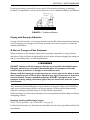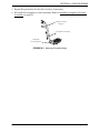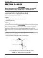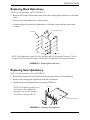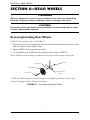
1
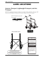
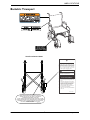
Owner’s Operator and Maintenance Manual
Transport Chairs
Invacare Transport
Lightweight Transport
Bariatric Transport
Lite Transport
DEALER: This manual MUST be given to
the user of this product.
USER: BEFORE using this product, read this
manual and save for future reference.
For more information regarding
Invacare products, parts, and services,
please visit www.invacare.com
WARNING
DO NOT OPERATE THIS EQUIPMENT WITHOUT FIRST READING
AND UNDERSTANDING THIS MANUAL. IF YOU ARE UNABLE TO
UNDERSTAND THE WARNINGS, CAUTIONS, AND
INSTRUCTIONS, CONTACT A HEALTHCARE PROFESSIONAL,
DEALER OR A QUALIFIED TECHNICIAN BEFORE ATTEMPTING
TO USE THIS EQUIPMENT - OTHERWISE INJURY OR DAMAGE
MAY RESULT.
PROCEDURES OTHER THAN THOSE DESCRIBED IN THIS
MANUAL MUST BE PERFORMED BY A QUALIFIED TECHNICIAN.
NOTE: Updated versions of this manual are available on www.invacare.com.
Transport Chairs
2
Part No.1125095
TABLE OF CONTENTS
TABLE OF CONTENTS
REGISTER YOUR PRODUCT ............................................................... 4
SPECIAL NOTES ................................................................................ 5
LABEL LOCATIONS ........................................................................... 6
Invacare Transport, Lightweight Transport, and Lite Transport.....................................................6
Bariatric Transport.....................................................................................................................................7
TYPICAL PRODUCT PARAMETERS .................................................... 8
SECTION 1—GENERAL GUIDELINES ................................................. 10
Operating Information.............................................................................................................................10
Weight Training ........................................................................................................................................11
Weight Limitation.....................................................................................................................................11
SECTION 2—SAFETY/HANDLING ..................................................... 12
Safety/Handling of Transport Chairs....................................................................................................12
Stability and Balance ............................................................................................................................12
Coping with Everyday Obstacles......................................................................................................13
A Note to Transport Chair Assistants ...........................................................................................13
Reaching, Leaning and Bending Forward ..................................................................................13
Reaching, Leaning Backwards ......................................................................................................14
Tipping ....................................................................................................................................................14
Stairways ................................................................................................................................................15
Folding and Unfolding Transport Chair ..........................................................................................16
Unfolding ..........................................................................................................................................16
Folding ...............................................................................................................................................17
SECTION 3—SAFETY INSPECTION ................................................... 18
Safety Inspection Checklists...................................................................................................................18
Inspect/Adjust Initially .........................................................................................................................18
Inspect/Adjust Weekly........................................................................................................................19
Inspect/Adjust Monthly.......................................................................................................................19
Inspect/Adjust Periodically.................................................................................................................19
Troubleshooting .............................................................................................................20
Maintenance ...............................................................................................................................................20
Maintenance Safety Precautions .......................................................................................................20
Suggested Maintenance Procedures ................................................................................................20
SECTION 4—FRONT RIGGINGS ........................................................ 22
Installing Swingaway Footrest Assembly .............................................................................................22
Adjusting Footplate Height.....................................................................................................................22
SECTION 5—BACK ......................................................................... 24
Part No.1125095
3
Transport Chairs
TABLE OF CONTENTS
TABLE OF CONTENTS
Unfolding/Folding the Fold-Down Back...............................................................................................24
Folding ....................................................................................................................................................24
Unfolding................................................................................................................................................24
Replacing Back Upholstery .....................................................................................................................25
Replacing Seat Upholstery......................................................................................................................25
SECTION 6—REAR WHEELS ............................................................. 26
Removing/Installing Rear Wheels .........................................................................................................26
SECTION 7—CASTERS ..................................................................... 27
Replacing/Adjusting Front Forks ...........................................................................................................27
Replacing ................................................................................................................................................27
Adjusting ................................................................................................................................................27
Replacing Front Casters..........................................................................................................................28
SECTION 8—HAND BRAKES/WHEEL LOCKS ...................................... 29
Locking/Unlocking/Using Hand Brakes................................................................................................29
Locking Hand Brake ............................................................................................................................29
Unlocking Hand Brake ........................................................................................................................29
Using Hand Brake ................................................................................................................................30
Adjusting Hand Brakes ............................................................................................................................30
Adjusting Brake Handle ......................................................................................................................30
Adjusting Cable Adjuster Unit ..........................................................................................................31
Adjusting Wheel Lock .............................................................................................................................31
LIMITED WARRANTY ..................................................................... 35
REGISTER YOUR PRODUCT
The benefits of registering include:
1. Safeguarding your investment.
2. Ensuring long-term maintenance and servicing of your product.
3. Receiving updates with product information, maintenance tips and industry news.
Register ONLINE at warranty.invacare.com
Please have your model number and purchase date available to complete your registration.
Any registration information you submit will only be used by Invacare Corporation and
protected as required by applicable laws and regulations.
Transport Chairs
4
Part No.1125095
SPECIAL NOTES
SPECIAL NOTES
Signal words are used in this manual and apply to hazards or unsafe practices which
could result in personal injury or property damage. Refer to the following table for
definitions of the signal words.
SIGNAL WORD
DANGER
MEANING
Danger indicates an imminently hazardous situation which, if not avoided, will result in
death or serious injury.
WARNING
Warning indicates a potentially hazardous situation which, if not avoided, could result in
death or serious injury.
CAUTION
Caution indicates a potentially hazardous situation which, if not avoided, may result in
property damage.
NOTICE
THE INFORMATION CONTAINED IN THIS DOCUMENT IS SUBJECT TO
CHANGE WITHOUT NOTICE.
TRANSPORT CHAIR USER
As a manufacturer of transport chairs, Invacare endeavors to supply a wide variety
of transport chairs to meet many needs of the end user. However, final selection of
the type of transport chair to be used by an individual rests solely with the user and
his/her healthcare professional capable of making such a selection.
TRANSPORT CHAIR TIE-DOWN RESTRAINTS AND SEAT POSITIONING
STRAP
Transport chair users should not be transported in vehicles of any kind while in
transport chairs. As of this date, the Department of Transportation has not
approved any tie-down systems for transportation of a user while in a transport
chair, in a moving vehicle of any type.
It is Invacare’s position that users of transport chairs should be transferred into
appropriate seating in vehicles for transportation and use be made of the seat
positioning strap made available by the auto industry. Invacare cannot and does not
recommend any chair transportation systems.
WARNING
Invacare products are specifically designed and manufactured for use in conjunction
with Invacare accessories. Accessories designed by other manufacturers have not
been tested by Invacare and are not recommended for use with Invacare products.
Part No.1125095
5
Transport Chairs
LABEL LOCATIONS
LABEL LOCATIONS
Invacare Transport, Lightweight Transport, and Lite
Transport
NOTE: The Lightweight transport is shown as an example. Unless indicated on this page, label
locations and wording are the same for the Invacare transport and the Lite transport.
NOTE: This label is only on the
Lite transport.
View From Back of Chair
IMPORTANT NOTICE
The wheel locks on this transport chair have
been pre-set at the factory to comply with the
Veterans Administration functional Standard
8320.01 of the Federal Register, paragraph
3.2.4.5.3. If these wheel locks do not meet
your needs, follow instructions below.
!
CAUTION
Any wheel lock adjustments should embed
wheel lock shoe at least 1/8" into tire when
locked (3/16" on pneumatic tires).
INSTRUCTIONS FOR WHEEL
LOCK ADJUSTMENTS
1.
2.
3.
NO TRANSPORT CHAIR HAS BEEN APPROVED FOR USE AS A
SEATING SURFACE WITHIN A MOTOR VEHICLE. THIS LABEL IS FOR
INFORMATIONAL PURPOSES ONLY. LIABILITY ISSUES WERE NOT
CONSIDERED IN THE ATTACHMENT OF THIS LABEL.
4.
AUCUNE CHAISE ROULANTE N'A ETE APPROUVEE POUR UTILISATION COMME
SIEGE DANS UN VEHICULE MOTORISE. CETTE ETIQUETTE EST POUR INFORMATION
UNIQUEMENT. LES QUESTIONS DE RESPONSABILITE N'ONT PAS ETE PRISES
EN LIGNE DE COMPTE DANS LE CADRE DE L'APPLICATION
DE CETTE ETIQUETTE.
1143180 Rev A - 4/26/06
Transport Chairs
Loosen wheel lock mounting fastener,
which runs through mounting bracket and
frame.
Slide clamp toward rear wheel until wheel
lock shoe is embedded into tire material at
least 1/8" when handle is engaged to the
lock position (3/16" for pneumatic tires).
Tighten mounting fastener to secure
mounting bracket in desired location and
recheck lock shoe embedding.
Inspect for correct locking action BEFORE
actual use.
P/N 1143193 REV A
6
Part No.1125095
LABEL LOCATIONS
Bariatric Transport
View From Back of Chair
IMPORTANT NOTICE
The wheel locks on this transport chair have
been pre-set at the factory to comply with the
Veterans Administration functional Standard
8320.01 of the Federal Register, paragraph
3.2.4.5.3. If these wheel locks do not meet
your needs, follow instructions below.
!
CAUTION
Any wheel lock adjustments should embed
wheel lock shoe at least 1/8" into tire when
locked (3/16" on pneumatic tires).
INSTRUCTIONS FOR WHEEL
LOCK ADJUSTMENTS
1.
2.
3.
4.
Loosen wheel lock mounting fastener,
which runs through mounting bracket and
frame.
Slide clamp toward rear wheel until wheel
lock shoe is embedded into tire material at
least 1/8" when handle is engaged to the
lock position (3/16" for pneumatic tires).
Tighten mounting fastener to secure
mounting bracket in desired location and
recheck lock shoe embedding.
Inspect for correct locking action BEFORE
actual use.
P/N 1143193 REV A
NO TRANSPORT CHAIR HAS BEEN APPROVED FOR USE AS A
SEATING SURFACE WITHIN A MOTOR VEHICLE. THIS LABEL IS FOR
INFORMATIONAL PURPOSES ONLY. LIABILITY ISSUES WERE NOT
CONSIDERED IN THE ATTACHMENT OF THIS LABEL.
AUCUNE CHAISE ROULANTE N'A ETE APPROUVEE POUR UTILISATION COMME
SIEGE DANS UN VEHICULE MOTORISE. CETTE ETIQUETTE EST POUR INFORMATION
UNIQUEMENT. LES QUESTIONS DE RESPONSABILITE N'ONT PAS ETE PRISES
EN LIGNE DE COMPTE DANS LE CADRE DE L'APPLICATION
DE CETTE ETIQUETTE.
1143180 Rev A - 4/26/06
Part No.1125095
7
Transport Chairs
TYPICAL PRODUCT PARAMETERS
TYPICAL PRODUCT PARAMETERS
INVACARE TRANSPORT
SEAT WIDTH (BETWEEN ARMS)
17,18,19 and 20 inches
SEAT DEPTH
16 inches
OVERALL WIDTH
17½ to 22½ inches
OVERALL DEPTH (WITHOUT RIGGINGS)
23 inches
SEAT-TO-FLOOR
19½ inches
BACK STYLE
Fold-down
BACK HEIGHT
18 inches
ARM STYLES
Permanent
FRONT RIGGINGS
Swingaway footrest
REAR AXLE
Permanent
REAR WHEELS
8 X 1 inch
WHEEL LOCKS
Push to lock
CASTER SIZE
8 X 1 inch (Standard)
UPHOLSTERY
Black Nylon
WEIGHT (APPROXIMATE)
26 lbs (without front riggings)
SHIPPING WEIGHT (APPROXIMATE)
30 lbs (without front riggings)
WEIGHT LIMITATION
250 lbs
LIGHTWEIGHT TRANSPORT
SEAT WIDTH (BETWEEN ARMS)
19 inches and 17 inches
SEAT DEPTH
15¼ inches
OVERALL WIDTH
23½ inches
OVERALL DEPTH (WITHOUT RIGGINGS)
23½ inches and 21½ inches
SEAT-TO-FLOOR
19¼ inches
BACK STYLE
Fold-down
BACK HEIGHT
17½ inches
ARM STYLES
Permanent
FRONT RIGGINGS
Swingaway footrest
REAR AXLE
Permanent
REAR WHEELS
8 X 1 inch
WHEEL LOCKS
Push to lock
CASTER SIZE
8 X 1 inch (Standard)
UPHOLSTERY
Black Nylon
WEIGHT (APPROXIMATE)
19 lbs (without front riggings)
SHIPPING WEIGHT (APPROXIMATE)
26 lbs (without front riggings)
WEIGHT LIMITATION
250 lbs
Transport Chairs
8
Part No.1125095
TYPICAL PRODUCT PARAMETERS
BARIATRIC TRANSPORT
SEAT WIDTH (BETWEEN ARMS)
22 inches
SEAT DEPTH
18 inches
OVERALL WIDTH
28 inches
OVERALL DEPTH (WITHOUT RIGGINGS)
28½ inches
SEAT-TO-FLOOR
19½ inches
BACK STYLE
Fold-down
BACK HEIGHT
18 inches
ARM STYLES
Removable
FRONT RIGGINGS
Swingaway footrest
REAR AXLE
Permanent
REAR WHEELS
12½ X 2¼ inch
WHEEL LOCKS
Push to lock
HAND BRAKES
Push down to lock, pull up to stop
CASTER SIZE
8 X 1 inch (Standard)
UPHOLSTERY
Black Nylon
WEIGHT (APPROXIMATE)
41 lbs (without front riggings)
SHIPPING WEIGHT (APPROXIMATE)
45 lbs (without front riggings)
WEIGHT LIMITATION
400 lbs
LITE TRANSPORT
SEAT WIDTH (BETWEEN ARMS)
19 inches
SEAT DEPTH
18 inches
OVERALL WIDTH
23½ inches
OVERALL DEPTH (WITHOUT RIGGINGS)
24½ inches
SEAT-TO-FLOOR
19¼ inches
BACK STYLE
Fold-down
BACK HEIGHT
17½ inches
ARM STYLES
Permanent
FRONT RIGGINGS
Swingaway footrest
REAR AXLE
Permanent
REAR WHEELS
12 X 1¾ inch
WHEEL LOCKS
Push to lock
HAND BRAKES
Push down to lock, pull up to stop
CASTER SIZE
8 X 1 inch (Standard)
UPHOLSTERY
Black Nylon
WEIGHT (APPROXIMATE)
19 lbs (without front riggings)
SHIPPING WEIGHT (APPROXIMATE)
26 lbs (without front riggings)
WEIGHT LIMITATION
250 lbs
Part No.1125095
9
Transport Chairs
SECTION 1—GENERAL GUIDELINES
SECTION 1—GENERAL GUIDELINES
WARNING
SECTION 1 - GENERAL GUIDELINES contains important information for the safe
operation and use of this product. DO NOT use this product or any available
optional equipment without first completely reading and understanding these
instructions and any additional instructional material such as Owner’s Manuals,
Service Manuals or Instruction Sheets supplied with this product or optional
equipment. If you are unable to understand the Warnings, Cautions or Instructions,
contact a healthcare professional, dealer or technical personnel before attempting
to use this equipment - otherwise, injury or damage may occur.
Operating Information
To determine and establish your particular safety limits, practice bending, reaching and
transferring activities in several combinations in the presence of a qualified health
professional before attempting active use of the transport chair.
Make sure the back is locked securely before using this transport chair.
ALWAYS check hand grips for looseness before using the transport chair. If loose and/or
worn, replace immediately.
If transport chair is exposed to extreme temperature (above 100°F or below 32°F), high
humidity and/or becomes wet, prior to use, ensure handgrips DO NOT twist on the
transport chair handle - otherwise damage or injury may occur.
DO NOT attempt to reach objects if you have to move forward in the seat.
DO NOT attempt to reach objects if you have to pick them up from the floor by reaching
down between your knees.
DO NOT lean over the top of the back upholstery to reach objects behind you, as this may
cause the transport chair to tip over.
DO NOT shift your weight or sitting position toward the direction you are reaching as the
transport chair may tip over.
DO NOT tilt the transport chair without assistance.
DO NOT use an escalator to move a transport chair between floors. Serious bodily injury
may occur.
NEVER leave an unoccupied transport chair on an incline.
DO NOT attempt to stop a moving transport chair with wheel locks. Wheel locks are not
brakes.
Invacare recommends that a non-folding device be installed to keep the transport chair
from being folded when left unoccupied in a public place.
Transport Chairs
10
Part No.1125095
SECTION 1—GENERAL GUIDELINES
Before attempting to transfer in or out of the transport chair, every precaution should be
taken to reduce the gap distance. Turn both casters parallel to the object you are
transferring onto. When transferring to and from the transport chair, ALWAYS engage
both wheel locks. If the transport chair is equipped with hand brakes, ALWAYS lock both
hand brakes before transferring to and from the transport chair.
DO NOT sit or transfer into the transport chair unless it is fully open.
DO NOT operate on roads, streets or highways.
DO NOT climb, go up or down ramps or traverse slopes greater than 9 degrees.
DO NOT attempt to move up or down an incline with a water, ice or oil film.
DO NOT attempt to ride over curbs or obstacles. Doing so may cause your transport chair
to tip over and cause bodily harm or damage to the transport chair.
Invacare products are specifically designed and manufactured for use in conjunction with
Invacare accessories. Accessories designed by other manufacturers have not been tested
by Invacare and are not recommended for use with Invacare products.
DO NOT overtighten hardware attaching to the frame. This could cause damage to the
frame tubing.
ALWAYS keep hands and fingers clear of moving parts to avoid injury.
DO NOT stand on the footplates. When getting in or out of the transport chair, make sure
that the footplates are in the upward position or swing the footrest towards the outside
of the transport chair.
DO NOT attempt to lift the transport chair by any removable (detachable) parts. Lifting
by means of any removable (detachable) parts of a transport chair may result in injury to
the user or damage to the transport chair.
DO NOT stand on the frame of the transport chair.
Weight Training
Invacare does not recommend the use of its transport chairs as a weight training
apparatus. Invacare transport chairs have not been designed or tested as a seat for any
kind of weight training. If occupant uses said transport chair as a weight training
apparatus, Invacare shall not be liable for bodily injury and the warranty will be void.
Weight Limitation
The following are the weight limitations for the Invacare transport chairs:
Part No.1125095
TRANSPORT CHAIR
WEIGHT LIMITATION (LBS)
Transport
250
Lightweight Transport
250
Bariatric Transport
400
Lite Transport
250
11
Transport Chairs
SECTION 2—SAFETY/HANDLING
SECTION 2—SAFETY/HANDLING
Safety/Handling of Transport Chairs
Safety and handling of the transport chair requires the close attention of the transport
chair user as well as the assistant. This manual points out the most common procedures
and techniques involved in the safe operation and maintenance of the transport chair. It
is important to practice and master these safe techniques until you are comfortable in
maneuvering around the frequently encountered architectural barriers.
Use this information only as a basic guide. The techniques that are discussed on the
following pages have been used successfully by many.
Individual transport chair users often develop skills to deal with daily living activities
that may differ from those described in this manual. Invacare recognizes and encourages
each individual to try what works best for him/her in overcoming architectural obstacles
that they may encounter. However, all warnings and cautions given in this manual MUST
be followed. Techniques in this manual are a starting point for the new transport chair
user and assistant with safety as the most important consideration for all.
Stability and Balance
NOTE: For this procedure, refer to FIGURE 2.1 on page 13.
To assure stability and proper operation of your transport chair, you must at all times
maintain proper balance. Your transport chair has been designed to remain upright and
stable during normal daily activities as long as you do not move beyond the center of
gravity.
Virtually all activities which involve movement in the transport chair have an effect on
the center of gravity. Invacare recommends using seat/chest positioning straps for
additional safety while involved in activities that shift your weight.
DO NOT lean forward out of the transport chair any further than the length of the
armrests. Make sure the casters are pointing in the forward position whenever you lean
forward. This can be achieved by advancing the transport chair and then reversing it in a
straight line.
WARNING
DO NOT attempt to reach objects if you have to move forward in the seat or pick
them up from the floor by reaching down between your knees.
Many activities require the transport chair owner to reach, bend and transfer in and out
of the transport chair. These movements will cause a change to the normal balance, the
center of gravity, and the weight distribution of the transport chair. To determine and
establish your particular safety limits, practice bending, reaching and transferring
activities in several combinations in the presence of a qualified healthcare professional
before attempting active use of the transport chair.
Transport Chairs
12
Part No.1125095
SECTION 2—SAFETY/HANDLING
Proper positioning is essential for your safety. When reaching, leaning, or bending
forward, it is important to use the front casters as a tool to maintain stability and balance.
Center of
Gravity
FIGURE 2.1 Stability and Balance
Coping with Everyday Obstacles
Coping with the irritation of everyday obstacles can be alleviated somewhat by learning
how to manage your transport chair. Keep in mind your center of gravity to maintain
stability and balance.
A Note to Transport Chair Assistants
When assistance to the transport chair user is required, remember to use good body
mechanics. Keep your back straight and bend your knees whenever tipping the transport
chair or traversing curbs, or other impediments.
WARNING
DO NOT attempt to lift the transport chair by any removable (detachable) parts.
Lifting by means of any removable (detachable) parts of a transport chair may
result in injury to the user or damage to the transport chair.
Always verify that hand grips on the rear cane are secure prior to use when an assistant is used to propel or lift the chair. Check for any signs of looseness or deterioration and if found, contact a qualified technician. DO NOT attempt to move the
transport chair by pulling on the hand grips if they are found to be unsecure or have
deteriorated.
Also, be aware of detachable parts such as armrests or legrests. These must NEVER be
used to move the transport chair or as lifting supports, as they may be inadvertently
released, resulting in possible injury to the user and/or assistant(s).
When learning a new assistance technique, have an experienced assistant help you before
attempting it alone.
Reaching, Leaning and Bending Forward
NOTE: For this procedure, refer to FIGURE 2.2 on page 14.
Position the front casters so that they are extended as far forward as possible and lock the
hand brakes.
Part No.1125095
13
Transport Chairs
SECTION 2—SAFETY/HANDLING
WARNING
DO NOT attempt to reach objects if you have to move forward in the seat or pick
them up from the floor by reaching down between your knees.
FIGURE 2.2 Reaching, Leaning and Bending Forward
Reaching, Leaning Backwards
WARNING
DO NOT lean over the top of the back upholstery. This will change your center of
gravity and may cause you to tip over.
NOTE: For this procedure, refer to
FIGURE 2.3.
Position transport chair as close as possible
to the desired object. Point front casters
forward to create the longest possible
wheelbase. Reach back only as far as your
arm will extend without changing your
sitting position.
FIGURE 2.3 Reaching, Leaning Backwards
Tipping
WARNING
DO NOT tip the transport chair without assistance.
NOTE: For this procedure, refer to FIGURE 2.4 on page 15.
When tipping the transport chair, an assistant should grasp the back of the transport chair
on a non-removable (non-detachable) part. Inform the transport chair occupant before
tipping the transport chair and remind him/her to lean back. Be sure the occupant’s feet
and hands are clear of all wheels and/or pinch points.
Transport Chairs
14
Part No.1125095
SECTION 2—SAFETY/HANDLING
After mastering the techniques of tipping the transport chair, use the following method
to tackle curbs, short stairs, etc.
Place a foot on the step tube and begin to tilt the transport chair toward you. Apply a
continuous downward motion until the balance point is achieved and the front casters
clear the curb. At this point, the assistant will feel a difference in the weight distribution.
WARNING
When lowering the front casters of the transport chair, DO NOT let the transport
chair drop the last few inches to the ground. This could result in injury to the occupant and/or damage to the transport chair.
Roll the transport chair forward and slowly lower the front of the transport chair in one
continuous movement onto the sidewalk. Push the transport chair forward until the rear
wheels roll up and over the curb.
Step Tube
FIGURE 2.4 Tipping
Stairways
WARNING
DO NOT attempt to lift a transport chair by lifting on any removable (detachable)
parts. Lifting by means of any removable (detachable) parts of a transport chair may
result in injury to the user or damage to the transport chair.
Always verify that hand grips on the rear cane are secure prior to use when an
assistant is used to propel or lift the chair. Check for any signs of looseness or
deterioration and if found, contact a qualified technician. DO NOT attempt to
move the transport chair by pulling on the hand grips if they are found to be
unsecure or have deteriorated.
Extreme caution is advised when it is necessary to move an occupied transport
chair up or down the stairs. Invacare recommends that, if possible, the user be
removed from the transport chair prior to moving. Invacare recommends using two
assistants and making thorough preparations. Make sure to use only secure,
non-detachable parts for hand-held supports.
Part No.1125095
15
Transport Chairs
SECTION 2—SAFETY/HANDLING
Follow this procedure for moving the transport chair between floors when an elevator is
NOT available:
1. After the transport chair has been tilted back to the balance point, one assistant (in the
rear) backs the transport chair up against the first step, while securely grasping a
non-removable (non-detachable) part of the transport chair for leverage.
2. The second assistant, with a firm hold on a non-detachable part of the framework, lifts
the transport chair up and over the stair and steadies the transport chair as the first
assistant places one foot on the next stair and repeats STEP 1.
3. The transport chair should not be lowered until the last stair has been negotiated and
the transport chair has been rolled away from the stairway.
WARNING
DO NOT use an escalator to move a transport chair between floors. Serious bodily
injury may occur.
Folding and Unfolding Transport Chair
Unfolding
NOTE: For this procedure, refer to FIGURE 2.5.
1. Open the transport chair by grasping the push handle of the transport chair closest to
you.
2. Tilt the transport chair toward you (raising the opposite wheel and caster off the
ground/floor).
3. Push downward on the top of the seat rail closest to you where the seat upholstery is
attached until the transport chair is fully open.
FIGURE 2.5 Unfolding
Transport Chairs
16
Part No.1125095
SECTION 2—SAFETY/HANDLING
Folding
WARNING
ALWAYS use the straps on the seat rails when folding the transport chair.
Otherwise, hands and fingers may become pinched between the seat rail and the
armrest and injury may occur.
NOTE: For this procedure, refer to FIGURE 2.6.
1. Swing the footrest/legrest in locked position to the front of the transport chair.
2. Pivot the footplates upward to vertical position.
3. Grasp the two straps on the seat rails and pull up to begin closing the transport chair.
4. Continue to close the transport chair by grasping the armrest furthest from you and
pulling the armrest toward you.
FIGURE 2.6 Folding
Part No.1125095
17
Transport Chairs
SECTION 3—SAFETY INSPECTION
SECTION 3—SAFETY INSPECTION
NOTE: Every six months take your transport chair to a qualified technician for a thorough
inspection and servicing. Regular cleaning will reveal loose or worn parts and enhance the smooth
operation of your transport chair. To operate properly and safely, your transport chair must be
cared for just like any other vehicle. Routine maintenance will extend the life and efficiency of your
transport chair.
Safety Inspection Checklists
Initial adjustments should be made to suit your personal body structure and
preference. Thereafter follow these maintenance procedures:
Inspect/Adjust Initially
❑ Ensure transport chair rolls straight (no excessive drag or pull to one side).
❑ Inspect seat and back upholstery for rips or sagging.
❑ Inspect back cane hand grips for wear, looseness, and/or deterioration.
❑ Inspect for any loose or broken hardware on the transport chair.
❑ Ensure that there is no excessive side movement or binding when the rear wheels are
lifted and spun.
❑ Inspect for cracked, broken or loose spokes.
❑ Ensure the wheel/fork assembly has proper tension when the caster is spun. The caster
should come to a gradual stop.
❑ Loosen/tighten the locknut if the wheel wobbles noticeably or binds to a stop.
❑ Ensure the wheel bearings are clean and free of moisture.
CAUTION
As with any vehicle, wheels and tires should be checked periodically for cracks and
wear and should be replaced as necessary.
❑ Inspect the tires for flat spots and wear.
❑ Ensure the hand brakes DO NOT interfere with the tires when rolling.
❑ Ensure the hand brake pivot points are free of wear and looseness.
❑ Ensure the hand brakes are easy to engage.
❑ Clean upholstery and armrests.
Transport Chairs
18
Part No.1125095
SECTION 3—SAFETY INSPECTION
Inspect/Adjust Weekly
❑ Ensure the transport chair rolls straight (no excessive drag or pull to one side).
❑ Inspect for cracked, broken or loose spokes.
❑ Ensure the wheel/fork assembly has proper tension when caster is spun. The caster
should come to a gradual stop.
❑ Ensure the hand brakes do not interfere with tires when rolling.
❑ Ensure the hand brake pivot points are free of wear and looseness.
Inspect/Adjust Monthly
❑ Inspect for any loose or broken hardware on the transport chair.
❑ Inspect back cane hand grips for wear, looseness, and/or deterioration.
❑ Loosen/tighten the locknut if the wheel wobbles noticeably or binds to a stop.
❑ Ensure the wheel bearings are clean and free of moisture.
CAUTION
As with any vehicle, the wheels and tires should be checked periodically for cracks
and wear and should be replaced as necessary.
❑ Ensure the hand brakes do not interfere with the tires when rolling.
Inspect/Adjust Periodically
❑ Ensure the transport chair rolls straight (no excessive drag or pull to one side).
❑ Inspect the seat and the back upholstery for rips or sagging.
❑ Ensure that there is no excessive side movement or binding when the rear wheels are
lifted and spun.
❑ Ensure the wheel bearings are clean and free of moisture.
CAUTION
As with any vehicle, the wheels and tires should be checked periodically for cracks
and wear and should be replaced as necessary.
❑ Ensure that casters are free of debris.
❑ Inspect the tires for flat spots and wear.
❑ Ensure the hand brakes are easy to engage.
❑ Clean the upholstery and armrests.
❑ Check that all labels are present and legible. Replace if necessary.
Part No.1125095
19
Transport Chairs
SECTION 3—SAFETY INSPECTION
Troubleshooting
Chair
Veers
Left/Right
Sluggish Turn
or Performance
X
X
X
Casters
Flutter
Squeaks
and
Rattles
X
Looseness
in
Chair
X
X
Chair 3
Wheels
Solutions
Check for loose
fork stem nuts
and bolts.
Check that both
casters contact
the ground at the
same time.
X
Maintenance
Maintenance Safety Precautions
WARNING
After ANY adjustments, repair or service and BEFORE use, make sure all attaching
hardware is tightened securely. Otherwise, injury or damage can result.
CAUTION
DO NOT overtighten the hardware attaching to the frame. This could cause damage to the frame tubing.
Suggested Maintenance Procedures
1. Before using your transport chair, do the following:
A. Make sure all the nuts and bolts are tight.
B. Check all the parts for damage or wear and replace.
C. Check all parts for proper adjustment.
2. Periodically check the wheels and tires for cracks and wear. Have a qualified
technician replace if damaged.
3. Periodically adjust the wheel locks in correlation to tire wear. Refer to Adjusting
Wheel Lock on page 31.
4. Periodically check the front caster and the rear wheel hubs to make sure they are clean
and free of cracks.
Transport Chairs
20
Part No.1125095
SECTION 3—SAFETY INSPECTION
WARNING
When cleaning the rear cane or hand grip areas, use only a clean towel lightly dampened with cool water. Verify that grips are dry prior to use. The use of soap or
ammonia based cleaning solutions will result in the hand grips sliding off the cane
assembly. Failure to observe this warning could result in injury to the user or
bystanders.
5. Hand grips should be checked monthly for wear/looseness. Clean if desired.
6. Check the upholstery for sagging, rips or tears.
Part No.1125095
21
Transport Chairs
SECTION 4—FRONT RIGGINGS
SECTION 4—FRONT RIGGINGS
WARNING
After any adjustments, repair or service and before use, make sure all attaching
hardware is tightened securely. Otherwise, injury or damage may result.
Installing Swingaway Footrest Assembly
NOTE: For this procedure, refer to FIGURE 4.1.
1. Turn the footrest to the side (open footplate is perpendicular to transport chair).
2. Install the hinge plates on the footrest onto the hinge pins on the transport chair frame.
3. Push the footrest towards the inside of the transport chair until it locks into place.
NOTE: The footplate will be on the inside of the transport chair when locked in place.
4. Repeat this procedure for the other footrest assembly.
5. To release the footrest, push the footrest release lever inward, rotate the footrest
outward.
Footrest Release Lever
Hinge Pins
Hinge
Plates
Swingaway Footrest
Assembly
FIGURE 4.1 Installing Swingaway Footrest Assembly
Adjusting Footplate Height
NOTE: For this procedure, refer to FIGURE 4.2 on page 23.
1. Remove the swingaway footrest assembly. Refer to Installing Swingaway Footrest
Assembly on page 22.
NOTE: Lay the assembly on a flat surface to simplify this procedure.
2. Loosen, but DO NOT remove, the footplate mounting bolt until the footplate assembly
moves freely.
3. Reposition the footplate assembly to the desired height.
4. Securely tighten the footplate mounting bolt.
Transport Chairs
22
Part No.1125095
SECTION 4—FRONT RIGGINGS
5. Repeat this procedure for the other footrest, if necessary.
6. Reinstall the swingaway footrest assembly. Refer to Installing Swingaway Footrest
Assembly on page 22.
Upper Footrest
Support
Footplate Assembly
Footplate
Mounting Bolt
FIGURE 4.2 Adjusting Footplate Height
Part No.1125095
23
Transport Chairs
SECTION 5—BACK
SECTION 5—BACK
WARNING
After any adjustments, repair or service and before use, make sure all attaching
hardware is tightened securely. Otherwise, injury or damage could result.
Unfolding/Folding the Fold-Down Back
NOTE: For this procedure, refer to FIGURE 5.1.
Folding
1. Disengage the release mechanism on the back canes.
2. Pull the handles down.
Unfolding
WARNING
When unfolding the back, ensure all occupant's and/or assistant’s body parts are
away from the folding mechanism. Otherwise, pinching and injury may occur.
Make sure the release levers are securely locked in place before using the transport
chair.
1. Pull up on the two back canes until the release mechanisms lock in place.
NOTE: There will be an audible click.
2. Pull on the handles to make sure the back is locked in place.
Back Cane
Handle
Release Mechanism
NOTE: Handle shown for the Transport and the Lightweight Transport.
FIGURE 5.1 Unfolding/Folding the Fold-Down Back
Transport Chairs
24
Part No.1125095
SECTION 5—BACK
Replacing Back Upholstery
NOTE: For this procedure, refer to FIGURE 5.2.
1. Remove the screws and washers that secure the existing back upholstery to the back
canes.
2. Position new back upholstery on back canes.
3. Securely tighten the new back upholstery to the back canes with the screws and
washers.
Back Upholstery
Washer
Screws
Washer
NOTE: Back upholstery shown is for the Transport and the Lightweight Transport. The Lite
Transport has 10 screws and washers. The Bariatric Transport has 16 screws and washers.
FIGURE 5.2 Replacing Back Upholstery
Replacing Seat Upholstery
NOTE: For this procedure, refer to FIGURE 5.3.
1. Remove the screws that secure the existing seat upholstery to the crossbraces.
2. Remove the existing seat upholstery from the crossbraces.
3. Install the new seat upholstery by reversing STEPS 1-2.
Screws
NOTE: Seat upholstery shown is for
the Transport, the Lightweight
Transport, and the Lite Transport.
The Bariatric Transport has 14
Seat Upholstery
FIGURE 5.3 Replacing Seat Upholstery
Part No.1125095
25
Transport Chairs
SECTION 6—REAR WHEELS
SECTION 6—REAR WHEELS
WARNING
After any adjustments, repair or service and before use, make sure all attaching
hardware is tightened securely. Otherwise, injury or damage could result.
CAUTION
As with any vehicle, the wheels and tires should be checked periodically for cracks
and wear, and should be replaced.
Removing/Installing Rear Wheels
NOTE: For this procedure, refer to FIGURE 6.1.
1. Remove the dust cap (if applicable), hex screw and locknut that secure the rear wheel
and axle spacer to the transport chair.
2. Repeat STEP 1 for the opposite rear wheel.
3. To reinstall the rear wheels onto the transport chair, reverse STEPS 1-2.
NOTE: Make sure the axle spacer is between the rear wheel and the transport chair frame.
Locknut
Axle Spacer
Rear Wheel
Axle Mounting
Hole
Hex Screw
NOTE: Rear wheel shown for Invacare Transport and Lightweight Transport. Dust cap for
Bariatric Transport and Lite Transport not shown.
FIGURE 6.1 Removing/Installing Rear Wheels
Transport Chairs
26
Part No.1125095
SECTION 7—CASTERS
SECTION 7—CASTERS
WARNING
After any adjustments, repair or service and before use, make sure all attaching
hardware is tightened securely - otherwise injury or damage may result.
CAUTION
As with any vehicle, the wheels and tires should be checked periodically for cracks
and wear, and should be replaced when necessary.
Replacing/Adjusting Front Forks
NOTE: For this procedure, refer to FIGURE 7.1 on page 28.
Replacing
1. Remove the caster from the fork. Refer to Replacing Front Casters on page 28.
2. Remove the dust cover.
3. Remove the locknut and nylon washer that secure the fork to the caster headtube.
4. Drop the fork out of the caster headtube.
5. Slide the new fork into the caster headtube and reassemble by reversing STEPS 1-4.
6. Adjust the forks. Refer to Adjusting on page 27.
7. Repeat STEPS 1-6 for the opposite fork, if necessary.
Adjusting
1. Remove the dust cover.
2. To properly tighten the caster journal system and guard against flutter, perform the
following check:
A. Tip back the transport chair to floor.
B. Simultaneously pivot both forks and casters to the top of their arc.
C. Let the casters drop to the bottom of the arc (wheels should swing once to one-side,
then immediately rest in a straight downward position).
D. Adjust the locknuts according to freedom of the caster swing.
3. Test the transport chair for maneuverability.
4. Readjust the locknuts if necessary, and repeat STEPS 2-3 until correct.
5. Snap the dust cover over the locknut and stem.
Part No.1125095
27
Transport Chairs
SECTION 7—CASTERS
Dust Cover
Locknut
Nylon Washer
Caster Headtube
Front Caster
and Fork
FIGURE 7.1 Replacing/Adjusting Front Forks
Replacing Front Casters
NOTE: For this procedure, refer to FIGURE 7.2.
1. Remove the hex screw, washers and locknut that secure the front caster to the fork.
2. Install the new front caster onto the transport chair by reversing STEP 1.
3. Repeat STEPS 1-2 for the opposite front caster if necessary.
Fork
Locknut
Hex Screw
Front Caster
NOTE: Dust cap not shown.
FIGURE 7.2 Replacing Front Casters
Transport Chairs
28
Part No.1125095
SECTION 8—HAND BRAKES/WHEEL LOCKS
SECTION 8—HAND BRAKES/WHEEL
LOCKS
WARNING
After any adjustments, repair or service and before use, make sure all attaching
hardware is tightened securely. Otherwise, injury or damage may result.
DO NOT leave the Bariatric Transport on inclined surfaces. The wheel locks and
hand brakes may not hold the Bariatric Transport on inclined surfaces due to the
transport chair’s increased weight capacity.
Wheel locks are not brakes. DO NOT attempt to stop a moving transport chair
with the wheel locks.
Before attempting to transfer in or out of the transport chair, every precaution
should be taken to reduce the gap distance. Turn both casters parallel to the object
you are transferring onto. When transferring to and from the transport chair,
ALWAYS engage both wheel locks. If the transport chair is equipped with hand
brakes, ALWAYS lock both hand brakes before transferring to and from the transport chair.
Locking/Unlocking/Using Hand Brakes
NOTE: These procedures are applicable only to the Bariatric Transport and the Lite Transport.
Locking Hand Brake
NOTE: For this procedure, refer to
FIGURE 8.1.
1. Push down on the bottom portion of
the brake handle until an audible click
is heard.
2. Refer to Unlocking Hand Brake on
page 29.
FIGURE 8.1 Locking Hand Brake
Unlocking Hand Brake
NOTE: For this procedure, refer to
FIGURE 8.2.
1. Pull up on the top portion of the brake
handle to release.
2. Release the brake handle.
FIGURE 8.2 Unlocking Hand Brake - Using
Hand Brake
Part No.1125095
29
Transport Chairs
SECTION 8—HAND BRAKES/WHEEL LOCKS
Using Hand Brake
NOTE: For this procedure, refer to FIGURE 8.2 on page 29.
1. Pull up on the top portion of the brake handles toward the push handles.
2. Do one of the following:
• Remain stationary - Hold the brake handle up.
• Continue mobility - Release the brake handle.
Adjusting Hand Brakes
NOTE: This procedure is applicable only to the Bariatric Transport and the Lite Transport.
NOTE: Counterclockwise/clockwise directions are determined by standing behind the transport
chair (user’s position).
Adjusting Brake Handle
NOTE: For this procedure, refer to FIGURE 8.3.
Test the brake handle. Observe how the brake lever engages the wheel. If the tension of
the brake is too loose or too tight, adjust using the following steps:
1. Loosen the brake handle adjustment nut by turning clockwise.
2. Perform one of the following:
• Loosen brake handle tension - Turn the brake handle nut clockwise.
NOTE: If the brake lever is scraping the rear wheel, the brake handle must be loosened.
• Tighten brake handle tension - Turn the brake handle nut counterclockwise.
NOTE: If the brake lever does not respond quickly, tighten brakes.
3. Turn the brake handle adjustment nut counterclockwise to secure in place.
4. Do one of the following:
• Acceptable tension - Repeat STEPS 1 - 3 for the opposite side, if necessary.
• Unacceptable tension - Refer to Adjusting Cable Adjuster Unit on page 31.
Brake Handle
Nut
Brake Handle
Adjustment Nut
Brake Cable
FIGURE 8.3 Adjusting Brake Handle
Transport Chairs
30
Part No.1125095
SECTION 8—HAND BRAKES/WHEEL LOCKS
Adjusting Cable Adjuster Unit
NOTE: For this procedure, refer to FIGURE 8.4.
Test the brake with the brake handle. Observe how the brake lever engages the wheel. If
the tension of the brake handle is still too loose or too tight, adjust using the following
steps:
1. Ensure brake handle is not locked.
2. Do one of the following:
• To Loosen: Brace the jam nut while turning the adjustment screw clockwise.
• To Tighten: Brace the jam nut while turning the adjustment screw
counterclockwise.
3. Repeat with other brake.
Adjustment Screw
Brake
Lever
Jam Nut
FIGURE 8.4 Adjusting Cable Adjuster Unit
Adjusting Wheel Lock
NOTE: For this procedure, refer to FIGURE 8.5 on page 32.
1. Loosen the bolt and locknut that secure the wheel lock assembly to the transport chair
frame.
2. Adjust the position of wheel lock until the measurement between the rear wheel and
the wheel lock shoe is between 5/32 and 5/16-inches.
3. Securely tighten the bolt and locknut.
4. Engage the wheel lock.
5. Push against the transport chair and determine if the wheel lock engages the wheel
lock shoe enough to hold the transport chair.
6. Repeat the above procedures until the wheel lock holds the transport chair.
7. Repeat STEPS 1-6 for the opposite wheel lock.
Part No.1125095
31
Transport Chairs
SECTION 8—HAND BRAKES/WHEEL LOCKS
Unlocked Position
Locked Position
Wheel Lock Handle
Wheel Lock Shoe
Bolt and Locknut
5/32 and 5/16 inches
Rear Wheel
Front of
Transport Chair
NOTE: Lightweight Transport
wheel lock shown.
FIGURE 8.5 Adjusting Wheel Lock
Transport Chairs
32
Part No.1125095
NOTES
NOTES
Part No.1125095
33
Transport Chairs
NOTES
NOTES
Transport Chairs
34
Part No.1125095
LIMITED WARRANTY
LIMITED WARRANTY
PLEASE NOTE: THE WARRANTY BELOW HAS BEEN DRAFTED TO COMPLY WITH
FEDERAL LAW APPLICABLE TO PRODUCTS MANUFACTURED AFTER JULY 4, 1975.
This warranty is extended only to the original purchaser who purchases this product when new
and unused from Invacare or a dealer. This warranty is not extended to any other person or
entity and is not transferable or assignable to any subsequent purchaser or owner. Coverage
under this warranty will end upon any such subsequent sale or other transfer of title to any
other person.
This warranty gives you specific legal rights and you may also have other legal rights which vary
from state to state.
Invacare warrants the side frames and cross members of this product when purchased new and
unused to be free from defects in materials and workmanship for a period of thirteen (13)
months from the date of purchase from Invacare or a dealer, with a copy of the seller’s invoice
required for coverage under this warranty. Invacare warrants the upholstered materials (seat,
back and armrests of the arm assembly) and remaining components of this product when
purchased new and unused to be free from defects in materials and workmanship for a period of
thirteen (13) months from date of purchase from Invacare or a dealer, with a copy of the
seller’s invoice required for coverage under this warranty. If within such warranty periods any
such product shall be proven to be defective, such product shall be repaired or replaced, at
Invacare’s option. This warranty does not include any labor or shipping charges incurred in
replacement part installation or repair of any such product. Invacare’s sole obligation and your
exclusive remedy under this warranty shall be limited to such repair and/or replacement.
For warranty service, please contact the dealer from whom you purchased your Invacare
product. In the event you do not receive satisfactory warranty service, please write directly to
Invacare at the address at the bottom of this page. Provide dealer’s name, address, the product
model number, date of purchase, indicate nature of the defect and, if the product is serialized,
indicate the serial number. Do not return products to our factory without our prior consent.
LIMITATIONS AND EXCLUSIONS: THE FOREGOING WARRANTY SHALL NOT APPLY
TO SERIAL NUMBERED PRODUCTS IF THE SERIAL NUMBER HAS BEEN REMOVED OR
DEFACED, PRODUCTS SUBJECTED TO NEGLIGENCE, ACCIDENT, IMPROPER
OPERATION, MAINTENANCE OR STORAGE, PRODUCTS MODIFIED WITHOUT
INVACARE’S EXPRESS WRITTEN CONSENT INCLUDING, BUT NOT LIMITED TO,
MODIFICATION THROUGH THE USE OF UNAUTHORIZED PARTS OR ATTACHMENTS;
PRODUCTS DAMAGED BY REASON OF REPAIRS MADE TO ANY COMPONENT
WITHOUT THE SPECIFIC CONSENT OF INVACARE, OR TO A PRODUCT DAMAGED BY
CIRCUMSTANCES BEYOND INVACARE’S CONTROL, AND SUCH EVALUATION WILL
BE SOLELY DETERMINED BY INVACARE. THE WARRANTY SHALL NOT APPLY TO
NORMAL WEAR AND TEAR OR FAILURE TO ADHERE TO THE PRODUCT
INSTRUCTIONS.
THE FOREGOING EXPRESS WARRANTY IS EXCLUSIVE AND IN LIEU OF ANY OTHER
WARRANTIES WHATSOEVER, WHETHER EXPRESS OR IMPLIED, INCLUDING THE
IMPLIED WARRANTIES OF MERCHANTABILITY AND FITNESS FOR A PARTICULAR
PURPOSE, AND THE SOLE REMEDY FOR VIOLATIONS OF ANY WARRANTY
WHATSOEVER, SHALL BE LIMITED TO REPAIR OR REPLACEMENT OF THE DEFECTIVE
PRODUCT PURSUANT TO THE TERMS CONTAINED HEREIN. THE APPLICATION OF
ANY IMPLIED WARRANTY WHATSOEVER SHALL NOT EXTEND BEYOND THE
DURATION OF THE EXPRESS WARRANTY PROVIDED HEREIN. INVACARE SHALL NOT
BE LIABLE FOR ANY CONSEQUENTIAL OR INCIDENTAL DAMAGES WHATSOEVER.
SOME STATES DO NOT ALLOW THE EXCLUSION OR LIMITATION OF INCIDENTAL OR
CONSEQUENTIAL DAMAGE, OR LIMITATION OF HOW LONG AN IMPLIED WARRANTY
LASTS, SO THE ABOVE EXCLUSION AND LIMITATION MAY NOT BE APPLICABLE.
THIS WARRANTY SHALL BE EXTENDED TO COMPLY WITH STATE/PROVINCIAL
LAWS AND REQUIREMENTS.
Part No.1125095
35
Transport Chairs
Invacare Corporation
www.invacare.com
USA
One Invacare Way
Elyria, Ohio USA
44036-2125
800-333-6900
Canada
570 Matheson Blvd E Unit 8
Mississauga Ontario
L4Z 4G4 Canada
800-668-5324
All rights reserved. Trademarks are
identified by ™ and ®.
All trademarks are owned by or licensed
to Invacare Corporation unless otherwise
noted.
©2007 Invacare Corporation
Part No.1125095
Rev D - 6/07