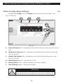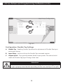
1
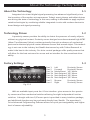
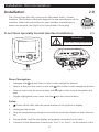
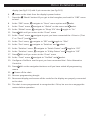
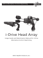
i-Drive Alternative Control Head Array
i-Drive Head Array
Usage Guide and Maintenance Manual for i-Drive
Alternative Control Head Array
2013 Stealth Products, Inc.
Copyright © 2013 Stealth Products, Inc.
All rights reserved.
Published by Stealth Products, Inc.
October 21, 2013
UMP-260813-R4
Stealth Products, Inc.
104 John Kelly Drive
Burnet, Texas 78611
Tel: (512) 715-9995
Toll Free: 1(800) 965-9229
Fax: (512) 715-9954
Toll Free: 1(800) 806-1225
Email: [email protected]
European Authorized Representative:
Boavista Solutions, Lda.
Ruo Engernheiro Ezequiel de Campos, 541-2°
Zona Industrial do Porto
4110-233 Porto
Portugal
Tel: +351 22 615 11 50
Fax: +351 22 615 11 52
Email: [email protected]
i-Drive™ is a trademark of Stealth Products, Inc.
Stealth Products® is a registered trademark of Stealth Products, Inc.
2
Table of Contents
Contents
1.0 Introduction ................................................................................................... 4
1.1
1.2
1.3
About the Technology........................................................................................4
Technology Driven ...............................................................................................5
Factory Settings ....................................................................................................5
2.1
2.2
2.3
Omni Installation ..................................................................................................6
Q-Logic Installation .............................................................................................8
Q-Logic Configuration .......................................................................................9
3.1
3.2
3.3
3.4
Getting Started ...................................................................................................11
Running the Setup Wizard .............................................................................15
Running Real-Time Diagnostics ...................................................................15
i-Drive Configuration Settings ......................................................................16
2.0 Installation ...................................................................................................... 6
3.0 i-Drive Advanced Programming Software .......................................11
4.0
5.0
6.0
7.0
8.0
9.0
Care and Maintenance.............................................................................19
Safety ..............................................................................................................19
Customer Satisfaction ..............................................................................19
Warranty Information...............................................................................20
Information Reference .............................................................................20
Note Section ................................................................................................21
3
Introduction: About the i-Drive
Introduction
1.0
The i-Drive is designed with the intent to provide mobility to those who need
it most. Utilizing stealth’s tried and true head positioning systems and revolutionary
technology developed by Trident Research, the i-Drive provides great support to the
head with the most diverse programmable head array ever.
Ultra-Pro
Tri-Array
i-Drive Control Unit
Attention!
Instructions are designed with the intended purpose of use with the standard configurations of i-Drive Head Arrays. For further assistance, or more
advanced steps in set-up, please contact us here at Stealth Products, Inc.
Telephone: (512) 715-9995
Toll Free: 1(800) 965-9229
4
About the Technology: Factory Settings
About the Technology
1.1
Integrated circuit and digital signal processing has advanced significantly since
the invention of the modern microprocessor. Today’s smart phones and tablet devices
are driving the state of technology in this area, making it affordable to apply sophisticated technologies by combining reliable integrated circuits with modern electronics
board design and signal processing.
Technology Driven
1.2
A proximity sensor provides the ability to detect the presence of nearby objects
without any physical contact. Proximity sensor designs have demonstrated high MTBF
(Mean Time Between Failure) numbers primarily through an absence of mechanical
parts and minimized physical contact between sensor and sensed object. This technology is not new to the industry but Stealth has teamed up with Trident Research to
make it the best in the industry. Our drive control packages offer quality sensors that
will allow for the best outcome for access and an interface for the smoothest driveability.
Factory Settings
1
2
3
1.3
4
5
Port 1
Port 2
Port 3a
Port 3b
Port 4a
Port 4b
Port 5
Port 6
6
Fig.1.3.1
Left
Forward
Mode/Reset
Not Assigned
Not Assigned
Not Assigned
Reverse
Right
Proximity Sensor
Proximity Sensor
1/8” Mono
1/8” Mono
1/8” Mono
1/8” Mono
Proximity Sensor
Proximity Sensor
With six available input ports the i-Drive interface gives access to four proximity sensors and four mechanical switches allowing for eight independent function
switches. A dongle with two 1/8”mono ports is provided in every interface package,
and additional dongles may be purchased directly from Stealth. The associated iDrive Advanced Programming Software allows for quick port assignability and higher
level of sensor adjustability.
5
Installation: Omni Installation
Installation
2.0
The i-Drive plugs into the 9 pin port on the power chair’s control
interface. The location of the port depends on the manufacturer of the
interface. Follow the instructions for your interface manufacturer in
these next sections. (see Fig2.0.1 for 9 pin female i-Drive plug)
Fig.2.0.1
R-net Omni Specialty Control Interface Installation
2.1
Attention!
R-Net OBP Dongle required
Fig.2.1.1
Fig.2.1.2
Menu Navigation
•
Navigate with
up and down on the circular navigation buttons
•
Return to the previous menu or exit with
left on the circular navigation buttons
•
Select a menu item for more options with
right on the circular navigation but-
tons
•
Toggle highlighted menu items with the
plus and minus buttons
Setup
1.
Power off the chair with the power button on the joystick or display
2. Disengage the motors
3. Plug the programming dongle in line with the cord from display to chair electronics
4. Ensure all the cords for the display are properly connected to the chair
5. Connect i-Drive Alternative Control into “Port 1” or “Port 2” on the bottom of the
6
Omni Installation (cont.)
display (see Fig.2.1.2) with 9-pin connector (see Fig.2.0.1)
6.
Power on the chair from the display’s power button
7. Press the
“Mode” button till you get to the hourglass, and wait for “OBP” menu
to load
8. In the “OBP” menu,
navigate to “Omni” menu option and
navigate to “Global” on the menu and
9. In the “Omni” menu,
navigate to “Sleep 12V” then
10. In the “Global” menu,
11. Press
select
select
toggle to “On”
left until you return to the “Omni” menu
navigate to port you have connected the i-Drive to (“Port
12. In the “Omni” menu,
1” or “Port 2”) and
select
13. In the “Port” menu,
navigate to “SID” and
toggle to “3Swi”
14. In the “Port” menu,
navigate to “Switches” and
select
15. In the “Switches” menu,
navigate to “Switch Detect” and
toggle to “Off”
16. In the “Switches” menu,
navigate to “9 Way Detect” and
toggle to “Off”
17. Press
left until you return to the “Omni” menu
18. In the “Omni” menu,
navigate to “Profiled” and
select
19. Configure a Profile to use the port you have connected the i-Drive Alternative
Control to
20. Press
left on the navigation buttons until you have exited all programming
menus
21.
Power off the chair
22. Remove programming dongle
23. Reconnect display, and ensure all the cords for the display are properly connected
to the chair
24. The chair is now programmed to recognize the i-Drive, be sure to re-engage the
motors before operation
7
Q-Logic Installation
Q-Logic Drive Control System Installation
2.2
Attention!
Q-Logic Handheld Programmer Required
Fig.2.2.1
Fig.2.2.2
Menu Navigation
•
Navigate the Main Menu with
•
Select a Main Menu item with
all direction buttons * Main Menu Only *
the three buttons under the display screen,
button actions are displayed on screen with corresponding labels * Main Menu
Only *
up and down on the navigation buttons
•
Navigate with
•
Return to the previous menu or exit with
•
Select a menu item for more options with
•
Toggle highlighted menu items with the plus and minus buttons
left on the navigation buttons
right on the navigation buttons
Setup
1.
Power off the chair with the power button on the joystick or display
2. Disengage the motors
3. Ensure all the cords for the display are properly connected to the chair
4. Connect i-Drive Alternative Control into the port on the bottom of the display
(see Fig.2.2.2) with 9-pin connector (see Fig.2.0.1 on p6)
5.
Power on the chair from the display’s power button
6. Plug in the Q-Logic Handheld Programmer to the back of the Q-Logic Display
7. On the Q-Logic Programmer
Select the “Program Adjustments” option
8. In the “Program Adjustments” menu,
select
8
navigate to “Specialty Control” and
Q-Logic Installation (cont.): Q-Logic Configuration
9. In the “Specialty Control” menu,
navigate to “Active Device” and toggle to
“3-Switch Head”
10. Press
left on the navigation buttons until you have returned to the main menu
11. Unplug the Q-Logic Handheld Programmer
12.
Power off the chair * Powering off the chair completely before operation is mandatory *
13. The chair is now programmed to recognize the i-Drive, be sure to re-engage the
motors before operation
Q-Logic Drive Control System Further Configuration
2.3
Back Pad Toggle
If you want to disable or enable the back pad’s ability to toggle into forward and
reverse:
1. Reconnect the Q-Logic Handheld Programmer (follows steps 1-7 from Setup)
Select the “Program Adjustments” option
2. On the Q-Logic Programmer
3. In the “Program Adjustments” menu, navigate
to “Specialty Control” and
select
navigate to “3-Switch Head” and
4. In the “Specialty Control” menu,
5. In the “3-Switch Head” menu,
navigate to “Back Switch Toggle” and
select
select
navigate to “m:Back Toggle” and toggle to
6. In the “Back Switch Toggle” menu,
“Enable” to enable forward/reverse toggle with the back pad, or toggle to “Disable” to disable toggle
7. After Configuring the back pad, disconnect the Q-Logic Programmer and restart
Chair Electronics (follow steps 10-13 from Setup), or continue to configure other
operations
9
Q-Logic Configuration (cont.)
Side Pad Toggle/Control
To disable or enable “Mode” switching with the side pad:
1. Reconnect the Q-Logic Handheld Programmer (follows steps 1-7 from Setup)
2. On the Q-Logic Programmer
Select the “Program Adjustments” option
3. In the “Program Adjustments” menu, navigate
to “Specialty Control” and
select
4. In the “Specialty Control” menu,
5. In the “3-Switch Head” menu,
navigate to “3-Switch Head” and
select
navigate to “Device Options / Timing” and
select
6. In the “Device Options / Timing” menu,
navigate to “m:Device Double Com-
mand” and toggle to “Enable” to enable mode switch with side pad, or toggle
to “Disable” to disable mode switch
7. After Configuring the back pad, disconnect the Q-Logic Programmer and restart
Chair Electronics (follow steps 10-13 from Setup), or continue to configure other
operations
Egg Switch Function
If you want to change the function of the egg swtich to switch “Mode” or
“Toggle” forward and reverse:
1. Reconnect the Q-Logic Handheld Programmer (follows steps 1-7 from Setup)
2. On the Q-Logic Programmer
Select the “Program Adjustments” option
3. In the “Program Adjustments” menu, navigate
to “Specialty Control” and
select
4. In the “Specialty Control” menu,
5. In the “3-Switch Head” menu,
navigate to “3-Switch Head” and
select
navigate to “Switch Options / Timing” and
select
6. In the “Switch Options / Timing” menu,
navigate to “m:Mode Jack Switch Type”
and toggle to “Mode” to enable mode switch with the Egg Switch, or toggle to
“Toggle” for forward/reverse toggle
1. After Configuring the back pad, disconnect the Q-Logic Programmer and restart
Chair Electronics (follow steps 10-13 from Setup), or continue to configure other
operations
10
i-Drive Advanced Programming Software
i-Drive Advanced Programming Software
3.0
The i-Drive’s advanced programming software is not required to operate the drive
control, but is available to ensure a customized fit and driving experience. Programming the i-Drive is simple. By connecting a tablet or smartphone and using the i-Drive
Advanced Programming Software application you can:
•
Dynamic Channel Assignment—any port can control any of the 5 outputs
•
Adjust Activation Proximity—Change the range of motion required for switch
activation
•
Provide an adjustable double tap feature that extends chair double tap limits
•
Configuration—Program by Bluetooth (available soon)
•
Attendant Control via Bluetooth (available soon)
Getting Started
3.1
The first step to begin use of the i-Drive Head Array Programmer is downloading
the software. Included with your i-Drive head control system should be a card with a
link to download the application. If there are any difficulties obtaining software, contact Stealth Products, Inc.
After the Software has been installed onto your device, you can begin utilizing the
Advanced Programming Software. Launch the “iDrive Head Array Programmer”
application on your device, and with a USB to Mini-USB cable, connect the i-Drive
to your PC or Tablet. Allow time for the i-Drive to make a full connection with your
computer.
Warning!
Please manually disengage both drive motors before
utilizing the Setup Wizard, Diagnostics and Config. If
motors are not disengage, chair could move during setup.
11
i-Drive Advanced Programming Software (cont.)
Fig.3.1.1
Connecting to the i-Drive
After adequate time is given to allow the i-Drive to connect to your computer,
and you have launched the application click the connect button. (It may be required to
change the “COM” in the drop-down menu next to the connect button, see Fig.3.1.1)
Fig.3.1.2
Setup Wizard Feature
The Setup Wizard (see Fig.3.1.2) will guide you through the initial port configuration and channel assignment of the i-Drive Head Array.
12
i-Drive Advanced Programming Software (cont.)
Fig.3.1.3
Diagnostics Feature
With real time Diagnostics (see Fig.3.1.3) you are able to observe pad behavior
as the head array is activated by the user. This is useful to fine tune the i-Drive and
confirm it is operating properly.
Fig.3.1.4
Configuration Feature
Head array Configuration (see Fig.3.1.4) allows you to adjust the way the i-Drive
activates and allows you to fine tune the function and sensitivity of the head array.
13
i-Drive Advanced Programming Software (cont.)
Help Feature
Fig.3.1.5
Clicking the Help button (see Fig.3.1.5) will activate help. When help is active, the
help button will be green and a question mark will be displayed next to your cursor.
With help mode active, clicking buttons and menu items will pop-up with an explanation of what the clicked object is and how it can be utilized. To disable help, click on
the help button again. (help button will be black when inactive and green when active)
Fig.3.1.6
Closing the i-Drive Head Array Programmer
When you are finished configuring the i-Drive, you can click the Quit button in
the bottom right of the screen to close the application. (see Fig.3.1.6)
14
i-Drive Advanced Programming Software (cont.)
Running the Setup Wizard
3.2
The Setup Wizard will guide you through the ini-
tial port configuration and channel assignment of the
i-Drive Head Array. To begin the Setup Wizard, click
the Setup Wizard button on the left of the screen. (see
Fig.3.1.2 on p12)
The Setup Wizard window will pop-up on screen.
Fig.3.2.1
(see Fig.3.2.1) The Setup Wizard will walk you through
a 7 step setup process. Follow the instructions on
screen or push Cancel to quit Setup.
Running Real-Time Diagnostics
3.3
To begin the Diagnostics, click the Diagnostics button on the left of the screen.
(see Fig.3.1.3 on p13)
D
B
C
A
Fig.3.3.1
A. Mode Switch activation
B. Left, Right, and Back pad activation
C. Corresponding i-Drive port when switch is pressed
D. Double-Tap Calibration
Attention!
Double-Tap needs to be enabled in the Configuration menu
Double-Tap Settings before Double-Tap Calibration can be used.
15
i-Drive Advanced Programming Software (cont.)
i-Drive Configuration Settings
3.4
To begin the Config, click the Config button on the left of the screen. (see
Fig.3.1.4 on p13)
A
B
C
D
E
F
Fig.3.4.1
A. Sensor Channels Tab - Navigates to the Sensor Channels menu (see Fig.3.4.2 on
p17)
B. Mechanical Channels Tab - Navigates to the Mechanical Channels menu (see
Fig.3.4.3 on p17)
C. Double-Tap Settings Tab - Navigates to the Double-Tap Settings menu (see
Fig.3.4.4 on p18)
D. Reboot Device Button - Reboots the i-Drive
E. Factory Reset Button - Resets all settings to factory default
F.
Save Settings Button - Saves your settings
Attention!
Be sure to save your settings with the Save Settings button
after all the desired changes are made. (see D on Fig.3.4.1)
16
i-Drive Advanced Programming Software (cont.)
A
B
C
D
Fig.3.4.2
Configuration: Sensor Channels
A. Diagram that shows which channel switches are being modified
B. Drop down menus that allow you to assign function per channel
C. Sensor Sensitivity - Slider that changes the sensitivity of the selected channel
D. Changes the selected Channel for the sensitivity slider C
A
B
Fig.3.4.3
Configuration: Mechanical Channels
A. Diagram that shows which channel switches are being modified
B. Drop down menus that allow you to assign function per channel. Mechanical
Channels have 2 inputs by dongle.
17
i-Drive Advanced Programming Software (cont.)
A
B
C
Fig.3.4.4
Configuration: Double-Tap Settings
A. Double Tap - Enabling Double-Tap allows for adjustment of Double-Tap input
and output timing.
B. Input Delay - Amount of time for Double-Tap command capture.
C. Output Speed - Time period between Mode output pulses. This value should
match the Double-Tap Input Timing of the chair.
Attention!
It’s recommended to use Calibrate Double-Tap option in the Diagnostics
to get a properly timed double tap setting for the user. (see Fig.3.3.1 on p15)
18
Care, Maintenance, Safety and Customer Satisfaction
Care and Maintenance
4.0
Ensure the hardware you’re using stays in working order by keeping it cared for
and maintained.
•
Keep electronics dry and out of water. Getting electronics wet will cause irreversible damage to the circuitry.
•
Periodically check the hardware for loose screws or worn parts. Replace or repair
the parts as needed.
•
To clean aluminum, use a mild nonabrasive household cleanser (without getting
electronics wet.)
•
To wash covers: remove cover from the pad, machine wash cold on a delicate
cycle and drip dry afterwards.
•
On the hardware, lightly tighten set screws until they are snug, then tighten an
extra quarter turn. Do not over tighten set screws! Over tightening set screws will
prevent hardware from functioning properly and could cause irreversibly damage
the hardware.
Safety
5.0
Avoid getting electronics wet and working with electronics with wet or damp
hands, this could cause minor to sever electrocution resulting in personal injury and/
or product damage.
Customer Satisfaction
6.0
Here at Stealth Products, we pride ourselves on 100% customer satisfaction. Your
complete satisfaction is important to us, so please feel free to offer any feedback or
suggested changes that will help improve the quality and usability of our i-Drive products. You may reach us at:
104 John Kelly Drive, Burnet, Texas 78611
Phone: (512) 715-9995
Toll Free: 1(800) 965-9229
Fax: (512) 715-9954
Toll Free: 1(800) 806-1225
[email protected]
19
Warranty and Reference Information
Warranty
7.0
Stealth Products, Inc. warrants this product against failure due to defective materials or workmanship as follows:
Covers
180 Days
Hardware
5 Years
Electronics
5 Years
Limitations
Stealth Products, Inc. does not warrant damage due to, but not limited to:
•
Misuse, abuse or misapplication of products .
•
Modification of product without written approval from Stealth Products, Inc .
•
Any alteration or lack of serial number where applicable will automatically void
this warranty .
•
Stealth Products, Inc. is liable for replacement parts only .
•
Stealth Products, Inc. is not liable for any incurred labor costs.
Caution!
These products are designed to be fitted, applied and installed exclusively by a health care professional trained for
the purposes. The Fitting, application and installation by a
non qualified individual could result in serious injury.
Information Reference
Serial NO (SN#):
Chair Manufacturer:
Purchase NO (PO#):
8.0
Purchase Date:
Model:
Sales Order NO (SO#):
20
Notes
Notes
9.0
21
Notes
22
Notes
23
i-Drive Alternative Control Head Array
Stealth Products, Inc.
104 John Kelly Drive
Burnet, Texas 78611
www.stealthproducts.com
[email protected]
Tel: (512) 715-9995
Toll Free: 1(800) 965-9229
Fax: (512) 715-9954
Toll Free: 1(800) 806-1225
UMP-260813-R4