1
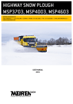
HIGHWAY SNOW PLOUGH MSK3703, MSK4003, MSK4603 y MEIREN ENGINEERING OÜ VÄIKE-MÄNNIKU 7/// 11216 TALLINN /// ESTONIA /// PHONE +372 682 5002 /// FAX +372 610 0589 /// EMAIL [email protected] /// WWW.MEIRENSNOW.COM USER MANUAL 2015 This user manual applies for snow ploughs from serial number 0891XXXXX HIGHWAY SNOW PLOUGH MSK03 CONTENT CE DECLARATION OF CONFORMITY ..................................................................................................................... 3 FOREWORD ........................................................................................................................................................ 4 GENERAL SAFETY REQUIREMENTS ..................................................................................................................... 4 PERSONNEL ....................................................................................................................................................... 4 1. PRODUCT DESCRIPTION ............................................................................................................................. 5 1.1. 1.2. HIGHWAY SNOW PLOUGH IN STANDARD EQUIPMENT .................................................................................................. 8 ACCESSORY EQUIPMENT ....................................................................................................................................... 8 2. SAFETY REQUIREMENTS FOR OPERATING THE SNOW PLOUGH .................................................................. 8 3. MOUNTING AND DEMOUNTING OF A PLOUGH ........................................................................................... 10 4. WORKING WITH THE PLOUGH................................................................................................................... 12 4.1. 4.2. 4.3. 4.4. 5. MAINTENANCE ......................................................................................................................................... 17 5.1. 6. TRANSPORTING THE SNOW PLOUGH ...................................................................................................................... 13 USAGE OF SKID SHOE ......................................................................................................................................... 13 WORKING WITH AN ADDITIONAL BLADE .................................................................................................................. 14 DESCRIPTION AND USE OF HARDOX RUBBER BLADES ............................................................................................... 16 GREASE POINTS ................................................................................................................................................ 18 WARRANTY CONDITIONS .......................................................................................................................... 19 TABELS Table 1. Technical specifications of the snow plough................................................................................................................... 7 Table 2. MSK series recommended working modes for the additional blade .........................................................................16 Table 3. Maintenance plan of the snow plough............................................................................................................................17 DRAWINGS Drawing 1. Fastening of the blade holder ....................................................................................................................................... 5 Drawing 2. Rotation axle of the blade .............................................................................................................................................. 6 Drawing 3. Side blade ......................................................................................................................................................................... 6 Drawing 4. Side support ..................................................................................................................................................................... 7 Drawing 5. Safety marking: RISK OF ACCIDENT! ............................................................................................................................. 9 Drawing 6. Mounting and demounting of a plough (Finnish fastening system) ...................................................................11 Drawing 7. Switching valve ..............................................................................................................................................................12 Drawing 8. Marking of the lifting eye .............................................................................................................................................13 Drawing 9. Usage of the skid shoe .................................................................................................................................................14 Drawing 10. Additional blade ..........................................................................................................................................................15 Drawing 11. Hydraulic unit of the additional blade. ....................................................................................................................15 Drawing 12. Manometer...................................................................................................................................................................16 Drawing 13. Hardox rubber blade ...................................................................................................................................................17 Drawing 14. Grease points ..............................................................................................................................................................18 2 WWW.MEIRENSNOW.COM HIGHWAY SNOW PLOUGH MSK03 CE DECLARATION OF CONFORMITY Manufacturer: Meiren Engineering OÜ Väike-Männiku 7 11216 Tallinn Phone +372 682 5002 www.meirensnow.com We hereby declare that the below mentioned product: Highway snow plough MSK Model: ............................................ Serial number: ............................................ Manufacturing date: ............................................ Meets the following directives and standards: 2006/42/EC EN 349:1993+A1:2008 3 WWW.MEIRENSNOW.COM HIGHWAY SNOW PLOUGH MSK03 FOREWORD Thank you for choosing the Meiren Snow product. This operator manual consists of technical specifications, user and maintenance instructions and warranty terms and conditions of MSK03 series snow plough. MSK03 series snow ploughs are designed for removing loose snow from surfaced roads. The product is not suitable for removing sand, gravel, ice or other similar material. Using the plough contrary to its intended purpose may cause economic losses and bodily injuries. It is therefore of the utmost importance that the person operating the plough read through the manual and use the product pursuant to the requirements. Any misuse of the product releases the manufacturer from the liability for occurred damages and for reimbursing losses. GENERAL SAFETY REQUIREMENTS As the construction of the product is complex and it contains moving parts, it is very important that the person working with the equipment be aware of all the safety risks. To reduce the risks, it is important that the operator have read through the operator manual; the operator have been completed an appropriate training, which gives him/her the permit to use a product of this type in his/her work; the operator have been provided with all necessary tools and is wearing appropriate work clothes. PERSONNEL This product may only be used and maintained by properly trained personnel. The operator’s employer is obliged to ensure fulfilment of all user instructions and safety requirements set out by the manufacturer. Please read carefully through the operator’s manual before starting working with the snow plough. 4 WWW.MEIRENSNOW.COM HIGHWAY SNOW PLOUGH MSK03 1. PRODUCT DESCRIPTION Highway snow ploughs MSK3703, MSK4003 and MSK4603 are durable snow ploughs with a conical steel frame, partially plastic mouldboard and plastic screen intended for professional use on hard-paved highways. The blade angle of MSK03 series snow ploughs with respect to the ground is 45–50°, which ensures that snow is effectively removed from the pavement. The conical mouldboard of MSK03 series snow ploughs ensures greater snow discharge distance, thus reducing the formation of snow-walls. The optimal shape of the plough ensures economic efficiency and smooth operation even at speeds up to 70 km/h. The partially plastic flaps are less prone to rust than steel flaps, they produce less noise and also weigh less. Special cold- and wear-resistant plastic sheet is used for plastic material. The snow plough marking indexes 3703, 4003 and 4603 indicate the approximate total width of the plough's flap blades in millimetres. MSK03 series model is equipped with interchangeable blade holders with noise reducers (Drawing 1). There is a 45 mm thick special cast rubber band (3) between the blade holder (1) and flap (2), which reduces noise and makes the movement of the blade (11) more elastic with respect to the road surface. This, in turn, improves the quality of ploughing and protects the marking of the road surface from extensive wear and tear. Blade holders are attached to the flap with fasteners (4, 7, 8, and 9). Elastic movement of the blade holder is ensured by a spherical washer (10). In order to prevent noise from transferring to the flap via bolts, there are steel-rubber bushings (5, 6) in bolt openings. The joints of the lifting frame (parallelogram) on the vehicle side are equipped with rubber bushings to further reduce further noise and vibration transferred to the cabin. The blade is fixed to the blade holder as regular: either with wedge bolts or other type of bolts. In order to prevent the blade holder from wearing out too much when the blade wears away, there are wear-resistant steel support plates underneath the blade holder, which decrease the speed in which the blade holder wears away (these are not designed to be used as a sliding soleplate). Drawing 1. Fastening of the blade holder This plough type differs from ploughs made by other manufacturers by a special fastening method of the blade to the lifting frame (parallelogram). We use a spherical slide bearing, which ensures turning of the blade with a cylinder, as well as lateral tilting of the plough when the inclination of the road changes. For this purpose there is a polyurethane axle pad (1, Drawing 2) installed in the upper part of the rotation axle of the blade. This axle pad ensures tilting of the blade approximately two degrees in both directions during work, following the road profile and when lifted up the axle pad prevents excessive swinging of the blade. The axle pad also reduces vibration generated during the plough work. 5 WWW.MEIRENSNOW.COM HIGHWAY SNOW PLOUGH MSK03 1 . Drawing 2. Rotation axle of the blade The right side of the moldboard is equipped with replaceable side blade (1, Drawing 3), which simplify cleaning of curbstones of the pavement. The edges of the side blades are reinforced with hard alloy coating round profiles, which ensure smooth, shock-free cleaning of curbstones. 1 . Drawing 3. Side blade The left side of the mouldboard is equipped with a replaceable side support (1, Drawing 4) that is designed to support the mouldboard and prevent the blades from touching the ground when driving on soft ground. 6 WWW.MEIRENSNOW.COM HIGHWAY SNOW PLOUGH MSK03 1 Drawing 4. Side support MSK03 series is provided with a hydraulic side impact protection mechanism (7, Drawing 6), the function of which is to reduce shock impact on the blade tip in the event of contact with curbstones for instance. The impact protection mechanism enables elastic turning of the plough skirting for up to 3 degrees when the rotational cylinders’ rods are at a distance of 50...100 mm from their extreme positions. The plough is made of high-strength steel. For manufacturing the moldboard, wear-resistant special steel is also used. The product is finished with high wear-resistant paint. MSK3703 MSK4003 MSK4603 Total width of the plough flap blades, mm 3660 3965 4575 Plough flap working width at max. swivel angle, mm 2730 2950 3410 Total width of the plough flap, mm 4370 4680 5300 Height of the plough flap in the right corner (with blades), mm 1530 1570 1620 Height of the plough flap in the left corner (with blades), mm 850 830 780 Maximum swivel angle (both side), ° 40…44 Angle of blades with respect to road surface, ° Total weight of the plough (without blades and accessories), kg Recommended operating pressure of the hydraulic system, bar Recommended output capacity of the hydraulic pump, l/min 46 1074 1112 1190 160...200 30...50 Table 1. Technical specifications of the snow plough 7 WWW.MEIRENSNOW.COM HIGHWAY SNOW PLOUGH MSK03 1.1. Highway snow plough in standard equipment Parallelogram (lifting frame of the plough) A moldboard with two rotation cylinders and a lifting cylinder ⅜’’ -inch hoses with ½-inch quick couplers Replaceable side blades Safety marking and LED side lights Colour: yellow, RAL 1007 A hydraulic impact protection valve of the rotation cylinder with a hydraulic battery to reduce lateral impact 1.2. Accessory equipment A skid shoe with hard alloy plate and an adjustment mechanism; A set of steel blades (made of hard alloy or as per customer's request) Hydraulic mechanism for the additional blade (possibility to adjust blade pressure applied on the road surface) A set of hydraulic skid shoe for lifting frame A set of hydraulic support leg A set of rubber cutting edges (a special plough rubber with a thickness of 40 or 50 mm) for the additional blade Electrical additional valve to control the additional blade (if the vehicle is not provided with three pairs of hydraulic outlets). NB! For the additional blade, the car needs to have three pairs of hydraulic spool valves or an additional valve for controlling the additional blade! 2. SAFETY REQUIREMENTS FOR OPERATING THE SNOW PLOUGH Before operating the snow plough Check the integrity and technical condition of the snow plough. It is prohibited to commence work with a device that is not in good technical condition. Check that there are no people or objects near the snow plough that the plough might injure or damage. In addition, safety of people carrying out maintenance of the snow plough, repairing the snow plough or moving it with the help of hydraulics or any other lifting mechanism has to be ensured. Failure to follow safety requirements may result in causing injuries to people (the snow plough is provided with safety markings, see Drawing 5). It is prohibited to work under a lifted snow plough, if the plough is not supported. Check that the snow plough is properly fastened to the vehicle and the fasteners are not damaged. Check the condition and visibility of safety marking, position lamps (if available) and reflex reflectors. Check the condition of the blades (also the condition of sliding soleplates or wheels, if available). Worn blades must be adjusted downward, turned around or replaced, so as not to damage the blade holder. Check the blade cotters. Check the fasteners of levers and cylinders. Check that the hydraulic hoses are intact and properly fastened. Check that the snow plough is properly greased. Check that the snow plough has no damages. 8 WWW.MEIRENSNOW.COM HIGHWAY SNOW PLOUGH MSK03 Working with the snow plough The snow plough may only be used by a person, who is at least 18 years of age, holds a driver's license in the respective category and has familiarised himself/herself with the operator’s manual of the snow plough. Make sure to always pay attention to the surrounding area and other traffic, including vehicles approaching from side roads and behind. Pay attention to pedestrians and cyclists, so as not to put them in danger while working with the snow plough. All warning lights must be switched on at all times while working! Adhere to general traffic regulations. The maximum operating speed for the snow plough in normal road conditions on hard-paved roads is 70 km/h. Reduce speed when working on soft surfaces, because the blades may cut into the ground, the driver may lose control of the vehicle and the vehicle may run off the road. If working on a soft surface, the plough should be supported on sliding soleplates, wheels or additional blades. The snow plough may only be used to plough loose snow! It is prohibited to plough ice, frozen snowdrifts, rocks, gravel, sand, etc. It is prohibited to plough snow banks at maximum operating speed since this may damage the snow plough. The manufacturer shall not be liable for any damages caused by overloading the snow plough. If the highway snow plough is used in the city or on uneven roads, where there is risk of damaging the vehicle and road surface, it will be done at the user's own liability. The manufacturer shall not be liable for any damages caused by the abovementioned. It is prohibited to attach such accessory equipment to the movable parts of the snow plough that the manufacturer has not approved. It is prohibited to use hydraulically operating devices as lifting jack. The snow plough may only be lifted from lifting eyes. Each time there is an incident during operation that may damage the equipment, an inspection of the equipment shall be arranged in order to detect and assess possible damages. Damages (cracks in the structure or welded joints, deformed parts) may put property and people's health in danger. It is prohibited to continue work until the damages are repaired. Drawing 5. Safety marking: RISK OF ACCIDENT! 9 WWW.MEIRENSNOW.COM HIGHWAY SNOW PLOUGH MSK03 3. MOUNTING AND DEMOUNTING OF A PLOUGH Mounting of a plough on the truck or tractor (Drawing 6) To mount the plough the vehicle must stand on a level surface. Drive the vehicle as close to the lifting frame of the plough as possible and connect the hydraulic hoses to the quick coupler of the vehicle. Lift the coupling frame of the plough to such a height that the fastening eyes (3) are over the upper edge of the coupling frame of the vehicle. Drive the frame of the vehicle against the frame of the plough and lift the plough with lifting cylinders onto the frame of the vehicle. Check that the fastening eyes (3) are correctly positioned and lock the frame (5) of the plough on the frame of the vehicle (as the locking systems of ploughs may differ depending on the country please follow the applicable requirements). Remove the pin (2) of the lifting cylinder and store it in a holder. Do not leave the pin attached to the cylinder during work! The pin should only be used to mount and demount the plough. If the pin is not removed for the work, the plough will not follow the uneven profile the road and the pin may break. You may leave the pin in place at your own responsibility only in the event the plough is equipped with a hydraulic floating system and the lifting cylinder does not press the plough against the ground. Demounting of a plough from the truck or vehicle (Drawing 6) Install the pin (2) in the control surface opening of the lifting cylinder (1). Place the plough on an even ground, the cutting edge must rest on the ground and install the support leg (6) of the plough close to the ground (approx. 20-30 mm from the ground). If you install the support leg completely against the ground when you demount the blade, it is later more difficult to mount the blade on the vehicle (the fastening plate of the plough will be positioned too vertically). In the event of additional blades (8) it is recommended to lower the additional blades to the same plane as the front blade to ensure greater stability of the snow plough Loosen the fastening bolts or pins (5) of the frame of the vehicle. Lift up the frame (3) of the plough from the frame of the vehicle with the help of the lifting cylinder. Disconnect the hoses and drive further. NB! It is forbidden to lift up the plough with a pin, since the pin is not designed to support this heavy loads and it will bend through. 10 WWW.MEIRENSNOW.COM HIGHWAY SNOW PLOUGH MSK03 Drawing 6. Mounting and demounting of a plough (Finnish fastening system) Using the hydraulic support leg of the parallelogram In order to activate the hydraulic support leg, the hydraulic supply system needs to be switched from lift cylinder control to support leg control. This is done by using the switching valve on the parallelogram of the plough (1, Drawing 7). Turning the valve lever to the right towards the vehicle (as shown in the drawing) activates the lift cylinder, turning the lever to the left activates the support leg of the parallelogram. 11 WWW.MEIRENSNOW.COM HIGHWAY SNOW PLOUGH MSK03 Drawing 7. Switching valve 4. WORKING WITH THE PLOUGH The plough is provided with a lifting cylinder (1, Drawing 6) giving the plough an option of a mechanically floating position. On the piston rod side of the cylinder there are control surfaces that enable the plough to move up and down (float) following the profile of the road surface. In order to ensure floatability the weight of the plough shall not fall on the lifting cylinder but the cylinder shall be in a retracted position and free during work. Before starting work check the pressure of the tyre, if the machine is equipped with a support wheel. The pressure must be 10 bar. In the event of sharp temperature changes the tyre pressure has to be re-checked. It is very important to use proper working methods and not to overload the plough. For removing thick and heavy snow choose suitable (slow) speed and pay constant attention to the consistency of the snow. For removing wet snow and sleet make more use of the additional blade made of rubber. The pressure of the additional blade of the MSK series ploughs may only be adjusted when the front steel blade is in no contact with the ground surface. Yet the additional plough may still get clogged when the front blades are too high up from the ground and the additional blade must remove all the snow. Do not use the additional blade on dry asphalt, since it may cause jerky movement of the plough and the additional blade may wear off too quickly. On ploughs equipped with a rubber additional blade we recommend to use hard alloy blades, since these are more wear resistant. On models with slide feet also standard steel blades may be used, if the weight of the plough does not fall on the blades. It is not recommended to fully retract or extend the rotation cylinder during work. Approx. 100 mm has to be left for the cylinder travel. In this way it is possible to use the safety valve of the rotation cylinder to reduce more efficiently impacts of possible obstacles. If the plough is driven against an obstacle with a side, the rotation cylinder in the end position may damage the plough and the vehicle. In case the plough is driven on a rigid obstacle, the fastening bolts (4, Drawing 1) of the blade holder may break, yet the structure itself will not get major damages and in most cases the plastic safety straps will keep the blade holder hanging on the blade. 12 WWW.MEIRENSNOW.COM HIGHWAY SNOW PLOUGH MSK03 4.1. Transporting the snow plough MSK03 series snow ploughs all have lifting eyes for transporting the plough marked with a corresponding marking (Drawing 8). In order to transport the plough in cargo or a container, first remove the screen (8, Drawing 6) to fit the plough into the cargo. Drawing 8. Marking of the lifting eye 4.2. Usage of skid shoe The wheel or slide feet must be adjusted so that the steel cutting edge is 0-15 mm higher from the ground (depending on the road surface). The function of the wheel mechanism spring (2, Drawing 9) is to pull the wheel closer to the blade when it is in the transport position. The tightness of the spring can be adjusted but the spring must not be this loose that the wheel gets in contact with the vehicle when the plough is lifted up. Regarding the skid shoe it has to be verified that it does not wear off too quickly since the foot may break and fall off. After adjustment of the wheel or skid shoe, do not forget to install the handle splint (2) to ensure that the wheel or foot remains in the desired position. Support wheels cannot be used with an additional blade. 13 WWW.MEIRENSNOW.COM HIGHWAY SNOW PLOUGH MSK03 Drawing 9. Usage of the skid shoe 4.3. Working with an additional blade MSK03 series snow ploughs may be equipped with a hydraulic blade (additional equipment), which gives better and cleaner ploughing result. In certain weather conditions (sleet and wet snow) it is only permitted to use an additional blade, whereas the front blade must be lifted up from the ground. The additional blade can be equipped with a rubber blade with the thickness of 40-50 mm and made of special rubber mix. The blade holder has a mounting plate (1, Drawing 9) for attaching the rubber strap: the rubber sheet is pressed to the mounting plate with the help of bolts (2). When you use such fastening method there is no need to make bolt openings in the rubber blades. Compared to the products made by competitors, it takes much less time to replace the rubber blades of this type of a plough. It is also possible to lower the worn blade, which enables maximum use of the entire wearing material. 14 WWW.MEIRENSNOW.COM HIGHWAY SNOW PLOUGH MSK03 Drawing 10. Additional blade Adjustment of working pressure of the additional blade For installing a hydraulic additional blade LH, the vehicle must be equipped with three distributor sections (six quick coupler parts). The capacity of the hydraulic pump must not exceed 50 l/min., since otherwise the blade will move too fast up and down. With the help of hydraulic cylinders of the additional blade it is possible to lift up the pressure valve (1, Drawing 11) of the front blade. To adjust the pressure remove the valve cap and adjust the pressure with an Allen by pressing at the same time the additional blade towards the ground (or to the lower end position). To increase the pressure in cylinders, turn the screw clockwise. The hydraulic system of the additional blade is equipped with two hydraulic batteries (2, Drawing 11), which ensure flexibility of the additional blade in the desired pressure conditions. During adjusting you can use connection point (3, Drawing 10) of the pressure gauge to measure the pressure. After flap adjustment the additional blade should be moved up and down to make sure it has been adjusted properly. Its optimal pressure on the ground surface is listed in the table below. The operating modes are recommended and they also depend on the road surface properties, amount of salt used, etc. The driver should select the operating modes taking into account the local conditions and personal work experience. When the road is uneven and plenty of salt is used, the pressure of the additional blade should be raised (24-45 bar). Drawing 11. Hydraulic unit of the additional blade. Hydraulic system must be filled with hydraulic oil ISO VG 32 15 WWW.MEIRENSNOW.COM HIGHWAY SNOW PLOUGH MSK03 Recommended additional blade operating modes Weather conditions Wet snow, snow layer 2-3 cm Wet snow, snow layer 4-5 cm temperature range from -1 °C to +1 °C Loose snow, 3-7 cm temperature range from -15° to 0°C Compacted snow, ice temperature range from -25° to 0°C Additional blade’s pressure on ground surface, % compared to frontal blade 100% (raise the frontal blade from the surface) Additional blade’s operating pressure, bar 60-90% 30-45 30-70% 20-35 0% 0 60-90 Table 2. MSK series recommended working modes for the additional blade When the additional blade’s flap pressure is set to 40-45° bar, thus raising the frontal blade from the surface, the additional blade can be pressed down in a weaker manner, maintaining the contact of the frontal blade with the surface. The success of this depends on the driver’s skills; it is not a precise operation and may not ensure the desired pressure distribution between the frontal and rear blades. Drawing 12. Manometer 4.4. Description and use of Hardox rubber blades Hardox rubber blades are highly durable rubber blades with Hardox metal reinforcement that withstand difficult conditions better than standard rubber blades and ensure significantly longer lifetime thanks to wear resistant metal. Hardox blade is suitable for use instead of rubber blade with all snow ploughs. Hardox rubber blade includes steel blade segments surrounded by rubber. Hardox rubber blade can be used on both sides up to the red area marked on the blade. If one side of the blade is worn out up to the red area, turn the blade over and use the other side until it reaches the red area. Hardox rubber blade wear must not exceed the red line, i.e. 70 mm on both sides. 16 WWW.MEIRENSNOW.COM HIGHWAY SNOW PLOUGH MSK03 Drawing 13. Hardox rubber blade 5. MAINTENANCE MAINTENANCE IN EVERY 8 WORKING HOURS MAINTENANCE IN EVERY 150 WORKING HOURS Check all bolt connections and hydraulic connections and tighten, if required. If the plough is provided with wheels, check the bearing play of the wheels (see the spare parts catalogue, Drawing 6). If the play is too big disassemble the wheel hub (10), check the bearings (30) and adjust the play (for adjusting use a nut (25) and a special locking washer (24) with pegs. Check that there are no leakages in the hydraulic system. If required, tighten the connections of the hydraulic parts and hose ends. Check all bolt connections and tighten, if required. Check the condition of the fastening bolts of the blade holders. The bolt (4, Drawing 1) torque must be approximately 60. Before tightening and controlling loosen the locknut. Check all bolt connections and tighten, if required. Check that there are no leakages in the hydraulic system. If required, tighten the connections of the hydraulic parts and hose ends. Spray the zinc coated parts, hydraulic valves and hose ends with rust resistant wax. Check the condition and fastening of the cutting edges. If required adjust the cutting edges or replace these. Grease all grease points: bearings of the rotation and lifting cylinder of the blade, for Norwegian and Danish fastenings also the bearing of the coupling frame. If the plough is provided with slide feet and wheels grease the regulating mechanism. Check the condition and fastening of the cutting edges. If required adjust the cutting edges or replace these. X X X X X X X X X X MAJOR SEASONAL MAINTENANCE Grease all grease points. Also grease or wax the extended adjustment surfaces of the internal pipe of the wheel mechanism. Check the plough visually and see if there are parts that need to be replaced. Repair all paint damages. Retract the piston rod of the cylinder and cover it with proper grease. Store the plough in a place exposed to winds but protected from rain and UV rays. Check that the hoses are pressure released. Table 3. Maintenance plan of the snow plough 17 WWW.MEIRENSNOW.COM HIGHWAY SNOW PLOUGH MSK03 5.1. Grease points Drawing 14. Grease points Pos. nr 1 2 3 4 5 6 7 8 9 Location Midframe Lift cylinder Bracket bearings Right pivot cylinder Bracket pins Left pivot cylinder Right skid shoe Left skid shoe Snow flow guide cylinder In all Quantity 4 1 4 2 2 2 1 1 2 19 18 WWW.MEIRENSNOW.COM HIGHWAY SNOW PLOUGH MSK03 6. WARRANTY CONDITIONS The Seller gives the Product a guarantee for a term of 12 (twelve) months. The guarantee term starts upon delivery of the Product to the Buyer and the time of delivery is the date indicated in the deed of delivery and receipt or CMR. The guarantee covers the elimination by the Seller of any production, material or construction defects detected in the Product or details thereof during the guarantee period. The Seller is obligated to replace the defective Product with a new one only if the repairing of the Product or a detail or replacing of a detail is not possible. The Buyer undertakes to inform the Seller in writing of any defects detected during the guarantee term within seven (7) calendar days as of learning of the defect, describing the defect in sufficient detail. The Seller is obligated to carry out an expert assessment to identify the causes of the defect within fourteen (14) working days after the receipt of the written notice. In the event of a defect covered by the guarantee the Seller eliminates it within twenty (20) working days after the expert assessment. The performance of repair work under the guarantee takes place at the delivery address specified in the Order Confirmation. Major repairs are made in the territory of the Seller. The cost of transportation of the Product to the place of guarantee repairs is borne by the Buyer. The Buyer bears the costs of repairs exceeding the terms and conditions of guarantee repairs and the transportation costs. The following defects are not covered by the guarantee: – defects arising from the natural wear and tear of the Product; – defects arising from the characteristics or damages of the road cover; – defects arising from the use of the Product in conflict with its technical conditions, security rules and purpose; – defects arising from disregarding the rules of maintenance of the Product; – defects arising from a traffic accident; – defects of which the Buyer has not informed the Seller in writing within seven (7) days as of the emergence of the defect and/or whereby the Buyer has not given the Seller the chance to identify the cause of the defect in accordance with the Agreement. – to the extent whose expansion the Buyer could have reasonably prevented. The Product guarantee term terminates before the prescribed time as of the time when: – the Product has been independently repaired, without coordinating it with the Seller in writing beforehand; – the constructions of the Product have been changed, additional equipment has and/or spare parts have been installed without coordinating it with the Seller in writing in advance. If the Seller, in spite of repeated written inquiries by the Buyer, fails to perform its guarantee obligations arising from the Agreement, the Buyer shall have the right to eliminate the Product's defect at the Seller's expense. The Buyer must inform the Seller in writing at least five (5) working days before the replacement or repairing of a defective Product and submit to the Seller a calculation of the presumable reasonable costs. The Buyer may withdraw from the Agreement and demand that the Product be taken back and the Purchase Price refunded only if the defect cannot be eliminate or the part cannot be replaced and if replacement of the defective Product with a new Product would not produce the results that would allow for the purposeful use of the Product. The Product or a part thereof replaced during the guarantee term is covered by the guarantee until the expiry of the overall guarantee term of the Product. 19 WWW.MEIRENSNOW.COM