1
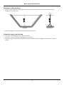
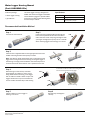
Water Logger Housing Manual
(Part # HOUSING-U2x)
Inside this package:
• Water logger housing
• (6) Cable ties
The water logger housing is designed for
HOBO® U20 water level loggers and HOBO®
U24 conductivity loggers to provide added
protection from debris while allowing water
to move freely in and out.
Specifications
Material
PVC
Weight
229 g (8.1 oz)
Dimensions
5.1 cm (2.0 in.) maximum diameter
23.5 cm (9.25 in.) length
Recommended Installation Method
Step 1
Step 2
Unscrew cap from housing.
Install one of the supplied cable ties through the
hole in the lanyard end of the U20 or the sensor
end of the U24. Create a loop large enough to hook
your finger through (the loop only acts as a ‘handle’
when removing logger from housing). Trim excess.
U20
U24
Step 3
Feed one of the supplied cable ties through opposite holes at the
middle of housing and then loosely loop as shown.
Note: The cable tie will be tightened in step 5 to help prevent the
logger from moving around in the housing. Securing the logger in
the housing is strongly recommended for the U20 to help ensure
accurate water level measurements. Use is optional for the U24.
Press down on cable tie so that it curves along inside
bottom of housing before inserting logger.
Step 4
With housing on a flat surface, and while
pressing down on cable tie so that it curves
along inside bottom of housing, insert logger
with its cable tie ‘handle’ closest to open end.
Logger should rest on top of curved cable tie
and its ‘handle’ should be fully inside housing.
U24
U20
(view into housing)
Step 5
Step 6
Tighten cable tie to secure logger in
housing. Trim excess.
Reinstall cap. Hand tighten
securely.
© 2010 Onset Computer Corporation. All rights reserved. Onset and HOBO are registered trademarks of Onset Computer Corporation.
Manual Part No: MAN-HOUSING-U2X
Doc No: 14313-B
Water Logger Housing Manual
Deployment Considerations
• Using the supplied cable ties, the housing can be secured to a post or other suitable structure. A tethered mounting
arrangement can also be used.
Post Mount
Tether Mount
• Refer to the logger user manual for additional deployment information.
Removing Logger from Housing
• If necessary, use an adjustable wrench to remove the cap.
• Use cutters to snip the cable tie securing logger (if one is present).
• Remove the logger to perform readout and any required maintenance. Refer to the logger and software user manuals as
needed.
2