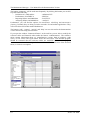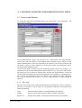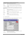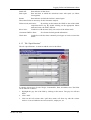
1
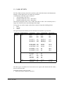
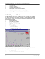
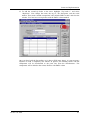
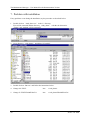
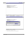
January 2001
ECN-C--01-0XX
The
MAINTENANCE MANAGER
User Manual for the
Demonstration Version
L.W.M.M. Rademakers
H. Braam
The Maintenance Manager – User Manual for the Demonstration Version
Acknowledgement
This report is part of the project entitled “Development of a Maintenance Information
System for Wind Turbines” which has been carried out in co-operation with Baas & Roost
Maintenance Consult BV. This User Manual belongs to the CD-ROM with the
demonstration version of the Maintenance Manager
The development of the demonstration version was partly financed by NOVEM, partly by
ECN and partly by Baas & Roost Maintenance Consult BV. .
ECN project number
Novem contract number
2
: 7.4087 and 7.4117
: 224.321-9957
ECN-C--01-0XX
LIST OF CONTENTS
LIST OF CONTENTS
3
1. INTRODUCTION
1.1 About the Demonstration Version
1.2 About the Manual
5
5
6
2. CASE STUDY
7
3. GETTING STARTED
3.1 Start-up
9
9
4. LOGGING FAILURE AND MAINTENANCE DATA
4.1 Screens and Buttons
4.1.1 Tab “Log”
4.1.2 Tab “Failure Data”
4.1.3 Tab “Specifications”
4.2 Alarm with Reset
4.3 Alarm with Failure
11
11
11
12
13
15
17
5. DATA ANALYSIS
5.1 General
5.2 Management of Turbine Manufacturer
5.3 Service Manager of a Region
5.4 R&D Department of Manufacturer
5.5 Final Remarks
19
19
19
22
24
25
6. DEFINING NEW TURBINES
6.1 Screens and Buttons
6.2 Copying Existing Parks and Turbines
6.3 Defining New Turbines and Parks
27
27
33
34
REFERENCES
43
ECN-C--01-0XX
3
The Maintenance Manager – User Manual for the Demonstration Version
4
ECN-C--01-0XX
1. INTRODUCTION
1.1 About the Demonstration Version
ECN and Baas & Roost Maintenance Consult (B&R) have made a demonstration version
of the Maintenance Manager. The purpose of this demonstration version is to offer
possible users of the Maintenance Manager (among others: wind turbine manufacturers,
service departments, operators, and technical managers of wind farms) the opportunity to
familiarise with the system.
The demonstration version is the result of a project entitled “Development of a
Maintenance Information System for Wind Turbines”. The project was carried out
between October 1999 and November 2000 by ECN, B&R and Lagerwey the
WindMaster. A major part of the work was sponsored by the Dutch Organisation for
Energy and Environment (Novem) in the Netherlands. Apart from this demonstration
version, the reports [17], [18], (both in Dutch) and [19] have been published within this
project. When working with the demonstration version, please note the following.
• The demonstration version of the Maintenance Manager reflects the status of the
program of November 2000. The development of the program is still ongoing and
many improvements have already been made. ECN, B&R and Lagerwey the
WindMaster are now carrying out a second project that will run until November 2002.
In this project, the system is going to be implemented at the service department of
Lagerwey the WindMaster. ECN and B&R are using the operating experience of
Lagerwey to improve the Maintenance Manager. Furthermore, ECN and B&R are
building synchronisation routines to automate data transfer from the central version of
the Maintenance Manager to the regional version and to the local version; and for data
transfer in the opposite direction.
• The demonstration version is not completely free of errors and bugs. At present, many
problems have already been solved. Some problems you have to be aware of when
working with the demonstration version are:
- The print options and the options to export the data in the “Definition Module” do
not function. These options in the analysis module however do function. This
problem is already solved in the present developments
- Some of the text is in English and some in Dutch since the original version of the
Maintenance Manager has been developed in Dutch. In the final version, the
language can be adjusted to the requirements of the customers. The default
language will be English.
- The lay out of some screens and the working of some input fields have to be
improved. This is being done in the current project, based on specific requirements
of the users. The lay-out and the input modules will become more user friendly in
the final version.
- The list with possible analysis options is only a first guess of ECN and B&R and is
definitely not complete. Based on the requirements of the users and based on the
feedback that ECN and B&R may obtain from experiences with the demonstration
version, the list can either be extended or adjusted to the needs of a specific
customer.
- It is not possible to make adjustments in the list with consumables. The list with
consumables (and also the spare parts lists) is so client specific that ECN and B&R
have decided not to implement it in the demonstration version. In the final version,
the list with consumables and spare parts will be provided in an Excel format that
can be put into the Maintenance Manager.
ECN-C--01-0XX
5
The Maintenance Manager – User Manual for the Demonstration Version
- The selection of parks and turbines in the “Analysis Module” sometimes seems not
to work properly. However, the final analyses results are correct.
- The modules for maintenance planning and scheduling which is especially of great
interest for operators do function but is in fact not appropriate for the specific wind
turbine needs. In the currently ongoing project, this part of the program is going to
be improved. It is recommended not to use these modules. Moreover, most of the
language is still Dutch.
In the demonstration version, ECN has defined some fictive turbines, parks, and failure
data. This gives you the opportunity to start immediately with the data logging module
and the data analysis module. These are the two modules that will be used most
frequently in daily practice by maintenance technicians, operators, R&D departments, and
the managers. The definition module will be used only now and than by very few users,
e.g. to adjust the FMEA data.
1.2 About the Manual
The user manual contains the following:
- A description of the turbines and parks in the demonstration version.
- Some hints to get started
- An explanation of the data logging module.
- An explanation of the analysis module.
- An explanation of the definition module.
ECN and B&R wish you success with the demonstration version of the Maintenance
Manager.
If you have any comments or suggestions, or you wish to have more information, don’t
hesitate to contact:
Luc Rademakers
ECN Wind Energy
P.O. Box 1, NL-1755 ZG Petten
Tel: +31 224 564943
Fax: +31 224 56 8214
e-mail: [email protected]
6
or: Saskia de Jager
Baas & Roost Maintenance Consult B.V.
Europalaan 526, NL-3526 KS Utrecht
Tel. +31 30 281 7823
Fax +31 30 267 01 80
[email protected]
ECN-C--01-0XX
2. CASE STUDY
ECN has filled in already some fictive turbines, parks and failure data in the Maintenance
Manager. In this chapter, the case studies are presented.
A manufacturer sells three types of turbines:
1.
750 kW turbine, IEC class 2
2.
1000 kW turbine, IEC class 1, direct drive
3.
1000 kW turbine, IEC class 2, direct drive
The turbines designed for IEC class 1 differ from those for IEC class 2 that they have a
larger rotor diameter and a somewhat higher hub height.
To keep the case studies simple, each turbine consists of only three building blocks:
1.
Rotor
2.
Nacelle
3.
Tower
The typical structural breakdown of the 1000 kW class II turbine is given below.
Turbine type
Building Blocks
Components
Tag nr.
Component ID
Specification
1000 kW-II
Rotor
Blade 1
Blade 2
Blade 3
BL1
BL2
BL3
BL28
BL28
BL28
28 m
28 m
28 m
Pitch motor 1
Pitch motor 2
Pitch motor 3
M1.1
M1.2
M1.3
PM1000_B
PM1000_B
PM1000_B
M-10
M-10
M-10
Pitching gearb 1 G2.1
Pitching gearb 2 G2.2
Pitching gearb 3 G2.3
PG1000
PG1000
PG1000
PG-10
PG-10
PG-10
Pitch bearing 1
Pitch bearing 2
Pitch bearing 3
B1.1
B1.2
B1.3
PB
PB
PB
PB-10
PB-10
PB-10
Nacelle
Generator
Pitch relay
Yaw relay
PLC
Yaw brake
Yaw motor
GEN
K1
K2
PLC
YB1
M2.1
GN1000
RE
RE
PLC
YB
YM
Direct drive
Tower
Cylindrical part
Top flange
TW
TF
CYL70
TF
H = 70 m
D=3m
The three types of turbines have been sold to two regions (WS North and WS South)
between 1990 and 1996.
WS North consists of only one park
• Park North Trend, 4 turbines 750 kW-II
ECN-C--01-0XX
7
The Maintenance Manager – User Manual for the Demonstration Version
WS South consists of four parks
• Park South Supplier
• Park South Single 1
• Park South Single 2
• Park South Start Date
8 turbines 1000 kW-I
1 turbine 750 kW-II
1 turbine 1000kW-II
6 turbines 750 kW-II
The turbines are being maintained by the two maintenance departments, one for each
region.
O&M data has been filled in only for the parks “Park North Trend” and “Park South
Supplier”.
8
ECN-C--01-0XX
3. GETTING STARTED
3.1 Start-up
User code:
Password:
DEMO
demo1
After entering the user code and the password the following screen will show up.
Furthermore, you will find “Raamwerk Demo” and “OnderhoudsManager Demo”in your
task bar.
ECN-C--01-0XX
9
The Maintenance Manager – User Manual for the Demonstration Version
The button “properties” will be used most frequently. By clicking this button you are able
to perform the following:
- Definition of a wind turbine
“definition WT”
- Performance of an FMECA
“FMECA”
- Reporting failures and O&M data
“LOG ECN”
- Analysing failures and O&M data
“Analysis”
Furthermore, you will find the options for maintenance scheduling and maintenance
planning. Presently they are being revised to meet the of wind turbine applications. They
will not be discussed in this manual furthermore.
The buttons “edit”, “reports”, “special” and “help” are not relevant for the demonstration
version and are not being discussed here.
If you open the window “Raamwerk Demo” in the task bar you are able to modify the
reference tables and financial tables under the button “Administration”. The reference
tables contain information about e.g. manufacturers, regions, kind of employee (with
costs), or root causes. The figure below shows the root causes. Note that the program
should be re-started after the reference tables are modified! Otherwise the program
continuous to work with the original reference tables. After modification of the financial
tables, a restart is not required.
10
ECN-C--01-0XX
4. LOGGING FAILURE AND MAINTENANCE DATA
4.1 Screens and Buttons
To record the failure and maintenance data select “LOG-ECN” from “Properties”. The
screen looks as follows.
For the demonstration version, only the tabs “Log”, “Failure data” and “Specifications”
will be used. (The tab “Reports” was originally used to perform various analyses. In the
current demonstration version for wind energy, the analyses can be best performed with
the option “Analysis” under “Properties”! In the final version, the tab Reports will be
used to generate standard reports.)
As soon as the failure is being noticed by either the operator, the service company, or a
technician, he can fill in the administrative data in the tab “Log”. The person who restores
the failure has to fill in the tab “Failure Data” and the tab “Specifications”. In the tab
“Failure Data” background on the failed component can be reported. In “Specifications”,
the costs (labour, consumables, parts, and others) can be reported. First the subsequent
tab’s will be explained. In Section 4.2, it will be illustrated how a failure should be
reported.
4.1.1 Tab “Log”
The tab Log is being used to report the administrative information as soon as a failure is
noticed by an operator, a service centre, or a maintenance technician. Th fields have the
following meaning:
Time:
date and time the failure is recorded (default: present time)
Melder:
Name of person who reports the failure (default: login name)
Registr. Nr.
Unique code (default: code starts with abbreviation of login name)
ECN-C--01-0XX
11
The Maintenance Manager – User Manual for the Demonstration Version
Wind Turbine:
Identification of failed turbine (combo box)
Type:
Type of event during which the failure is detected (combo box)
Alarmnr:
If a failure is detected by an alarm, the alarm code should be filled in
Energy prod:
The number of kWh’s produced by the turbine at the moment of
recording
All other fields are not relevant and obligatory for the demonstration version. However,
some of them will be discussed here. Later on, some of these fields will be used to plan
the pending actions.
Failure:
Free format to report some background information for the technician
(default value of filed "type")
Solution:
Free format to give some background information on how the failure is
repaired.
Priority:
Combo box to select if a failure has a high or low priority.
Discipline:
Combo box to select the required type of technician or external
assistance.
Status:
Combo box to report if a failure is pending, solved, etc.
Action:
Free format to report any other action to solve the problem.
4.1.2 Tab “Failure Data”
The tab “Failure Data” is being used to report the background information on the failure
in a structured manner that is suited for automated analysis afterwards.
Alarm nr.
If an alarm code is already filled in in tab “Log” the alarm code will be
generated automatically in this field.
Component:
Combo box to select the failed component
12
ECN-C--01-0XX
Logging Failure and Maintenance Data
Stand still:
Date and time of shut down
Start repair:
Date and time at which the technician starts with repair (or failure
investigation).
Restart
Date and time at which the turbine is started again.
These three fields are necessary for the downtime analysis.
Failure mode (and cause):
By clicking on the button, the FMECA data of the failed
component shows up. By double clicking on the appropriate failure
mode and cause, the field is filled in.
Root Cause:
Combo box with the most likely root causes of the failure mode
Comments FMECA Data
Work done
Free format for background information
Combo box with four most commonly used types of work to restore the
failure.
4.1.3 Tab “Specifications”
The tab “Specifications” is meant to add the costs to the failure.
It consists of four types of costs: Wages, Consumables, Parts, and Other costs. The fields
can be filled in as follows.
1. Highlight the grey bar of the field by clicking on the mouse. The grey bar will turn
black.
2. Click “Add”
3. Click on the left column and a pull down menu will show up with the various
choices. Costs are linked to the various articles, employees, etc.
ECN-C--01-0XX
13
The Maintenance Manager – User Manual for the Demonstration Version
4. Fill in the Duration (or: Amount in case of the other fields) and the program will
calculate the costs.
5. Click “Save” to save the costs.
6. All costs should be filled in in the same manner and one by one!
If the tables with employees and costs have to be changed, act as follows:
1. Go to reference table “Kind of employee” (window “Raamwerk” in the task bar!) and
add, change, or delete the desired types of employees involved. Exit and restart the
program.
2. Go to the “Financial tables” (window “Raamwerk” in the task bar, select “Financial
tables” under “Administration”).
14
ECN-C--01-0XX
Logging Failure and Maintenance Data
3. Select the appropriate type of employee, click “Change”, “Add” or “Delete” and
adjust the
- time period (field “From” and “Until”)
- “Costs per hour”
at the bottom of the sreen. Return to the screen "OnderhoudsManager".
The same procedure should be followed to adjust the “Other costs”. (Change the type of
“Other costs” in the reference tables and the costs per item in the financial tables.)
Note: The information behind the pull down menus “Parts” and “Consumables” cannot
be changed in the demonstration version. In the final version, parts lists and lists with
consumables can be put in the Maintenance Mangers in an Excel format, including
internally used codes and prices.
4.2 Alarm with Reset
Alarms that can be reset remotely occur very frequently. The related costs are the revenue
losses and the costs of the help desk employee. Here an example is how such an event
should be recorded.
1. Select the wind park in which the faulted turbine is located under “Edit”. In this case
“Park South Supplier” in the field “Actual Wind Park”. Ignore the two selection
windows and click “OK”.
2. Select “LOG ECN” under “Properties” and click “Add”
3. Select the failed wind turbine in the field “Wind Turbine”. (In this case S-Supplier1000-I-002.)
4. Select the type of event. (In this case “Alarm with reset”)
5. Fill in the alarm code or number. (In this case “12”)
ECN-C--01-0XX
15
The Maintenance Manager – User Manual for the Demonstration Version
All the other fields are not mandatory. As can be seen, the “Melder” and “Registr. Nr.”
and “Time” are generated automatically.
6. Select tab “Failure Data”. As can be seen, you do not have to fill in any details about
a component. The alarm nr. is copied from the tab “Log”
7. Fill in the data for the down time analyses. The fields to be filled in for the FMECA
properties depends on the "Failure type". In case of "alarm with reset", no additional
information is required. The type of work is in this case default “Reset” but can be
adjusted if necessary.
8. Click “Save” and select tab “Specifications”. Please note that there is only one type
of costs to be filled in: “Wages”.
16
ECN-C--01-0XX
Logging Failure and Maintenance Data
9. Select the help desk employee and fill in the number of hours. (If the help desk
employee is not present in the selection options, try to add the employee in the
reference tables and in the financial tables. Don't forget to restart the program after
modification of the reference table(s). The procedure is described in Section 4.1.3).
Click “Save”
4.3 Alarm with Failure
In this case, an alarm is generated by the turbine. The Help desk employee (logged in as
DEMO) reports the failure to the Sr technician who has to travel 2 hours and carry out the
repair for 3 hours. (The Sr technician is logged in as ECN).
1. Select the wind park and turbine as demonstrated in Section 4.2, step 1, 2, 3, and 4
and select event “Failure with alarm”. Fill in alarm nr. 13.
ECN-C--01-0XX
17
The Maintenance Manager – User Manual for the Demonstration Version
It appears that the help desk employee is not able to reset the turbine. He informs the Sr.
Technician and gives him the alarm nr. (13) and the Registr. nr. (DEMO319). He saves
the data and fills in the time he spent in tab “Specifications”.
The Sr. Technician carries out the repair and fills in the tab “Log” identical to the help
desk employee. He has to change the registration number manually.
2. Select tab “Failure data” and fill in the data (In this case a failed pitch motor).
3. Click “Save” and select tab “Specifications”. Fill in the appropriate data and close the
window.
18
ECN-C--01-0XX
5. DATA ANALYSIS
5.1 General
The operation of the analysis module can be best demonstrated by means of the case
studies. ECN has filled the demonstration version already with some fictive O&M data.
ECN did not fill in data for all parks so sometimes you will find zero maintenance actions
or downtimes which is correct. The same holds for the maintenance costs. Only in some
cases the maintenance costs have been filled in. The data will be analysed from different
persons with different point of views.
Please feel free to try all the other options too but take into account that no failure data is
recorded for some turbines.
5.2 Management of Turbine Manufacturer
Situation 1: The management wants to compare the “O&M performances” of region WS
North with that of WS South. for the WS 750 kW-II turbines (Note that no data is
available in region WS South. You may fill in some data in the Log-module yourself for
these turbines in 1998.)
i
ii
The number of failures per region (per turbine)
The downtimes (logistics and repair) per region
Carry out the following steps
1.
Properties Æ Analysis
2.
Type of WT: “WS 750 kW-II”
3.
Regions : All (= Workshop North, Workshop South) Æ next
4.
All available data in 01/01/1998 – 31/12/1998
ECN-C--01-0XX
19
The Maintenance Manager – User Manual for the Demonstration Version
5.
RankingÆ next
6.
RegioÆ next
20
ECN-C--01-0XX
Data Analysis
7.
i Number of maintenance actions
8.
Next
ECN-C--01-0XX
21
The Maintenance Manager – User Manual for the Demonstration Version
9.
ii Æback, downtimeÆ next
10.
Close
5.3 Service Manager of a Region
Situation 2: The region manager of WS South wants the O&M performance of the first
two operational tears of the WS 1000 kW class I turbine.
i
Number of failures per turbine
ii
Downtime per turbines
iii
Maintenance costs per turbine
1.
Properties Æ Analysis
2.
Type of WT: WS 1000 kW-I
3.
Regions : Workshop South
4.
Wind Parks : Park South Supplier
5.
WT : All Æ next
6.
All data between 0 en 17500 working hours
7.
RankingÆ next
8.
WindturbineÆ next
9.
i Number of maintenance actionsÆ next
10.
ii Æback, downtimeÆ next
11.
iii Æback, maintenance costs
12.
You may try the other options too!
13.
Close
22
ECN-C--01-0XX
Data Analysis
Situation 3: The manager of region WS South also wants to know how often “lightning”
is the root cause for events in “Park South Supplier”
1.
Properties Æ Analysis
2.
Type of WT: WS 1000 kW-I
3.
Regions : Workshop South
4.
Wind Parks : Park South Supplier
5.
WT : All Æ next
6.
All available data
7.
Component dataÆ next
8.
Componets : all
9.
Root cause – number of occurances Æ next
10.
Close
Situation 4: The manager of region WS South wants to identify the most vulnerable
i
building blocks
ii
components
in “Park South Supplier”
1.
2.
3.
4.
5.
6.
7.
8.
9.
10.
11.
12.
13.
14.
15.
Properties Æ Analysis
Type of WT: WS 1000 kW-I
Regions : Workshop South
Wind Parks : Park South Supplier
WT : All Æ next
All available data
RankingÆ next
i Building block Æ next
Number of maintenance action Æ next
BackÆdowntimeÆnext
ii Æ back Æback group of components
all Æ next
Number of maintenance action Æ next
BackÆdowntimeÆnext
Close
Situation 5: The manager of region South wants detailed information about the pitch
motors in “Park South Supplier”
i
failure modes
ii
failure causes
iii
suppliers
1.
2.
3.
4.
5.
ECN-C--01-0XX
Properties Æ Analysis
Type of WT: WS 1000 kW-I
Regions : Workshop South
Wind Parks : Park South Supplier
WT : All Æ next
23
The Maintenance Manager – User Manual for the Demonstration Version
6.
7.
8.
9.
10.
11.
12.
All available data
Component dataÆ next
Componnets : Pitch motor 1, 2, 3
Failure mode – number of occurances Æ next
Æ back, Failure cause – number of occurances Æ next
Æ back, supplier – fraction of maintenace actions Æ next
Close
5.4 R&D Department of Manufacturer
The R&D department wants to know the MTTF (Mean Time To Failure) for a yaw brake
of a 750 kW class II turbine. Note that the MTTF data is only relevant for estimating the
failure rate of new designs if it is constant over the time. This means that first a trend
analysis should be performed.
1.
Properties Æ Analysis
2.
Type of WT: WS 750 kW-II
3.
Regions : Workshop North
4.
Wind Parks : Park North Trend
5.
WT : All Æ next
6.
i All available data
7.
Trend analyseÆ next
8.
components: yaw brake Æ next
(Note that the curve of the failure intensity is constant in between say 14.000 and 66.000
hrs. of operation, which corresponds to approximately 1,6 and 7,5 years.
9.
10.
24
ii Æback, Æback,
all availbale data between 12000 and 87000
ECN-C--01-0XX
Data Analysis
11.
12.
statistical analysisÆ next
components, yaw brake Æ next
13.
Close
5.5 Final Remarks
The following remarks should be made to better interpret the analysis results.
•
The number of maintenance actions means the number of actions for which the
technician had to go to the turbine. The failure could not be solved by a reset from the
helpdesk.
•
The difference between “failure rate” and “failure intensity” requires some
understanding of the theory on reliability and safety analyses. It is beyond the scope of
this report to go into more detail.
•
All the results are “normalised” to [per turbine] in order to compare the O&M
performances independent from the size of the population of a region or park.
•
If you go from a certain screen back to the previous on by clicking “Back”, you will
notice that the button “Next” is disabled. You are obliged to make your selection
again. This is done to avoid errors by clicking too fast through the various screens.
ECN-C--01-0XX
25
The Maintenance Manager – User Manual for the Demonstration Version
26
ECN-C--01-0XX
6. DEFINING NEW TURBINES
6.1 Screens and Buttons
To define new turbines, open the option “Definition WT” under “Properties”. The screen
below will show up.
To define each turbine in a unique manner it is necessary to define the:
- Wind park
- Wind turbine
- Building blocks (or main system) of each turbine
- Components of each building block
These items correspond with the “tab’s” of the definition screen. The tab “Sub-comp.” is
not being used in this demonstration version. The tab “Comp. Data” can be used to define
spare parts and the tab “Consum.” to define consumables.
As already stated in the introduction, Chapter 1, three types of turbines are already
defined in the Maintenance Manager. To see what information is attached to the wind
park “Park South Supplier”, you should click on the park and than on the button
“Change”. The screen on the following page will show up.
ECN-C--01-0XX
27
The Maintenance Manager – User Manual for the Demonstration Version
The items Region, Terrain, Wind Conditions, Owner, Operator, and Service Centre work
as combo boxes. The options to choose can partly be set in the corresponding reference
tables (See chapter 2). Terrain and wind condition options are standard and cannot be
changed.
By clicking the tab “wind turbine” you can see that the wind park “Park South Supplier”
consists of 8 times 1MW class 1 turbines.
28
ECN-C--01-0XX
Status and Implementation
With the button “Change” you can change the background information of the turbines,
e.g. the date the turbine is taken in operation, or you can add some unique characteristics
to the turbine (rotor diameter, special feautures, rated power, etc.)
ECN-C--01-0XX
29
The Maintenance Manager – User Manual for the Demonstration Version
Each turbine in this demonstration version consists of three building blocks: rotor, nacelle
and tower. This can be seen by clicking on tab “Building Block”.
By “Change” you can change for instance the supplier of a main system or the
configuration identification.
30
ECN-C--01-0XX
Status and Implementation
Each building block consists of various components. E.g. the rotor consists of three
blades, three pitch motors, etc. A complete list can be found under tab “Component” .
Each component is defined uniquely by its tag nr. So “Pitch motor 1” corresponds to
pitch motor 1 on the electrical schematics. (The “component level” is also the level at
which the FMEA is being performed and at which data should be recorded for further
analysis. This will be discussed later on.)
By “Change” it is possible to change o.a. the following:
- Name, tag nr, description, etc.
ECN-C--01-0XX
31
The Maintenance Manager – User Manual for the Demonstration Version
-
Type and object are two fields that can be used to make various cross-sections
through the database. E.g. you can select all electrical motors during the analysis
if you add the option “electrical motor” to the component. Or all electrical
equipment can be compared with hydraulic equipment. The possibilities for type
and object can be defined in the reference tables (type of object and type of
component).
The field “Component ID” is meant to select the ID from the spare parts list or from the
stock. In the case of the pitch motor, you can use a pitch motor from supplier A (PM
1000_A) or B (PM 1000_A). You can select the data in two ways: the full name (1000
kW pitch motor, left hand field) or the code (PM 1000_A, right hand field). The list with
component ID’s and their codes is defined under tab “Comp. Dat.”
32
ECN-C--01-0XX
Status and Implementation
Note: The list with components will be tailor made for each individual customer. The
customer should provide the data in a digital format. Since this is not the case in this
demonstration version, the option does presently not work properly and will be improved.
Furthermore, you can define the serial number of a component. In practice, this will only
be done for major components, not for smaller components.
6.2 Copying Existing Parks and Turbines
To define a new park with existing turbines you should carry out the following steps.
1.
Properties Æ Definition Windturbine
2.
Select Tab “Wind Park”
3.
Push button “Add” and fill in the data (in our example it is called ECN-test-1)
4.
Close the window by “OK” and notice that the park is added to the 5 other parks
5.
Go to park “Park South Single 2” (this consists of the 1 MW class 2 turbines)
6.
Go to tab “Wind Turbine” and select the turbine S-Single-2-1000-II.
7.
Select “Duplicate”
ECN-C--01-0XX
33
The Maintenance Manager – User Manual for the Demonstration Version
8.
Modify the name, date in use, etc.
9.
Select the park in the combo box (in this case ECN-test-1)
10.
Mark “Secties, onderdelen en componenten overnemen” to make sure that all
components and building blocks are being copied
11.
Mark “FMECA-gegevens overnemen” to make sure that the FMECA data of each
component is being copied.
12.
Select “OK”
Now select tab “Wind Park” , go to ECN-test-1, go to tab “Wind Turbine” and see that
the turbine is being copied. If you go to the building blocks and components you will see
that all data is being copied. You now only have to modify the serial numbers for the
main components if you want to ensure configuration control.
6.3 Defining New Turbines and Parks
Here an example is given how to define a new turbine, which consists of only one
component, the tip brake. The turbine is called “Turbine tip brake” Adding more
components to the turbine means repeating the same action or copying existing data.
To define a new turbine you should do the following.
1. Select the reference table “Main Libraries” in “Raamwerk Demo”
2. Select “Add” and type the new name of the library (In this case “ECN-tip brake”)
3. Follow the same procedure to define a new type of wind turbine. Add “ECN tip brake
demo” to the reference table “type of wind turbines”
4. Select “Save” and restart the program to update the reference tables
34
ECN-C--01-0XX
Status and Implementation
5. Select “FMECA” from “Properties”
6. Select the “ECN-tip brake” library as shown below.
7. Select tab “FM-bibliotheek” and select “Toevoegen” (which is Dutch for Add!)
8. Fill in the name of the component (Tip brake) and close the window
9. Double click on “tip brake”
ECN-C--01-0XX
35
The Maintenance Manager – User Manual for the Demonstration Version
10. The FMEA sheet will show up
11. Select the right mouse button and select “Toevoegen faalvorm” (Adding failure
mode)
12. Fill in as much failure modes and causes as necessary (The last 5 columns are not
being used in this demonstration version.) and close the FMECA screen by “Sluiten”.
36
ECN-C--01-0XX
Status and Implementation
13. Select “Definition WT”,
14. Select tab “Wind Park” and select park “ECN-test 1
15. Select tab “Wind Turbine”
16. Select “Add”
17. Fill in all turbine data as shown below. Select “ECN-tip brake demo” as type of
turbine.
18. Click OK to return to the definition screen. You will notice that there are two turbines
in park ECN-test–1.
ECN-C--01-0XX
37
The Maintenance Manager – User Manual for the Demonstration Version
19. Select tab “building block” and select “add”
20. Fill in an appropriate name, select the supplier and the configuration ID and click
OK. You will notice that the turbine “Turbine tip brake” now consists of one building
block.
21. Select tab “component” and select “add”
22. Fill in the data as shown below. Since there are two tip brakes, this one is called Tip
brake 1. To add the FMECA data to the component select “ECN-tip brake” from the
library reference and “Tip brake” from the parts in this library. (“Component ID” is
not obligatory.) Then select OK and notice that the building block “Rotor” has one tip
brake.
38
ECN-C--01-0XX
Status and Implementation
23. To add the second tip brake to the rotor: highlight “Tip brake 1” and select
“Duplicate”. Now change the name, the tag nr., the description, and the serial
number. Then, mark “include components” and “include FMECA-data” and close the
window. You now have two tip brakes with the FMECA data attached.
Once you have built the first turbine (as is done at ECN many times), it is not necessary
anymore to build a completely new turbine. In practice, the building blocks with the
components will be downloaded as the parts lists from the manufacturers. The
components will be linked to the various libraries with FMECA data.
ECN-C--01-0XX
39
The Maintenance Manager – User Manual for the Demonstration Version
7. Problem with installation
If any problems occur during the installation, try the procedure as described below:
1. Double click on “Onh_demo.exe” in the C:\ directory.
Files will be extracted and the directory “Onh_demo” with the sub directories
“Frame” and “Onhmn” will be generated.
2. Go to directory “Onh_demo” and delete “P_bnr.dbf”
3. Double click on “Bnr.exe” and follow the instructions below
4. Change: M:\TEST\
into
c:\onh_demo\
5. Change: P:\TEST\FRAME\DATA\
into
c:\onh_demo\FRAME\DATA\
40
ECN-C--01-0XX
Status and Implementation
6. Change
G:\UITLEVER\DEMO1\
in all fields into
c:\
Note: The directory C:\Temp must be created.
7. Close the window and fill in the user name and password
ECN-C--01-0XX
41
REFERENCES
[1]
Rademakers, L.W.M.M. et al., "Methodology for Probabilistic Safety Assessments of
Wind Turbines -Demonstrated by a Case Study of the Lagerwey LW 15/75 Design",
ECN-C--93-010, Petten, The Netherlands, March 1993.
[2]
Rademakers, L.W.M.M. et al., "Reliability Analysis and Design Review of the
NEWECS-45; Part 1: Feedback of Operational Experience", ECN-C--94-066,
Petten, The Netherlands, September 1994.
[3]
de Smet, B.J., Rademakers, L.W.M.M., en Goezinne F., “Betrouwbaarheidsanalyse
NedWind 40”, ECN-C--96-051, Petten, november 1996.
[4]
Rademakers, L.W.M.M. en Van Hulle, F.J.L: “Veiligheidsanalyse van de HMZ 1
MW windturbine”, ECN-C—93-077, Petten, december 1993.
[5]
Rademakers, L.W.M.M. et al., "Reliability Analysis of the AOC 15/50 Wind Turbine
Generator”, ECN-C--94-057, november 1994.
[6]
Rademakers, L.W.M.M. et al.: European Wind Turbine Standards I, Chapter 3:
“Assessment of Wind Turbine Safety; Recommended Practices”, EUR 16898 EN,
1996.
[7]
Rademakers, L.W.M.M. et al.: European Wind Turbine Standards I, Chapter 4:
“Assessment of Wind Turbine Safety; Case Study”, EUR 16898 EN, 1996.
[8]
Braam, H. et al.: European Wind Turbine Standards II, Chapter 2: “Quantification of
Failure Probabilities”, ECN-C--99-073, June 1998.
[9]
B. de Smet en L. Rademakers: "De Opzet van een Windturbine Database:
Verzamelen en Analyseren van Faal- en Onderhoudsgegevens", concept memo,
november 1994, ECN.
[10] C. Latijnhouwers: "Data Collection and Analysis for Wind Turbines: Preview for
Developing a Database", ECN-DE Memo-95-25, Mei 1995.
[11] R. Smit: "Database Applicatie: Database voor het Analyseren en Demonstreren van
Windturbinegegevens", Hoge School van Amsterdam, Maart 1996.
[12] Verschuren P.J.R. en Wilms, E.F.: "Storingsregistratiesystemen: een Onderzoek
naar Factoren van Invloed", Afstudeerversslag Koninklijk Instituut voor de
Marine, Augustus 1994.
[13] H. Lammerse: "Bedrijfszekerheidsgegevens: Verzamelen, Evalueren, Presenteren",
Nederlandse Vereniging voor Bedrijfszekerheidstechnologie, Kluwer 1993
[14] S.J. Smeulders: "AEGIR, een Systeem om Storingsgegevens Gestructureerd te
Verzamelen en Analyseren", In opdracht van AKZO Engineering B.V., Januari 1992
[15] Rehfeldt,
K.:
“Untersuchungen
der
Aktuellen
Kostensituation
der
Windenergienutzung in Deutschland”, paper presented at DEWEK 2000, 7-8 June
2000, page 32-36.
ECN-C--01-0XX
43
The Maintenance Manager – User Manual for the Demonstration Version
[16] ISET: “Wissenschaftliches Mess- und Evaluierungspragramm (WMEP zum
Breitentest 250 MW Wind”, Jahresauswertung 1998 and Jahresauswertung 19992000.
[17] Braam, H. and Rademakers, L.W.M.M.: “Informatiesysteem voor Windturbinestoringen - Specificaties”, ECN-CX--00-097, December 2000
[18] de Jager, S. and Rademakers, L.W.M.M.: “De Toepasbaarheid van de
Maintenance Optimizer voor Windenergie”; Baas&Roost Maintenance
Optimisation BV, Doc. nr. ECN 000800
[19] Rademakers, L.W.M.M. and Braam, H: “The Maintenance Manager - Collecting
and Analysing Maintenance Data of Wind Turbines”, ECN-C--01-012, January
2001
44
ECN-C--01-0XX
ECN-C--01-0XX
45
The Maintenance Manager – User Manual for the Demonstration Version
Date: 15-1-2001
Report number:
ECN-C--01-0XX
The Maintenance Manager - Collecting and Analysing Maintenance Data
of Wind Turbines
Title
Author(s)
L.W.M.M. Rademakers, H. Braam
Principal(s)
NOVEM, ECN
ECN project number
Order number
7.4087 and 7.4117
224.321-9957
Programme(s)
TWIN
Abstract
ECN and Baas & Roost Maintenance Consult (B&R) have made a demonstration version of the
Maintenance Manager. The purpose of this demonstration version is to offer possible users of the
Maintenance Manager (among others: wind turbine manufacturers, service departments, operators,
and technical managers of wind farms) the opportunity to familiarise with the system.
The demonstration version is the result of a project entitled “Development of a Maintenance
Information System for Wind Turbines”. The project was carried out between October 1999 and
November 2000 by ECN, B&R and Lagerwey the WindMaster. The demonstration version of the
Maintenance Manager reflects the status of the program of November 2000. The development of
the program is still ongoing and many improvements have already been made.
This report contains the User Manual for the demonstration version of the Maintenance Manager.
Key words
Wind energy, Reliability, Maintenance, Availability
Authorization
Name
Author
L.W.M.M. Rademakers
29-5-2001
Checked
T.W. Verbruggen
?? 2001
Authorized
H.J.M. Beurskens
?? --2001
46
Signature
Date
ECN-C--01-0XX