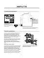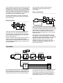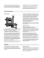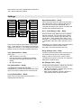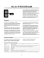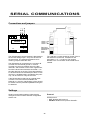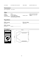
1
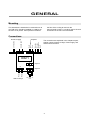
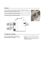
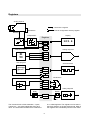
User manual 28.9.2007 V1.1 6803 Thermocouple monitor and transmitter INTRODUCTION 6803 is a rail-mounted two-channel thermocouple measurement unit that is capable to measure the thermocouple resistance in order to rectify its condition. The input channels are individual and can be used for different signals. The unit has two analog outputs or alternatively one analog and one serial output. The serial output accepts Nokeval SCL and Modbus RTU commands. Up to four logical alarms can control two alarm relays. The inputs are galvanically isolated from the outputs and the supply voltage, but not from each other. There is four built-in inter-channel functions: average, difference, minimum, and maximum. More mathematical and conditional operations may be realized with a simple programming language called ELo. The front panel has a four-digit display and four pushbuttons that can be used to monitor the readings and to change the settings. The settings can also be edited on a personal computer using the RS-485 serial connection. The ELo program can be edited on a personal computer only, not on the front panel. How to use this manual The transmitter consists of several quite independent blocks like the two inputs, analog outputs, serial communications and so on. That is why this manual is also divided in chapters, one chapter concerning one block. First read through the chapter ”General” to find out how to mount the transmitter and to open the transmitter case etc and how to get started with the configuration settings, either with the front panel or with a PC software. Then advance to the chapter ”Power supply”. To get the transmitter to measure something, read the chapter ”Inputs”. To get an analog output, read the chapter ”Analog output”, and so on. Table of contents Introduction.........................................................................................................................................................2 General...............................................................................................................................................................3 Power supply.......................................................................................................................................................7 Front panel..........................................................................................................................................................8 Inputs................................................................................................................................................................11 Analog outputs..................................................................................................................................................16 Alarms and relays.............................................................................................................................................18 ELo program.....................................................................................................................................................20 Serial communications......................................................................................................................................22 Specifications....................................................................................................................................................26 Manufacturer Tel +358 3 3424800 Fax +358 3 3422066 WWW: www.nokeval.com Nokeval Oy Yrittäjäkatu 12 FIN-37100 Nokia Finland 2 GENERAL Mounting This transmitter is intended to be mounted on a 35 mm DIN rail. It should be installed on a wall as on the front cover picture. Other positions will affect the flow of the cooling air and ruin the thermocouple accuracy. A small air gap to the next instrument on the rail is recommended. Connections D0 (B-) D1 (A+) Common Out1 4 3 2 1 A Out2 Out Common Out1 24 VDC/AC 4 3 2 1 A Outputs 85-230 VAC Power supply 4 3 2 1 B 4 3 2 1 B The connectios are explained in the chapters Inputs, Analog outputs, Alarms & relays, Power supply, and Serial communications. 6821 Relay 2 Relay 1 G 1 2 3 4 Alarm relays F 1 2 3 4 Input 1 H 1 2 3 4 Input 2 RTD + TC, mV, V, mA 3 Jumpers To access the jumpers, use a small screwdriver to click the four locks (see photo). Then pull the top and bottom parts of the case apart. The power supply must be disconnected to avoid electric shocks. The picture shows the jumper locations and the default setup. Jumpers labeled ”Free” can be taken off and used where needed. See Analog outputs Out1 = mA Out1 = V Out2 = mA Out2 = V Out2 = 485 See Serial comms The jumper positions are explained in the chapters Analog outputs and Serial communications, pages 16 and 22 respectively. Don't use 485 floating 485 term Free Free Free Don't use Don't use Don't use Don't use Configuration settings There is a plenty of settings, that are used to define the operation of the inputs, the outputs, etc. There is two ways to access them: • On the front panel, see chapter Front panel, page 8. • Using a PC and a serial communications, see chapter Serial communications, section PC configuration, page 22. 4 Registers Analog input x2 = writes into a register Resistance = can be configured to read any register Reading Lowpass filter Display Registers Scaling 123.4 In1 In2 Res1 Res2 Built-in functions Analog output x2 Avg Min Max Diff Avg Min Max Diff User program Serial interface F1 F2 F3 @18+=@1 @2>0?2 F12 OR function Alarm comparator x4 Alm1 Alm2 Alm3 Alm4 + - Relay output x2 Delay NO/NC Rel1 Rel2 A1 indicator The function blocks of this transmitter – inputs, outputs, etc – are quite independent from each other. The information between them is delivered in so called registers. The registers can be seen in the block diagram on the gray background. Most of the registers are controlled by some function block. 5 For example, the register ”In1” is controlled by the first input – there is the input 1 reading. to read the register In1 or any register. The symbol represents this in the block diagram. Registers F1-F12 are controlled by the user program written in ELo language. The register values can be viewed with a monitor function, either on the front panel or the PC configuration program Mekuwin. Any register can be used as a ”source” for another block. For example, the analog output 1 can be set Register 1 2 3 4 5 6 7 8 9 10 11 12 13 14 15 16 17 18 19 20 21 22 23 24 25 26 27 28 29 30 31 32 33 Name In1 In2 Res1 Res2 Avg Min Max Diff RA1 RA2 CJ Cycle Out1 Out2 Alm1 Alm2 Alm3 Alm4 Rel1 Rel2 F1 F2 F3 F4 F5 F6 F7 F8 F9 F10 F11 F12 Keys Explanation Input 1 scaled reading °C/°F/mV Input 2 scaled reading Input 1 resistance kohm Input 2 resistance Average of the readings, (In1+In2)/2 Smaller of the readings In1, In2 Greater of the readings Difference In1-In2 Resistance alarm 1 state (0=passive, 1=active) Resistance alarm 2 state Internal cold junction temperature in °C The measured time to get all the channels, in seconds Analog output 1 signal in mA or V Analog output 2 signal in mA or V Logical alarm 1 state (0=passive, 1=active) Logical alarm 2 state (0=passive, 1=active) Logical alarm 3 state (0=passive, 1=active) Logical alarm 4 state (0=passive, 1=active) Relay 1 state (0=passive, 1=active) Relay 2 state (0=passive, 1=active) Free floating point register for ELo programs Free floating point register Free floating point register Free floating point register Free floating point register Free floating point register Free floating point register Free floating point register Free floating point register Free floating point register Free floating point register Free floating point register Front panel key state, see below Keys register Keys register gives a sum of the codes of the keys currently pressed: Key Code ^ 2 v 4 * 8 > 16 6 POWER SUPPLY The transmitter 6803 is available for two supply voltage ranges, that are nominally called ”24VDC” and ”230VAC”. 6803-230VAC This model accepts supply voltage of 85 to 260 V DC or AC. The supply is connected in connector A terminals 1 and 3. 6803-24VDC This model accepts supply voltage of 20 to 28 V DC or AC. The supply is connected in connector A terminals 1 and 2. Either polarity will do. 24 V 0V This transmitter will consume less than 200 mA. However at power-up it will need 500 mA. 4 3 2 1 A 4 3 2 1 B G 1 2 3 4 F 1 2 3 4 H 1 2 3 4 0V 230 V This unit has an internal pre-fuse. If an external one is used, it should be at least 500 mA T. 4 3 2 1 A 4 3 2 1 B G 1 2 3 4 F 1 2 3 4 H 1 2 3 4 6821 6821 7 FRONT PANEL Conf A1 A2 * Nokeval Configuration state The front panel can be used to monitor the operation of Alarm indicators the transmitter and to change the settings. It has several states of operation: • Normal state – displaying the readings. • Configuration state – changing the settings. • Monitor state – displaying the readings and other Select variable data. Enter Exit 6800 Series Normal state After power-up, the front panel is in the normal state, displaying the input 1 reading (unless otherwise set). The ”channel” being displayed can be selected using the ^v keys. While changing the channel, the channel name is displayed until the key is released. Which channels can be selected, depends on the settings. The > key can be used to access and change the value of pre-selected registers in order to control the ELo program. A1 and A2 indicate the states of the alarm relays. They are lit if any of the alarms selected for the relay is active. The relay NO/NC setting does not affect the alarm indicators. Configuration state Most data types are edited simply with ^v keys, finally exiting with * key. Entering Press the * and ^ keys simultaneously two seconds in the normal state to enter the configuration state. When entered, the Conf led will light. If configuration password is set, you will need to enter it now (Cod.0 displayed). In case the password is not known, switch the power off, hold the * and > keys pressed and switch the power on again – ”PWDC” is displayed briefly. This will also set the serial settings to their default values. Floating point values, such as scaling and the lopass filter, are edited with ^v> keys: select digit to edit (blinking) with > and change it with ^v. When the decimal point is blinking, it can be moved with ^v. The first digit can be replaced with a minus sign. A password is set as follows: push ^ to select Set (means password will be used), then push > to enter the new password. Cod.0 is shown. The password is a sequence of six keypresses using all the four keys. Enter the same password twice; if they match, Set is shown again and you can exit with *. If they didn’t match, Off is shown. Redo from start. To disable a password, push v to select Off and exit with *. Navigating The menu is organizated hierarchically. You can move within one menu using the ^v keys and enter a submenu with the > key. Returning from a submenu is done with the * key. See the menu chart on page 10. The math program can not be edited with the front panel. An RS-485 connection to a PC is needed. Editing To see or edit a setting value, press > key. 8 shown: Save to keep the settings made, and Undo, to discard all changes. Select ^v Save or Undo and push >. Exiting When all settings are done, exit from the configuration menu with * key. Two options are Monitor state Monitoring can be used to examine the internal readings, called registers. The built-in monitoring is started by pressing * and v together. Select the item using ^v keys, and finally exit with *. There are three possible diagnostic messages: Sensor Fault: some channel has improper connection, overranging, or a broken sensor or wires. AD Error: A/D converter is not working. Needs service. Math Error: there is an error in the math program. The registers are explained on the page 6. The last item is Diag, that can be used to see diagnostic messages. Push >. If nothing happens, then there are no messages. If happens, try ^v to see if there are several messages. Exit with *. Settings Conf General Display Inputs Math Outputs General CfCode Display Src1 Dec1 Ed1 In the configuration settings menu, there is two submenus concerning the front panel: General, and Display. need four registers, set the rest to Off. After powerup, the register selected in Src1 is displayed, and the rest can be viewed using the ^v keys. Dec1…Dec4 (Display) Defines how many digits after the decimal point is displayed on the registers defined in Src1…Src4. Can be set between -2 and 3. Negative values mean, that the corresponding number of last digits is rounded to zero. Examples with a reading of 12.34: • Dec=2: ”12.34” • Dec=1: ”12.3” • Dec=0: ”12” • Dec=-1: ”10” (rounded to nearest 10) Alarms Relays Serial Src4 Dec4 Ed4 CfCode (General) Ed1…Ed4 (Display) This defines a password for the settings. If this is set, the settings can't be accessed without knowing the password. If register selected in Src1 is Src1 > Ed1 being displayed, and the user ^ Src2 > Ed2 pushes the > key, then the v register selected in Ed1 is > Src3 Ed3 displayed and its value can be > changed. Likewise while Src2 is Src4 Ed4 displayed, the register selected in Ed2 can be edited. This way the user can change register values manually and affect the ELo program operation or control an analog output manually. * To change the password on the front panel, go to the CfCode setting and push > to edit the value. Options Off and Set are shown; select Set with the ^v keys. Then push >, and Cod.0 should be displayed. Now enter six keypresses using any of the four keys. Then enter the same sequence another time. If they matched, Set is displayed again and you can exit with *. Otherwise Off is displayed. Src1…Src4 (Display) Other registers than F1…F12 should not be selected in Ed. If this operation is not desired, set the Ed registers to Off. Display submenu is used to define, what readings (or registers) you want to see on the display. Up to four registers can be selected in Src1..Src4 (registers are described on page 6). If you do not When a register value is changed this way, it is stored in the non-volatile EEPROM memory and restored when this transmitter is powered up next time. 9 Menu tree The complete configuration menu is shown here to aid navigating. The menus are explained in the relevant chapters: • General and Display: page 9. • • • • • Inputs: page 13. Math: page 20. Outputs: page 16. Alarms and Relays: page 19. Serial: page 22. Display Src1 Dec1 Inputs Ed1 In1 Dec2 In2 Ed2 Src3 General Dec3 CfCode Ed3 Src4 Dec4 Conf In1 Unit MaxRes Differential Lopass Setuptime Pts ResInterval Mea1 Recovery Sca1 AlmDelay Sca2 Display Inputs Math Math ELo Outputs Outputs Alarms Alarms Relays Out1 Out1 Out2 Src Alm1 Serial Range Alm2 Rdg1 Alm1 Alm3 Type Alm4 Src Relays Level Rel1 Rel1 Rel2 Src1 Hyst Src2 Serial Src3 Protocol Src4 Address Delay Baud NC Dec 10 Speed Sensor Mea2 Ed4 General Common Common Src2 Out1 Rdg2 Out2 Break INPUTS Connections and jumpers 4 3 2 1 A 4 3 2 1 B G 1 2 3 4 F 1 2 3 4 H 1 2 3 4 6821 Free In1 = mA In2 = mA In2 pin1 = 4w In2 pin1 = +15V Keep these open Input signals are connected in connectors F and H: F is the input 1 and H is the input 2. 1 2 3 4 Free Free + Connect the positive wire of the thermocouple in terminal 2, and the negative in terminal 3. Tc Potential equalization The input circuitry is galvanically isolated from the power supply and output circuits. However the input channels are not isolated from each other. Moreover there is a differential amplifier in the inputs, that requires that the potential on the inputs (terminals 2 and 3) is near the input circuitry ground (terminal 4). 1 2 3 4 With RTD's the differential amplifier input is tied to the input ground via the sensor connections and there is no matter. With other inputs, the differential amplifier inputs must be tied to the internal ground somehow. There is three different ways: 1 2 3 4 In1 + - In2 Diff. amp + x - + Gnd sw Input gnd Internal grounding switch This switch will pull the input circuitry ground potential to the negative line potential on the channel being measured. The input terminals 2 and 3 are connected through semiconductor switches to the differential amplifier feeding the analog-to-digital converter. The other channel is separated by open semiconductor switches. In the picture there is a thermocouple on both channels as an example. There is no external connection to the terminal 4, the input ground. The internal grounding switch is enabled by setting Differential to No in the Inputs / Common menu. 11 The potential of the other input can be several volts different than this channel, since it is separated by the switches. However the switches will not tolerate infinitely voltage. The rule is, that the both lines (+ and -) of an input must be within 10 V in respect to the negative line of the other input. A difference of more than 30 V may damage the inputs. This connection method will give the best performance against disturbances and overvoltages. Other external path This is the easiest way to connect, and the only that will allow several volts between the negative lines of the inputs. 1 2 3 4 External linking Link 1 2 3 4 + - Diff. amp + x - + - Gnd sw Diff. amp + x - The potential equalization does not have to be a link on the terminals – it can be a longer path as far as it keeps the potential between terminals 3 and 4 small enough. If an external path exists, then it is best to open the internal grounding switch by setting the Differential setting to On in the Inputs / Common menu. Gnd sw If the input sensors are galvanically isolated from each other, then it is recommended to tie them both to the input circuitry ground. Connect a piece of wire between the terminals 3 and 4. This ties them to each other too. An example of this could be two thermocouples mounted on the same metal object. In this case, the negative wires are not allowed to be connected together at the transmitter terminals. The link between terminals 3 and 4 can not be used. Instead, have the link on the other input only – it will keep the differential amplifier inputs near ground on both inputs. It does not matter if the internal grounding switch is open or closed, since the differential amplifier negative input is externally tied to the input ground. So the Differential setting in Inputs / Common can be in any position. Operation Isens CJ A/Dconverter Sensorprocessing Scaling Lowpass filter In1 In2 Built-in functions Avg Min Max Diff Avg Min Max Diff Several analogue switches are used to connect the A/D converter and the sensor current supplies to the channel being measured. In addition to the two external channels, there is two internal channels: the cold junction temperature (for thermocouples) and the RTD excitation current measurement. The result is processed according to the sensor type selected. For the temperature sensors, a temperature reading in °C or °F is obtained; for 12 other input types, a mV reading is obtained, for example. This transmitter provides a possibility for a free two-point scaling. It can be used to cancel sensor errors or to convert the input signal to the ”engineering units”. A first-order lowpass filter can be applied to remove noise and disturbances. This transmitter calculates always four interchannel readings: the average, the smaller, the greater, and the difference of the inputs. Sensor resistance capacitance of dozens of nanofarads, so some actions are needed before a normal measurement can be taken. First, 6803 short-circuits the sensor using approx 2 kilo-ohms for 20 milliseconds to remove the charge. Secondly, when the next normal measurement is taken, the sensor is connected to the A/D converter using the analog switches and then a longer than normal recovery time is waited before starting the A/D conversion. This time is user-selectable, see Inputs/Common/Recovery. How it works +15V 1 2 3 4 1 2 3 4 In1 10Mohm + - In2 The measured resistance is available in registers Res1 and Res2 for ELo program, alarms, display, or serial reading. Diff. amp + x - + Gnd sw Resistance alarms The input channels have individually programmable alarm levels for their sensor resistance, MaxRes. When the sensor resistance exceeds this value, sensor resistance alarm RA1 or RA2 is activated. The registers RA1 and RA2 can be used to control a relay, see e.g. Relays/Rel1/Src1. Input gnd The special feature of this transmitter is the ability to measure the thermocouple resistance up to one megaohm. The interval how often this measurement is made, can be defined in configuration setting Inputs/Common/ResInterval. When it is time to measure the resistance, 6803 uses an analog switch to connect a 10 Mohm pullup resistor to 15V supply, pulling the positive sensor line up. Moreover, another switch is pulling the negative line to the input circuitry ground. In this configuration, however, the A/D converter (marked as ”Diff.amp” in the picture) acts as a 850 kohm load. The previous millivolt reading obtained with no pull-up is used along with other data to calculate the sensor resistance. In order to avoid false alarms, the resistance alarms have a programmable activation/deactivation delay in Inputs/Common/AlmDelay. When the delay has elapsed with too large sensor resistance, the alarm activates and the input reading will indicate fault (---- in the display) and an alarm associated to that will be always active. If an analog output is programmed to follow e.g. In1, and the resistance alarm activates, the output behaves as selected in the output settings, Outputs/Out1/Break. During this measurement, the sensor voltage might rise up to one volt. The sensor may contain a Settings The configuration menu is divided in several submenus. The input settings are in a submenu called Inputs, which is further divided in Common, In1, and In2 submenus. In1 and In2 submenus are identical. Speed (Common) Mesurement speed selection. ”Normal” speed is intended for normal use, and the specifications are valid for that. The higher speeds will increase noise. The ”Slow” speed can be used, when even more accuracy is needed. 13 Unit (Common) Recovery (Common) Measurement unit with thermocouple. °C or °F. After the sensor has been stressed by the resistance measurement, it needs some time to discharge. Recovery setting defines the time in seconds. If you notice the reading to deflect now and then (after the resistance measurement), increase this setting until the phenomenon disappears. Note that a sensor with more resistance will need more recovery time, so this should be predicted. Common Speed Unit Differential Conf General Setuptime Display ResInterval Inputs Inputs Recovery Math Common AlmDelay Outputs In1 Alarms In2 Relays Serial AlmDelay (Common) When the sensor resistance exceeds the MaxRes value defined in Inputs/InX/MaxRes, the resistance alarm is not given unless the situation stays for long enough. This setting ddefines, how many resistance measurement cycles must give a resistance above the MaxRes in order to the alarm to activate. The same applies to the alarm deactivation. In1 Sensor MaxRes Lopass Pts Mea1 Sca1 Set to 0 if no delay is desired. Mea2 Sca2 Sensor (In1, In2) Differential (Common) Internal grounding of the differential inputs. • No: The transmitter uses a semiconductor switch to groud the negative line of the channel being measured. • Yes: The inputs are differential (or floating), and the potential equalisation must be done externally. Input range and sensor selection. • Off: Channel not used. • 55mV, 100mV, 1000mV, 2500mV: Voltage inputs. Can measure also negative voltage. The reading is in millivolts. • TcB-TcT: Thermocouples. The result is in Celsius or Fahrenheits, according to the Unit setting. Setuptime (Common) MaxRes (In1, In2) When the A/D converter is changed to another input channel, a small delay is necessary to let the voltages settle. This settling time is defined here in seconds. If the sensor has low resistance and capacitance, 0.02 seconds is sufficient. Maximum acceptable sensor resistance in kiloohms. If the sensor resistance is higher than this, the resistance alarm is activated (after a definable delay), and the reading indicates sensor fault. Dashes (----) are displayed. If the reading flickers all the time, try increasing this time. Lopass (In1, In2) First-order lowpass filter for the reading. Attenuates noise and disturbances. Set time constant (to 63% of step change) in seconds, or 0 to disable. ResInterval (Common) This setting defines, how often the sensor resistance is measured. Selectable 0..200. ● 0: Not at all. All the resistance functions are disabled. ● 1: Every measurement is resistance measurement; normal readings are not obtained. ● 2: Every other is resistance measurement. ● 10: Nine normal measurements and one resistance measurement. Pts (In1, In2) Number of scaling points. The scaling means converting the reading to represent some other (engineering) reading. The scaled value is used on the display, serial output, analog outputs, and alarms. • 0: No scaling. • 1: One point offset correction. The reading corresponding to Mea1 is scaled to be Sca1 when displayed, using appropriate offset value. 14 • These scaling points can be conveniently used to calibrate a sensor-transmitter pair in a thermal bath. First set the scaling off by setting Pts=0. Apply one or two known temperatures to the sensor and write down the displayed and the real temperatures. Then set Pts to 1 or 2 depending on the number of calibration points, and write the first reading in Mea1 and the real temperature in Sca1. And the same with Mea2 and Sca2 if two points are to be calibrated. 2: Two point scaling. Readings from Mea1 to Mea2 are scaled to be Sca1 to Sca2. Any values can be used, these have not to be the end points. Mea1, Sca1, Mea2, and Sca2 (In1, In2) Scaling points. Visibility of these settings depends on the Pts setting. Unscaled reading Mea1 is converted to Sca1, and Mea2 to Sca2. 15 ANALOG OUTPUTS Out2 Common Out1 Connections and jumpers 4 3 2 1 A 4 3 2 1 B G 1 2 3 4 F 1 2 3 4 H 1 2 3 4 Out1 = mA Out1 = V Out2 = mA Out2 = V Out2 = 485 6821 Free Free Free The two analog outputs are provided in the connector B. change must be done in the configuration settings too. There is five jumpers affecting the analog outputs. The first output Out1 can be selected between the mA and V output signals – the corresponding The second output can be selected among mA, V, or RS-485 serial output. The factory setting is for two mA outputs and no serial communications. Operation The analog output can be programmed to follow either input, any built-in function, or any register including the results of an ELo program. A free two-point scaling is provided to convert the reading to a physical signal in mA or V. When the output is configured to follow an input (e.g. In1 register) and the sensor is considered faulty, the output will behave as selected in Break setting, see below. Settings The Outputs submenu is further divided in two identical submenus, Out1 and Out2 for two analog output channels. Src The register where the output is taken from. If you want this output to follow input 1 reading, select In1. If you want to follow the difference In1-In2, select Diff etc. More about the registers on the page 6. 16 Conf Range Out1 General Outputs Display Out1 Range Src Inputs Out2 Rdg1 Math Out1 Outputs Rdg2 Alarms Out2 Analog output range mA or V. The jumpers inside has to be set correspondingly. Rdg1, Out1, Rdg2, and Out2 Output scaling. Reading Rdg1 corresponds to output signal Out1 (in mA or V), and Rdg2 to Out2. These have not to be the end points, since the transmitter is able to extrapolate. Relays Serial Example: Reading 0-600 (°C) is wanted to give output of 4-20 mA. Settings: Range = mA Rdg1 = 0 (°C) Out1 = 4 (mA) Rdg2 = 600 (°C) Out2 = 20 (mA) Break Defines how the output acts when the register that this output is programmed to follow indicates fault. • Min: The output will go to the lowest voltage/current it is able to, i.e. 0 V or 0 mA. • Out1: The ouput will go to the value in Out1 setting, 4 mA in the example above. • Out2: Value of Out2, 20 mA. • Max: Maximum voltage/current, approx 11.5 V or 23.5 mA. 17 ALARMS AND RELAYS Connections 4 3 2 1 A 4 3 2 1 B G 1 2 3 4 F 1 2 3 4 H 1 2 3 4 have no internal connection elsewhere: they are ”potential free”. The relays can be used to control a 230 VAC line voltage. If one relay is connected to the line voltage, then the other must not be used for lowvoltage circuits for electrical safety reasons. Controlling a heavily inductive load will shorten the life of the relays. An external snubber circuit is then recommended. When this unit has no power supply, the relay 2 contacts will be closed. Relay 2 Relay 1 6821 There are two alarm relays inside the transmitter. The first relay contacts are connected in terminals 1 and 2 in connector G, and the second relay in terminals 3 and 4. These Operation In2 RA1 RA2 Alm1 Alm2 Alm3 Alm4 Alarm comparator x4 + - ORfunction Relay output x2 Delay NO/NC Rel1 Rel2 A1 indicator Logical alarms Relays There is four independent logical alarm comparators, that are used to examine a single register (e.g. the input 2 reading) whether it is above or below a limit. The result is either ”false” (0) or ”true” (1), placed in a register Alm1-Alm4. These do not control any relay yet. After the logical alarms have been configured, the relays can be programmed to follow those logical alarms or sensor resistance alarms. Up to four logical alarms can be defined for a relay. If any of them is ”true”, the relay will activate. The relays have a NO/NC (normally open/closed) selection. It affects the relay coil only. The front panel indicators A1 and A2 tell, whether the relay is Moreover, the states of the sensor resistance alarms are in registers RA1 and RA2. 18 active, that is if any of the logical alarms selected is ”true” and the delay has expired. Settings Conf Alarms Alm1 General Alm1 Type Display Alm2 Src Inputs Alm3 Level Math Alm4 Hyst Outputs Alarms Relays Relays Rel1 Serial Rel2 Hyst (Alarms/Alm1…Alm4) Alarm hysteresis. When the alarm has activated, the reading must come an amount defined here back from the Level to be deactivated. E.g. if Level=50 and Hyst=5 and Type=Hi, the alarm will activate at 50 and deactivate at 45. Rel1 Src1…Src4 (Relays / Rel1…Rel2) Src1 Sources for this relay. Select up to four registers that are examined. If any of them has a positive value, this relay is activated. Normally these are one of Alm1…Alm4 registers, RA1, RA2, or Off. Example: If you want this relay to pull when Alarm 1 is activated, select Src1=Alm1 and rest of Srcs Off. Src2 Src3 Src4 Delay NC Example2: If you want this relay to pull when either of the resistance alarms activates, select Src1=RA1, Src2=RA2 and other Srcs Off. There is four identical logical alarms, one in each Alm1…Alm4 submenu. The first alarm controls the register Alm1 and so on. The relays following these alarms are set up in the Rel1 and Rel2 submenus. Delay (Relays / Rel1…Rel2) Type (Alarms/Alm1…Alm4) Activation and deactivation delay. An alarm must be continuously active for the time specified in Delay in order to cause a real, common alarm. Alarm type: • Off: This alarm is not used. • Lo: Low level alarm. Activates if the reading specified at Src setting goes below the Level setting. • Hi: High level alarm. The delay time is given in seconds. The maximum delay time is 3495 seconds. NC (Relays / Rel1…Rel2) Src (Alarms/Alm1…Alm4) Inverting the relay operation. Affects only the relay coil, but not the LED indicators A1 and A2. • No: Normal operation, normally open: the relay pulls when an alarm is active. • Yes: Inverse operation, normally closed: the relay releases when an alarm is active. This defines the register that this alarm investigates. E.g. to have an high level alarm when input 1 exceeds 50, select Src=In1 and Level=50. Level (Alarms/Alm1…Alm4) Alarm level. The alarm will activate when the reading goes past this limit. 19 ELO PROGRAM If the capabilities offered by the transmitter are not enough, they can be extended by writing a custom program inside the transmitter. With the ELo programming language, it is possible to do calculations, conditional execution, and timing. The program can handle both floating-point values and truth values, e.g. the states of the alarms. Conf General Display Inputs Math Outputs Math ELo Alarms The program can't be entered nor edited on the front panel – an RS-485 connection and a PC is needed. The maximum length is 160 characters, the line feed consuming one character. Relays Serial Registers The unit has so called registers. They are containers, where a variable data is stored. Some registers are used by the unit to store its readings, and the rest are free to be used by the user program. See page 6 for more information on the registers. In the language, the registers are referenced by using their code: e.g. the register F1 is accessed with an expression @18. The register @0 is a special register: every time the user program is executed, it tells the time in seconds from the previous execution. This can be used while generating timings or integrating or derivating a reading. See the examples. The program is executed every time the A/D converter gets a new reading for any channel. The registers are the same that can be seen with the Monitor function (that can be accessed from the front panel or the PC configuration software). Registers F1-F12 are provided to be used by the user program. Other registers than F1-F12 should not be written to. Note that these registers can be accessed from the front panel too, see Ed settings on page 9. Unless used as an ”Ed” register, these are initialized to zero at power-up. The program run time is limited to 200 operations (or lines) to avoid jamming the whole transmitter due to an erratic program. If the transmitter detects any errors in the program, the Math error diagnostic message will be active (it can be examined in the built-in or Mekuwin Monitor mode). Program structure The program consists of lines. Every line has one simple command. The command can change a register or cause a conditional jump inside the program. The program is entered in the configuration settings, Math submenu. Data moving and math commands: dest=src dest=src1+src2 dest=src1-src2 dest=src1*src2 dest=src1/src2 dest=srcSQ dest=src1&src2 Copies a value from src to dest. E.g. @18=3.14 will place a value 3.14 in register 18 (that is called F1). Sums src1 and src2 value and places the result in dest register. E.g. @11=@1+10 will add register 1 contents to value 10 and place the result in register 11. Subtracts. Multiplies. Divides. Calculates a square root. E.g. @18=@1SQ Bitwise AND. If applied to a floating-point value, it is first converted to a 8-bit integer. 20 dest=src1|src2 dest=src1^src2 dest+=src destX=src Bitwise OR. Exclusive OR. Sums src and dest and places the result in dest. Exactly same as writing dest=dest+src. The same for other operators, e.g. @18*=10. Jumps and conditional jumps: ?lines x==y?lines x!=y?lines x<y?lines x<=y?lines x>=y?lines x>y?lines Jumps given number of lines forward (+) or backward (-). E.g. ?-2 will execute the command that is two lines above this line. ?2 will skip the next line. Jumps given number of lines if x equals y. E.g. @15==0?3. Jumps if x is not equal to y. Jumps if x is less than y. Jumps if x is less or equal to y. Jumps if x is greater or equal to y. Jumps if x is greater than y. References: decimal constant (allowed characters plus, minus, point, digits 0...9) register 1 @1 @@1 register defined by register 1 contents 1 21 SERIAL COMMUNICATIONS D0 (B-) D1 (A+) Common Connections and jumpers 4 3 2 1 A 4 3 2 1 B Free 6821 G 1 2 3 4 F 1 2 3 4 H 1 2 3 4 Out2 = mA Out2 = V Out2 = 485 Don't use 485 floating 485 term Free Free The RS-485 serial communications is alternative to the second analog output – they can't be used at the same time. The selection between them is made by jumpers inside the case. The ”485 term” jumper should be closed, if this is the last device on the bus. It enables an AC termination: 1 nF + 110 ohms. The jumpers labeled ”Free” can be taken off and used where needed. The RS-485 bus is connected in the connector B. Terminal 2 is the internal ground or common. Terminal 3 is the more positive line on the idle, called D1, and terminal 4 is the more negative line, D0. All the three lines should be connected 1:1 to the other devices on the bus. The actual data lines D1 and D0 should use a twisted pair cable, 0.5 mm minimum. A shielded cable, grounded at one point only, can be used in a noisy environment. If the RS-485 device that acts as a master does not have a common terminal available, like Nokeval 711, then the ”485 floating” jumper should be closed to do the potential equalization using the D1 data line. Settings Serial communications settings. Note that the changes here do not affect until the configuration state is exit. Protocol Serial protocol: • SCL: Nokeval SCL protocol. • Modbus: Modbus RTU protocol. Bits 8E1. 22 will always answer at address 126 when SCL protocol is used. Modbus will accept General call address 0 but not respond to it. Conf General Display Inputs Math Outputs Alarms Relays Serial Baud Serial Baud rate selection. Options 1200, 2400, 4800, 9600, 19200, 38400, and 57600 bits per second. Protocol Address Baud Dec Dec The input readings and other registers can be read as 16-bit integers at Modbus Input registers starting at 1000. This setting defines, how many digits is after the decimal point. E.g. Dec=2: reading 3.1415 is given 314 as an integer. Address Serial bus address. Valid choices for SCL are 0123 and for Modbus 1-247. In addition, this device PC configuration All the settings of the transmitter can be accessed from a PC. A free software ”Mekuwin” is used, available at Nokeval WWW site. (Alternatively, with the Modbus protocol, the settings can be read and changed using the standard functions.) Of course, an RS-485 connection to the PC is needed, for example Nokeval DCS770 USB-RS485 converter. Connect the transmitter to the PC, start Mekuwin, and make sure both ends have the same serial parameters: the protocol, the baud rate, and the address. Mekuwin Slot parameter should be 0. SCL protocol A more detailed description of the Nokeval SCL protocol can be downloaded from Nokeval WWW site. reading (e.g. sensor break), the response consists of dashes ”------”. With over/underflow, the response is ”^^^^^” or ”uuuuu”. This unit understands the following SCL commands: The reading is always represented with six significant digits (except negative readings with five), e.g. pi would be represented ”3.14159”. TYPE ? Returns the model name and software version ”6803 V1.1” without the quotation marks. After power-up, before the first reading is finished, the transmitter will return NAK 0 message to MEA commands, in order to prevent the logger software from logging invalid readings. SN ? MEA SCAN 1 2 Returns the serial number, e.g. ”A123456”. Returns the readings on registers 1…2 separated by one space. See MEA CH for data representation. MEA CH 1 ? Returns the scaled reading of input 1. All the registers can be read this way. The response consists of characters -.0123456789. The scientific notation (e.g. 1E3) is not used. In case of invalid MN xxxxx Commands used by the Mekuwin configuration software. 23 Modbus protocol Supported commands: • 3 Read Holding Registers: reading the settings. • 4 Read Input Registers: reading the readings. • 6 Write Single Register: changing the settings. • 16 Write Multiple registers: changing the settings. • 17 Report Slave ID: checking the device type. • 109 Meku: Mekuwin configuration software uses this. This transmitter uses always even parity (8E1). powered down. This is to prevent breaking the connection while making the changes. Data types BOOL: Off/on setting. 0=False, 1=True in the lower (rightmost) byte. • BYTE: One byte setting. Only the lower (rightmost) byte of the Modbus register is used. • WORD: 16-bit setting. • ENUM: Option list setting. The options listed in section Enum tables. • CODE: Password 12 bits. 0=not used. • FLOAT: 32-bit floating point number IEEE 754. Least significant word first (LSWF, little-endian). • STRINGZ: Zero-terminated string. Within one Modbus register, the data is represented the most significant byte first (MSBF, big-endian). • When the settings are changed by writing a Holding register, the settings are changed to the non-voltatile EEPROM memory immediately. The maximum Modbus frame length is 150 bytes. This sets the limit to the number of registers accessed with commands 3, 4, and 16. The command 17 will return 0x11 <byte count> 0x00 0xFF, followed with ”6803 V1.0 A123456”, for example. Registers ... When the serial connection settings are changed, the changes do not affect until the transmitter is 24 SPECIFICATIONS Inputs Thermal drift Thermocouples TC B C D E G J K ETK2 L N R S T range 400…1700°C 0…2300°C 0…2300°C -100…900°C 1000…2300°C -160…950°C -150…1370°C 25…800°C -150…900°C 0…1300°C 0…1700°C 0…1700°C -200…400°C lin.error ±0.3°C ±0.5 ±1 ±0.2 ±2 ±1 ±0.5 Accuracy ±0.5 ±0.1 ±0.5 ±0.5 ±1 Common 0.02°C / °C (ref 25°C) with a low-resistance sensor 0.05% rdg + 0.5°C + lin.error + thermal drift Thermocouple resistance Range Accuracy Excitation A/D conversion Speed Warm-up time 0 to >1000 kohm 10% approx 1.5 µA 16 bits (±32767) Configurable 30 min Analog outputs mA output Range Accuracy Load Thermal drift V output 0…20 mA or less 0.008 mA 0…600 ohm 1 µA/°C Range Accuracy Thermal drift 0…10 V or less 0.005 V 2 mV/°C Serial communications Connection Protocols Baud rates RS-485 Nokeval SCL, Modbus RTU 1200, 2400, 4800, 9600, 19200, 38400, 57600 Bits SCL: 8N1, Modbus: 8E1 Min response time 3.5 characters Max response time SCL: typ 3, max 25 ms. Modbus: typ 5, max 15 ms Reading all chs Termination (after changing settings, 300 ms for the next command) SCL: 100 ms @57600 baud Modbus: 30 ms @57600 Jumper selectable: None or 110 ohm + 1 nF Alarms Response Same as meas. cycle + definable delay Relays 2 A, 250 VAC Device unpowered Relay 1 open, 2 closed. Power supply 25 24V model 24 V DC/AC ±15%, 200 mA 230V model 85-260 V AC/DC, 5 W Power-up time groups and power supply isolated from each other. 1.5 sec Environment Oper. temperature -10...+60 °C Other Weight Mounting Connectors Galvanic isolation 250 g 35 mm DIN rail 2.5 mm2, detachable Inputs together. Analog and serial output together. These Regulations EMC immunity Electrical safety EN 61326 EN 61010-1 EMC emissions EN 61326 class B Dimensions 45 mm A B F G H 26