1
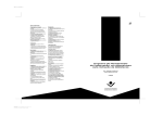
Methodology CO2-tool for electricity, gas and heat from biomass
This document gives background information on the methodology and data sources
used in the CO2 tool. Practical instructions on how to use the CO2 tool can be found in
the user manual that accompanies this tool.
Contact information
This CO2-tool was developed by Ecofys by order of NL Agency. For information on this
tool please contact:
Har van Himbergen, NL Agency, [email protected]
Ella Lammers, NL Agency, [email protected]
Version
1.0
Date
May 2011
Disclaimer
No rights may be derived from this publication, nor may NL Agency be held liable for
the consequences arising from the use thereof.
Table of contents
1
Introduction & background....................................................................... 1
1.1
What can I do with the CO2-tool?............................................................. 1
1.2
Relevant legislation on CO2-calculations.................................................... 1
1.3
CO2-tools .............................................................................................. 2
1.4
How to use this document....................................................................... 3
2
Methodology of greenhouse gas calculations............................................ 4
2.1
Introduction .......................................................................................... 4
2.2
System boundaries ................................................................................ 5
2.3
The greenhouse gas emission of the pathway............................................ 7
2.4
Greenhouse gas emission reduction ......................................................... 8
3
The predefined pathways ....................................................................... 12
3.1
Predefined pathways .............................................................................12
3.2
Electricity and heat from wood pellets by boiler, CHP and Co-firing .............13
3.3
Electricity and heat from wood chips by boiler, CHP and Co-firing ...............17
3.3.1
Electricity from torrefied wood pellets by cofiring in coal plant ....................18
3.3.2
Heat from wood chips by combustion in boiler ..........................................20
3.3.3
Electricity and heat from demolition wood by combustion in CHP ................21
3.4
Green gas production from biogas by mono-digestion of manure, maize,
potato remains, sugar beet remains, glycerine and organic waste ...............22
3.5
Jatropha oil, ready to be used for the production of electricity and/or heat by
means of an diesel engine .....................................................................31
3.6
Rape seed oil, ready to be used for the production of electricity and/or heat
by means of an diesel engine .................................................................34
3.7
Animal fats, ready to be used for the production of electricity and/or heat by
means of an diesel engine .....................................................................38
3.8
Used frying oils, ready to be used for the production of electricity and/or heat
by means of an diesel engine .................................................................40
Reference sources ........................................................................................ 41
Appendix A
Abbreviations and definitions ............................................... 43
i
1
Introduction & background
1.1
What can I do with the CO2-tool?
Biomass can be converted into final energy in the form of electricity, heat or biofuels.
This final energy is considered ‘green’ since it does not result in the release of CO2
with ‘fossil carbon’. However, several steps in producing this final energy from
biomass do generate fossil carbon emission. Examples are: Cultivation and harvesting
(tractors using diesel), transport (trucks, ships using diesel), drying (often natural gas
is used for drying), size reductions (often electricity use), etc. The reduction in
greenhouse gas (GHG) emission compared to final energy from a fossil fuel is
therefore less than 100%. How much less than 100% depends on the type of biomass,
the transport distance and the processing steps. The diversity in biomass, conversion
technologies, ways of transport and the geographical spread of both biomass sources
and the energy demand, result in numerous possible biomass-to-energy pathways.
Each of these pathways has a different GHG emission performance. The calculation of
the total GHG-emission from a specific pathway is time-consuming. The CO2-tool is
software to make these calculations easier.
1.2
Relevant legislation on CO2-calculations
Renewable Energy Directive
In 2009 the Renewable Energy Directive (RED) [1] and the Fuel Quality Directive set
sustainability criteria for liquid biofuels. One of the criteria is a minimum greenhouse
gas saving compared to fossil fuels. Annex V of the RED gives the methodology and
rules to calculate this. This Annex includes a list of typical and default greenhouse gas
emission savings for about 35 biofuel production pathways. The Annex gives for some
of these pathways also the disaggregated emissions (g CO2eq/MJ) per step (cultivation,
processing, transport, etc.).
Report on solid biomass for electricity, heating and cooling
For electricity, heating and cooling from solid and gaseous biomass, there is no
directive that compares to the RED. However, there is a 2010 report from the
European Commission on sustainability requirements for electricity, heating and
cooling from solid and gaseous biomass [2]. In contrast with the RED, this report is
not binding. Annex I of this report gives the methodology and rules to calculate the
greenhouse gas saving compared to fossil fuels. This methodology is analogous to
Annex V of the RED. This Annex includes a list of typical and default greenhouse gas
emission (g CO2eq/MJ) for about 30 pathways. However, the Annex gives no
disaggregated result like Annex V of the RED.
|1
NTA 8080
The NTA 8080 is a Netherlands Technical Agreement on sustainability criteria for
energy purposes [3]. The NTA 8080 refers to the CO2-tool as instrument to determine
the greenhouse performance. Since there is the wish to apply the NTA 8080 in the
near future for the Dutch renewable energy subsidy scheme SDE, it is important that
the CO2-tool is transparent, unambiguous and user friendly.
1.3
CO2-tools
Dutch CO2-tools
A greenhouse gas calculation tool is a software instrument to calculate the greenhouse
gas saving from biomass-to-energy pathways compared to fossil comparators. These
tools are often simple called ‘CO2-tool’. In 2006 – 2007, two CO2-tools were developed
in order by Agentschap NL: one for liquid biofuels for transport from biomass and one
for electricity and heat from biomass.
The Biograce project
The Biograce project (www.biograce.net) develops Excel-based spreadsheets to
calculate the greenhouse gas saving of most of the biofuel production pathways that
are given in Annex V of the RED. The calculations are based on the disaggregated
emissions per step (as given in the Annex V) and standard conversion factors that are
used to calculate the default values in the Annex V of the RED. The spreadsheet
calculations give therefore by definition the same saving compared to fossil
comparators as reported in the RED.
The present CO2-tool
The present CO2-tool is an update of the tool for electricity and heat from biomass as
was developed in 2006 – 2007. However, the format and part of the calculation
methodology is changed drastically. The software environment of the original tool is
abandoned. The Biograce spreadsheet calculation format is the basis of the present
CO2-tool. Despite the fact that the present tool looks and functions like the Biograce
calculation sheets, there are differences compared to Biograce. The most important
are:
1
Since Biograce deals with liquid biofuels, there is in each pathway only one final
biofuel (ethanol, biodiesel). In the present tool, many pathways result in both
electricity and heat. This has consequences in the calculation methodology;
2
The final emission saving that is calculate in the Biogace sheets (a percentage) is
exactly the default greenhouse gas emission saving as listed in Annex V of the
RED. This is possible since most of the parameters that are required for the
calculation of the reduction are known (see also section 1.2). Since the
parameters required for the pathways in the present tool are mostly unknown
(see again section 1.2), it is currently not possible to prepare calculation sheets
that exactly result in the default greenhouse gas emissions that are listed in
|2
Annex I of the report on sustainability requirements for electricity, heating and
cooling from solid and gaseous biomass.
1.4
How to use this document
This document is the methodology document that accompanies the tool (Excel-file)
and the user manual. The first chapter explains what you can do with the tool, what
legislation formed the basis of the development of the tool and gives some
backgrounds on the history of the CO2-tool. Chapter 2 describes the calculation
methodology. The main part of this document is chapter 3 where all pre-defined
pathways are explained in detail. These pathway descriptions are well documented
and referenced.
Besides the tool and this methodology document, there is a user manual that gives
practical information on how to use the tool.
|3
2
Methodology of greenhouse gas calculations
2.1
Introduction
There are many choices to make in GHG-calculations. The most important are:
•
How the complete pathway is build up. Which steps can be identified? For
example: cultivation, harvesting, transport, processing, digestion, biogas
combustion generating electricity and heat.
•
The pathway specific parameters to use. For example: What is the yield of a
certain energy crop (ton/ha)? What is the electric efficiency of a gas engine?
•
The general parameters. For example: the GHG-emission from the use of fossil
fuels in processing or transportation steps, the GHG-emissions resulting from the
use of fertilizer.
•
How to distribute the GHG-burden. For example: when wheat is harvested, there
are two products: wheat grains and straw. How to distribute the CO2-burden from
the cultivation among those two products? This is often referred to as allocation.
In previous CO2-tools, these choices were made by the developers. Some used strict
rules from Life Cycle Analysis while others used more pragmatic approaches. This
resulted in different choices and subsequently different outcomes of calculations. Since
then, some choices were made, resulting in ‘calculation rules’ and more consistency in
GHG-calculations and outcomes. These rules are given in the Renewable Energy
Directive (RED) and the communication ‘on sustainability requirements for the use of
solid and gaseous biomass sources in electricity, heating and cooling’, both discussed
in section 1.2. Next to these documents from the European Commission, there are
other sources that we use in the development of the current tool. Table 2 - 1 gives all
sources, in order of preference in use.
Table 2 - 1
Sources used for methodological choices and parameter selection
Source
1
Comment
European Commission: ‘on sustainability
requirements for the use of solid and
gaseous biomass sources in electricity,
heating and cooling’ (2010) [2]
2
Renewable Energy Directive (2009) [1]
This is on biofuels for transport and
electricity and heat from bioliquids only
3
Biograce calculation tool (2010) [3]
This is on biofuels for transport only
4
CO2-tool for electricity and heat (2006 –
The tool and accompanying document
2008) [5]
as prepared by CML
5
Peer-reviewed literature
Mostly scientific literature
6
Other sources
For example: data from existing
installations.
|4
2.2
System boundaries
The pathway
We consider the complete biomass-to-energy pathways. This means from cultivation
from biomass until the final energy. This final energy can be:
1
Electricity
2
Heat
3
Green gas (upgraded biogas)
The pathway is cut off at the produced final energy. Losses in transport to the
consumer are not included. This is also not included in the fossil comparator. The
process of bringing the final energy on specifications is included in the pathway. This
is for example transformation of electricity to the electricity grid voltage or
pressurizing upgraded biogas to the pressure of the (local) grid pressure.
By-products
By-products are products that are formed in the process from biomass to energy,
other than the final energy or a precursor of the final energy. For example: after
harvesting, wheat is processed into wheat grain and wheat straw. When the wheat
straw is converted to electricity, wheat grain is a by-product. On the other hand, when
wheat grains are fermented and the ethanol is fed to an engine that produces
electricity, wheat straw is a by-product.
Allocation to by-products
Where a pathway produces (besides the energy carrier for which emissions are being
calculated) one or more co-products, greenhouse gas emissions up to the step where
the co-product is formed are distributed among the energy carrier (main product) and
the co-product in proportion to their energy content. Part of the CO2-burden is
allocated to the co-product in this way. This allocation takes only place for by-products
and not for wastes.
(By-)product or waste?
Since part of the CO2-burden allocates to by-products and not to wastes, it is
important to distinguish by-products and wastes. The communication [2] of the EC is
guiding, but not comprehensive in this. Also the RED [1] and the NTA 8080 [3] are
guiding.
Wastes
When the starting material for a pathway is a waste, the greenhouse gas emissions up
to the point of collection of the starting material is considered zero ([2], Annex I, point
16, third paragraph). In other words: the pathway is considered only from the point of
|5
collection; the steps before that are irrelevant and therefore not included in the CO2tool.
Allocation in case of CHP
Biofuels for transport pathways (RED, Biograce) always result in a single product: the
biofuel (ethanol, biodiesel). The greenhouse gas emission saving is in that case the
ratio between the total greenhouse gas emission from the pathway divided by the
pathway of the fossil comparator. Pathways of solid biomass used for electricity,
heating and cooling are different in this aspects. In CHP-pathways more than one final
product is formed, often electricity and heat. The greenhouse gas emission are in
these cases distributed among the energy carriers. The allocation factors for electricity
and heat are (see Annex I, point 1b and 15 of [2]):
•
Allocation factor for electricity
•
Allocation factor for heat
Cel × η el
Cel × η el + C h × η h
C h ×η h
=
C el × η el + C h × η h
=
Where:
Cel
Fraction of exergy in the electricity (=1)
Ch
Fraction of exergy in the heat (Carnot efficiency):
For Th N 150°C: 1 - (273/Th)
For Th < 150°C: 0.3546 (=Carnot efficiency at 150°C)
Th
Temperature of useful heat at point of delivery as final energy (K)
Rel
Electric efficiency
Rh
Heat efficiency
In the calculation of the thermal efficiency, only ‘useful heat’ is accounted for. This
excludes heat that is used within the energy generation installation self (parasitic
load) and heat that is destroyed or lost. The efficiency is based on annual useful heat
output divided by annual energy input.
Parasitic load
Every energy generation installation uses part of the energy produced to maintain the
processes: the parasitic load. Examples of this are: electricity for flue gas cleaning
equipment, pumps, fans and heat for maintaining the optimum digestion temperature.
The parasitic load varies and depends on the type of installation. The parasitic load
makes the difference between gross and net energy production. In accordance with
the Communication ([2], Annex I), the efficiencies are based on net energy
production, so excluding parasitic load. The energy production input numbers in the
CO2-tool are therefore net energy productions in any case.
Final products
|6
The tool contains two types of pathways:
1 solid or gaseous biomass
electricity and/or heat and green gas
2
biomass
biofuels / bioliquids
We calculate the first type of pathways according Annex I of Communication [2]; the
second type according Annex V of the Renewable Energy Directive (RED) [1]. This is
because the RED covers (a) biofuels for transport and (b) bioliquids used in other
sectors (electricity, heating and cooling) (see [1], Introduction, first sentence). A
consequence is that the final product with type 1 is electricity and heat, while the final
product in type 2 is a fuel. After all, the RED deals only with biofuels and bioliquids as
final product of the pathways (see Annex V of [1], section C, point 2). This is in
contrast with the analogous Annex I of [2], point 2). Another consequence is that
other fossil comparators are used (see section 2.4 under ‘Fossil comparators’).
2.3
The greenhouse gas emission of the pathway
According to RED, greenhouse gas emissions from the production of solid and gaseous
biomass fuels, before conversion into electricity and heat are calculated as (as given in
[2], Annex I, point 1a):
•
E = eec + el + e p + etd
+ eu − esca − eccs − eccr
Where:
E
total emissions from the production of the fuel before energy conversion
eec
emissions from the extraction or cultivation of raw materials
el
annualised emissions from carbon stock changes caused by land use
ep
emissions from processing
etd
emissions from transport and distribution
eu
emissions from the fuel in use, that is green house gases emitted during
the combustion of solid and gaseous biomass
esca
emission savings from soil carbon accumulation via improved agricultural
management
eccs
emission savings from carbon capture and geological storage
eccr
emission savings from carbon capture and replacement
Emissions from the manufacture or machinery and equipment is not taken into
account in the methodology.
The final step is the calculation of the total greenhouse gas emissions from the final
energy commodity (as given in [2], Annex I, point 1b):
•
a single commodity:
ECi =
E
ηi
Where:
ECi
total greenhouse gas emissions from the final energy commodity I
|7
(electricity or heat)
The efficiency of the conversion (=Rel or Rh or Rc)
i
•
more than one commodity (CHP):
ECi =
E
ηi
Ci × η i
Cel × η el + C h × η h
The greenhouse gasses taken into account are carbon dioxide (CO2), methane (CH4)
and nitrogen dioxide (N2O). The total greenhouse gas emission is expressed in g CO2eq
per MJ of final commodity. The CO2 equivalents are:
•
1 g CO2 = 1 g CO2eq
•
1 g CH4 = 25 g CO2eq
•
1 g N2O = 298 g CO2eq
Note that these global warming potentials are slightly different from the ones
prescribed in [2] (23 and 296 instead of 25 and 296). We use these values because
these were used by the European Commission in calculating the default values in the
RED [1]. It is expected that these values will be used in future European legislation.
Emissions from combustion
Emissions of greenhouse gases from the combustion of the final fuel are assumed zero
according [2], Annex 1, point 12 and the definition of eu in abovementioned definition
of E.
2.4
Greenhouse gas emission reduction
Fossil comparators
The fossil comparators are:
•
198 g CO2eq / MJ electricity (from [2], solid and gaseous biomass)
•
87 g CO2eq / MJ heat (from [2], solid and gaseous biomass)
•
91 g CO2eq / MJ fuel in electricity production (from [1], bioliquids)
•
77 g CO2eq / MJ fuel in heat production (from [1], bioliquids)
•
85 g CO2eq / MJ fuel incogeneration (from [1], bioliquids)
The communication [2] reports no fossil comparators for biogas and green gas. In the
present tool we use:
|8
•
67.59 g CO2eq / MJ green gas1
Calculation of emission reduction
The greenhouse gas emission reduction is the total greenhouse gas emission of the
pathway, divided by the total greenhouse gas emission of the pathway of the fossil
comparator (as given in [2], Annex I, point 1b):
•
SAVING of i =
1−
EC i
fossil comparator of i
where i is the final commodity (electricity, heat).
In case of the production of both electricity and useful heat in a CHP, the saving will
be expressed in both commodities;
•
•
EC heat
87
EC electricity
SAVING for electricity = 1 −
198
SAVING for heat =
1−
In order to get a single value that can be compared with other CHP’s, the tool
computes an overall GHG emission reduction (this is not part of the calculation
methodology in [1] and [2]). This overall GHG emission reduction is the weighted
average of the saving for heat and the saving for electricity, with the allocation factors
for electricity and heat as weighting factors. For example: when a pathway gives an
emission reductions of 90% for heat and 87% for electricity and allocation factors of
20% for heat and 80% for electricity, the overall GHG emission reduction is:
20% x 90% + 80% x 87% = 88%.
General calculation methodology
The CO2-tool calculates the total greenhouse gas emissions from a number of
pathways. The calculations are based on two types of numbers:
Input numbers
default values in tool; can be changed by user
•
•
Standard values
fixed values in tool; cannot be changed by user
Table 2 - 2 gives the most important of these numbers.
9/47
1
This is the emission factor used in Biograce for ‘Natural gas (4000 km, EU Mix
qualilty)’. This is 16% higher than the 56.7 emission factor from natural gas as
commonly used in the Netherlands and is reported in among others [6]. However, the
latter value includes only the combustion emissions and not the emissions from
transport and extraction.
|9
Table 2 - 2
Input numbers and standard values
Type
Sub-type
Input numbers
Energy use
Examples
The production of one ton wood pellets from
sawdust requires 414 MJ electricity.
Material use
Per hectare maize, 185 kg N-fertilizer is used
for cultivation.
Yield / moisture content
One kg of wet sewage sludge gives 44 g of
GHG emission factors
One MJ of natural gas gives 63 g CO2, 0.20 g
dried sewage sludge.
Standard values
of CH4 and 0.00022 N2O.
Lower heating values
The heating value at o% moisture of wood
pellets is 17.1 MJ/kg.
Global warming
The GWP of N2O is 296 on mass basis.
potentials (GWP)
Transport efficiencies
The fuel efficiency of a dry bulk diesel truck
is 0.94 MJ/ ton / km
Transport exhaust gas
A dry bulk diesel truck produces 0.005 g CH4
emissions
per ton per km.
The user manual of the CO2-tool explains in detail how this calculation methodology is
implemented in the CO2-tool.
Co-digestion pathways
Co-digestion is the digestion of manure and co-substrates in the same installation with
a single reactor. Since the ratio between manure and co-substrate varies and more
than one co-substrate can be used in a digester, there are more variables in codigestion pathways compared to other pathways such as the combustion of solid
biomass. In order to maintain the general structure and format used in the CO2-tool,
the co-digestion pathways are split in separate pathways on separate calculation
sheets. An example of a feed (mass-%) to a co-digester is: 30% pig manure, 15%
cattle manure, 5% chicken litter, 40% maize and 10% crude glycerine. In this case,
the calculation consists of three pathways: for manure (one sheet for all types), for
maize and for crude glycerine. Each of these pathways is according the general
structure and format. However, the pathways are rather different. Manure is a waste
and the pathway starts therefore with the collection of manure while the maize
pathway starts with the cultivation and harvesting of maize. Finally, there is a single
sheet for the co-digestion pathways. In this calculation sheet, the user fills in the
composition of the feed only. This sheet calculates the greenhouse gas emission from
the co-digestion by taking the data from the sheets of each of the fees streams (in the
example: manure, maize and crude glycerine). The weighting factor is the amount of
biogas arising from the substrate. For the example, this means that the only 10% of
crude glycerine in the feed, contributes more to the final result than the 50% manure
| 10
since the specific biogas yield of crude glycerine is about 40 times higher than manure
(see Table 3 - 11 on page 29).
It is important to notice that the separate sheets for the co-substrates are based on
co-digestion. These sheets should not be used for calculating a mono-digestion of that
co-substrate.
Land use change (LUC)
A land use change (LUC) occus when the carbon stock per hectare is different for the
biomass crop and the reference situation. Therefore, LUC does not occur in pathways
based on wastes. Annual emissions from carbon stock changes due to land use change
are calculated by spreading the total emissions over twenty years. The carbon stock
change is calculated in a separate sheet in the tool that is accessible from the sheets
with the pathways. This calculation sheet is based on the sheet within the Biograce
project [4] and fully in accordance with the “Commission decision of 10 June 2010 on
guidelines for the calculation of land use carbon stocks for the purpose of Annex V of
the Directive 2009/28/EC”. Indirect LUC is not included in [1], [2], [4] and the current
tool.
| 11
3
The predefined pathways
3.1
Predefined pathways
The CO2-tool includes a number of predefined pathways. These pathways are defined
by:
•
Input blocks (see user manual) for each of the steps in the pathway;
•
Default values for the input values in the blocks (see user manual; these values
can be changed by the user, but when unknown, the pre-filled-in values can be
used).
•
Pre-defined Standard values
Currently the following pathways are predefined in the CO2-tool:
1
Heat from wood pellets by combustion in boiler
2
Electricity from torrefied wood pellets by cofiring in coal plant
3
Electricity from wood pellets by cofiring in coal plant
4
Electricity and heat from wood pellets by combustion in CHP
5
Electricity and heat from demolition wood by combustion in CHP
6
Heat from wood chips by combustion in boiler
7
Electricity and heat by combustion of biogas from mono-digestion of manure
8
Electricity and heat by combustion of biogas from mono-digestion of maize
9
Electricity and heat by combustion of biogas from mono-digestion of organic
waste
10 Electricity and heat by combustion of biogas from mono-digestion of glycerine
11 Electricity and heat by combustion of biogas from mono-digestion of potato
remains
12 Electricity and heat by combustion of biogas from mono-digestion of sugar beet
remains
13 Electricity and heat by combustion of biogas from co-digestion of manure + cosubstrate (co-substrates to select from 8 , 10 , 11 and 12 by user)
14 Green gas from manure by mono-digestion
15 Green gas from silage maize by mono-digestion
16 Green gas from organic waste by mono-digestion
17 Green gas from glycerine by mono-digestion
18 Green gas from potato remains by mono-digestion
19 Green gas from sugar beet remains by mono-digestion
20 Green gas from manure + co-substrate by co-digestion (co-substrates to select
from 15 , 17 , 18 and 19 by user)
21 Rape seed oil, ready to be used for the production of electricity and/or heat by
means of an diesel engine
22 Jatropha oil, ready to be used for the production of electricity and/or heat by
means of an diesel engine
| 12
23 Animal fats, ready to be used for the production of electricity and/or heat by
means of an diesel engine
24 Used frying oils, ready to be used for the production of electricity and/or heat by
means of an diesel engine
The coming paragraphs detail these predefined pathways. The pathways that are
strongly related with each other are described together in one paragraph. These are
the pathways of wood pellets and wood chips for the production of electricity and/or
heat and the pathways of digestion with different substrates. Every paragraph starts
with a block diagram of the pathway, including all inflows (feedstock, material use,
energy use, GHG emissions and commodities). A detailed description of each of the
blocks follows the block diagram. This description includes the default input numbers,
a motivation why a number was selected and for each number a reference to the
(literature) source.
The abovementioned pathways 21 - 24 are pathways of liquid biomass. The
methodology is therefore completely analogous to Biograce (see also ‘Final products’
in section 2.2).
3.2
Electricity and heat from wood pellets by boiler, CHP and Co-firing
Process description
The system described here documents routes through which sawdust is converted into
wood pellets that are used as feedstock for electricity and heat production through
three different conversion technologies, i.e. combustion in boiler, combustion in CHP
and co-firing in a coal-fired power plant. The flowchart of the process is illustrated in
Figure 3 - 1.
| 13
Sawdust
Electricity
Pelletization
Wood pellets
Fuel
Transportation
Transported wood pellets
Combustion in
boiler
Combustion in
CHP
Heat
Heat
Figure 3 - 1
Transported wood pellets
Co-firing in coalfired power plant
Electricity
Electricity
Flowchart of pathway of electricity and heat production from combustion of wood
pellets in CHP, boiler and coal plant (co-firing)
The electricity production pathway is separated into the three stages listed below:
•
Pelletization
•
Transportation of wood pellets
•
Combustion in boiler, CHP or coal plant (co-firing)
The sawdust from wood processing is pressed to wood pellets in Canada. We assume
that the production of sawdust and the pellet production occurs at the same site. The
produced pellets are then shipped by truck to a harbour and loaded onto a
transoceanic ship, which transports the pellets to a harbour in the Netherlands
(Rotterdam harbour). The pellets are then transported through road transport to a
power plant where they are used as a feedstock for electricity and heat production
through different means.
Typically, wood pellets are used in 3 different appliances; combustion in boiler for the
production of heat, combustion in CHP for the combined production of electricity and
heat and co-combustion in a large coal-fired power plant. Direct emission of CO2 from
the combustion of wood pellets can be neglected as CO2 is assumed to be biogenic.
Other emissions from wood pellet combustion are also neglected following the
calculation methodology in Annex I of [2].
| 14
The wood used for pellets is a waste product from lumber manufacturing. Therefore,
the system extends upstream to the point where wood residue is generated at a saw
mill. The residue is considered a waste, and emissions resulting from the operation of
the saw mill are not attributed to the wood residue. We assume there are no losses in
collection of sawdust.
Pelletization
During the processing, wood waste such as sawdust and shavings are produced with a
moisture content of around 40% [8]. This waste wood is then dried and pressed into
wood pellets on-site. Drying can be accomplished using electricity or by burning a
portion of the waste wood in a furnace used for heating. We assume that the
pelletization process uses only electricity. Wood pellets typically have 6% moisture
content. Assuming a material loss of 1%, the yield of wood pellets will be around
0.632 ton pellets per ton of sawdust (this is: (1-0.4)/(1-0.06)*0.99 = 0.632).
For the processes defined above, the difference between the wood pellet
manufacturing in Europe and that in Canada relates to the electricity used. Each of
these locations has different amounts of renewable electricity present in their
electricity mix. We assume that the pellets are produced in Canada, which has a much
lower emission factors due to a larger share of renewable energy in electricity
production (>50% renewable due to hydroelectricity). The electricity emission factors
for Canadian mix are taken from [5]. The electricity requirement for pellet production
is typically 115 kWh per ton pellets [5].
Transportation of wood pellets
The produced pellets are then transported by truck to a harbour and loaded onto a
transoceanic ship, which transports the pellets to a harbour in the Netherlands.
Transport from the processing plant to the harbour is done by lorry. We assume a
representative distance of 60 km, as reported in [5]. Further, we assume that the
shipment of the pellets from Canada to the Netherlands is accomplished through a
9,000 ton transoceanic freighter using HFO as fuel. The distance between Eastern
Canada to Rotterdam is typically reported to be 5,000 km [5].
Once in the Netherlands, transport of the wood pellets will be done by lorry. A local
combustion plant would be 100 km away from the harbour, and could be feasibly
serviced by a 28t lorry. Consequently, the total distance for transportation of wood
pellets equals 160 km. The transport losses are assumed to be 1%.
Combustion in boiler
The typical application of wood pellets in the CO2-tool is the combustion in a small
scale decentralized heat production system with a thermal capacity of <1 MWth. Wood
pellets are brought to the plant as main feedstock. Possible small amounts of fuel oil
used to ignite the burner are neglected. The process is assumed to have an efficiency
| 15
of 90%, which is typical for small combustion systems for heat production. The
functional unit is defined as the supply of low temperature heat (90°C). We assume
there is no loss of pellets. The user should fill in the actual performance parameters of
the boiler. The example values in the tool are given in Table 3 - 1.
Table 3 - 1
Example values conversion step in pathway wood pellet boiler (basis is Y750 kW boiler
@ 8500 h/year)
Parameter
Starting value
Unit
Useful heat
23225
GJheat / year
Temperature
90
°C
Input
1500
tonTransported pellets / year
Combustion in CHP
The described system refers to a medium scale centralized electricity production
system with a net power output of 5 MWe. Wood pellets are brought to the power
plant as main feedstock. Amounts of fuel oil are used to ignite the burner are
neglected. The production of electricity is delivered to the high voltage grid, and finally
converted to low voltage electricity grid. The produced heat is also considered a
product. The user should fill in the actual performance parameters of the CHP. The
example starting values in the tool are given in Table 3 - 2.
Table 3 - 2
Example values conversion step in pathway wood pellet CHP (basis is Y5 MWe CHP @
8000 h/year)
Parameter
Starting value
Unit
Electricity
40000
MWhelectricity / year
Useful heat
250000
GJheat / year
Temperature
90
°C
Input
33000
tonTransported pellets / year
Combustion in coal plant (co-firing)
Electricity is produced in a large scale centralized coal-fired power plant. Wood pellets
are directly co-fired with coal. Coal is mined and transported to the power plant as
main feedstock. The electricity production of the co-firing process is separated into 2
parts: for wood pellets and for coal, based on the energy content of the fuels. Only the
electricity from wood pellets and the accompanying necessary inputs are taken into
account. The heat is considered a waste and the system is optimized for electric
efficiency [5].
The user should fill in the actual performance parameters of the CHP. The example
starting values in the tool are given inTable 3 - 3.
| 16
Table 3 - 3
Example values conversion step in pathway wood pellet co-firing (basis is Y 850 MWe
power plant @ 8760 h/year and 10% co-firing)
Parameter
Starting value
Unit
Electricity
750
GWhelectricity / year
Useful heat
0
TJheat / year
Temperature
0
°C
Input
400
ktonTransported pellets / year
3.3
Electricity and heat from wood chips by boiler, CHP and Co-firing
Process description
The system described here documents routes through which wood waste (from wood
processing) or demolition wood (wood after use) is converted into wood chips and
then used as a fuel for electricity and heat production through three different
conversion technologies, i.e. combustion in boiler, combustion in CHP and co-firing in
a coal plant as torrefied wood pellets. The flowchart of the processes is illustrated in
Figure 3 - 2.
| 17
Wood waste / demolition wood
Electricity
Chipping
Wood chips
Fuel
Demolition wood chips
Transportation
Drying
Electricity
Transported chips
Combustion in
boiler
Electricity
Magnetic
separation
Dry chips
Torrefaction
Wood chips
Fuel
Transportation
Torrefied pellets
Heat
Fuel
Transportation
Transported chips
Combustion in
CHP
Transported pellets
Co-firing in coalfired power plant
Heat
Electricity
Electricity
Figure 3 - 2
Flowchart of pathway of electricity and heat production from combustion of wood chips
in CHP, boiler and coal plant (co-firing after torrefaction)
We assume that all pretreatment steps (chipping, torrefaction, etc.) take place at the
same site as where the waste comes available. The produced fuel is then transported
to the power plant where it is used for electricity and/or heat production. The systems
described in this section extend upstream to the point where wood residue is
generated.
As stated before, emission of CO2 from any combustion of wood can be neglected as
CO2 is assumed to be biogenic. Other emissions from wood combustion are also
neglected following the calculation methodology in Annex I.
3.3.1 Electricity from torrefied wood pellets by cofiring in coal plant
This section describes the pathway of using torrefied wood chips for co-firing in a coalfired power plant. Torrefaction of wood is a process through which the woody
feedstock is converted into a product that has increased energy density and
| 18
characteristics that make it easy to handle and transport and therefore become
suitable to co-fire in existing coal-fired power plants at high co-firing percentages.
The wood is assumed to originate from Canada, where it is chipped, dried, torrefied
and pelletized at the same site as where the wood processing residues become
available. The resulting torrefaction pellets are combusted in a Dutch coal-fired power
plant after transportation by ship to the Netherlands. The pathway through which
electricity is produced by co-firing torrefaction pellets consists of five:
•
Chipping of wood waste
•
Drying of wood chips
•
Torrefaction of wood chips and pelletization to torrefaction pellets
•
Transportation of torrefaction pellets
•
Co-firing of torrefaction pellets in coal-fired power plant
Chipping of wood waste
The wood used for chipping is a waste product from lumber manufacturing in the
Canada. The initial moisture content of wood waste approximates 50%. If the wet
wood is allowed to dry for a few months in the air the moisture content is lowered to
about 30%. With the assumption of 1% wood loss during chipping, the yield of wood
chips will be around 0.707 ton chips per ton wood waste (this is: (1-0.5)/(1-0.3) *
0.99 = 0.707). The average electricity consumption during the chipping process is
reported to be 75 kWh per ton wood waste [5].
Drying of wood chips
The biomass should be dried a further 15% to 10% in order it to be suitable for the
torrefaction process [14]. This is one of the most important steps in the total
torrefaction process, as evaporation of water is very energy consuming. The energy
for the drying is generated by a furnace that is fuelled with a part of the wood chips.
We assume this requires 15% of the total wood chips. Therefore, no fossil fuel is
required for the drying process. Because of the weight loss during the drying process,
the dry chips yield will be 0.778 ton per ton fresh chips (this is: (1-0.3)/(1-0.1). Since
15% is used for the drying, this is 0.661 ton per ton fresh chips.
Torrefaction of wood chips
Torrefaction is a thermal pre-treatment technology performed at atmospheric pressure
in the absence of oxygen. The dried wood chips are brought into the torrefaction
reactor that operates at around 250°C. It is assumed that heat for the process is
supplied by the ‘tor gas’ from the torrefaction process itself. The wood chips will
convert into a solid uniform product with very low moisture content and a high calorific
value compared to fresh biomass. Torrefied biomass typically contains 70% of its
initial weight (the mass yield) and 90% of the original energy content [14]. After
torrefaction, it is common to pelletize the material. This is seen as part of the
torrefaction process here. The LHV of torrefied wood pellets is in the range of 18-23
MJ/kg [14] at 97% dry substance. Based on this, it is assumed to use an average LHV
| 19
of 21.13 MJ/kg for dry torrefied pellets. The electrical input to the system is reported
to be 102 kWh per ton wood input (including size reduction and pelletization) [14].
Transportation of torrefied wood
The transportation route of torrefied wood pellets is similar to the transportation route
of wood pellets from Canada described in section 3.2, i.e. 5000 km ocean shipping and
160 km road transport with a material loss of 1% during transportation.
Combustion in coal plant (co-firing)
This process is the same process as the coal-fired power plant described in section
3.2. Thus, the system is optimized for electric efficiency without the utilization of heat.
The user should fill in the actual performance parameters of the coal-fired power
plant. The example values in the tool are given in Table 3 - 4.
Table 3 - 4
Example values conversion step in pathway torrified wood pellets co-firing (basis is Y
850 MWe power plant @ 8760 h/year and 10% co-firing)
Parameter
Starting value
Unit
Electricity
750
GWhelectricity / year
Useful heat
0
TJheat / year
Temperature
0
°C
Input
335
ktonTransported pellets / year
3.3.2 Heat from wood chips by combustion in boiler
The system described in this section represents a small scale combustion plant using
fresh wood chips from the Netherlands as feedstock. Wood chip boilers can be used to
provide central heating or process heating. They can be installed alongside, or to
replace, existing gas, coal, or oil boilers. This system includes the next processes:
•
Chipping of wood waste
•
Transportation of wood chips
•
Combustion in boiler
Chipping of wood waste
The starting material are prunings and trimmings. The initial moisture content of this
woody waste approximates 50%. If the wet wood is allowed to dry for a few months in
the air the moisture content is lowered to about 30%. We assume 1% wood loss
during chipping. The resulting yield of wood chips is then 0.707 ton chips per ton wood
waste (this is (1-0.5)/(1-0.3) * 0.99).
The average electricity consumption during the chipping process is reported to be 75
kWh per ton wood waste [5].
| 20
Transportation of wood chips
Transport of wood chips will be by lorry. A local biomass conversion plant is assumed
to be 100 km away from wood chips production site and could be feasibly serviced by
a 28t lorry. The transport losses are neglected.
Combustion in boiler
The typical application of wood chips in the CO2-tool is the combustion in a small scale
decentralized heat production system with a thermal capacity of <1 MWth. Wood
pellets are brought to the combustion installation as main feedstock. Possible small
amounts of fuel oil used to ignite are neglected. The process is assumed to have an
efficiency of approximately 90%, which is typical for small combustion systems for
heat production. The functional unit is defined as the supply of low temperature heat
(90°C). The user should fill in the actual performance parameters of the boiler. The
example values in the tool are given in Table 3 - 1.
Table 3 - 5
Example values conversion step in pathway wood chips boiler (basis is Y750 kW boiler
@ 8500 h/year)
Parameter
Starting value
Unit
Useful heat
23225
GJheat / year
Temperature
90
°C
Input
2000
tonTransported pellets / year
3.3.3 Electricity and heat from demolition wood by combustion in CHP
Demolition wood produced during demolition of buildings is another feedstock that can
be used for the production of electricity and heat. The pathway does not differ much
from the system of combustion of wood chips in a boiler described in section 3.3.2.
The only difference is the source of the feedstock and an additional separation process
to separate woody biomass from inert fraction such like metals and other
contaminations. The system consists of the following processes:
•
Chipping of demolition wood
•
Magnetic separation
•
Transportation of wood pellets
•
Combustion in CHP
Chipping of demolition wood
The moisture content of demolition wood approximates 12% [13]. When neglecting
wood losses during chipping, the yield of wood chips will be around 1 ton chips per ton
wood waste as the moisture content of wood will be the same after the chipping
process. The average electricity consumption during the chipping process is reported
to be 75 kWh per ton wood waste [5].
Magnetic separation
| 21
The magnetic separation process is intended to remove nails and other fasteners from
the demolition wood. This process takes place at the same location as chipping. The
electricity requirement for this process is reported to be 0.6 kWh average per ton
wood chips [5]. We assume a 1% loss by the removed materials.
Transportation of demolition wood chips
The chipped demolition wood is transported to the plant by truck. A local biomass
conversion plant is assumed to be 50 km away from wood chips production site [5].
The transport losses are neglected.
Combustion in CHP
The described system refers to a medium scale centralized direct combustion power
plant with a net capacity of 5 MWe. The system burns chipped and cleaned demolition
wood directly in boilers that supply steam for the same kind of steam-electric
generators used to burn fossil fuels. A small amounts of fuel oil are possibly used to
ignite the burner are neglected. The production of electricity is delivered to the high
voltage grid, and finally converted to low voltage electricity grid. The produced heat is
considered as a product. The user should fill in the actual performance parameters of
the CHP. The example values in the tool are given in Table 3 - 2.
Table 3 - 6
Example values conversion step in pathway demolition wood chips CHP (basis is Y5
MWe CHP @ 8000 h/year)
Parameter
Starting value
Unit
Electricity
40000
MWhelectricity / year
Useful heat
250000
GJheat / year
Temperature
90
°C
Input
33000
tonTransported pellets / year
3.4
Green gas production from biogas by mono-digestion of manure, maize,
potato remains, sugar beet remains, glycerine and organic waste
Process description
The system described here documents routes through which 6 different substrates,
i.e. manure, maize, organic waste (in Dutch: GFT), potato remains, sugar beet
remains and glycerine can be used as a feedstock for the production of biogas through
anaerobic mono-digestion which subsequently will be upgraded to green gas. Green
gas is upgraded biogas with 88 volume-% methane. Apart from the pathway for
maize, all pathways of the substrates do not include a cultivation phase as they are
waste streams. Therefore, the pathways for all the substrates are identical except the
pathway for maize which includes an additional cultivation phase. The flowchart of the
process is illustrated in Figure 3 - 3.
| 22
Figure 3 - 3
Flowchart of pathway of green gas production from mono-digestion of different
substrates and electricity and heat production from combustion of biogas
The green gas production pathway includes the five stages listed below:
•
Transport of substrate
•
Storage of substrate
| 23
•
Anaerobic mono-digestion of substrate
•
Biogas upgrade
•
Compression of green gas and injection to the net
For the production of electricity and heat, the system includes a CHP process instead
of upgrading and compression processes. The system processes will then be:
•
Transport of substrate
•
Storage of substrate
•
Anaerobic mono-digestion of substrate
•
Combustion in CHP
The described system refers to a large scale centralized system (typically 1.5 – 5 MWe
in case of a CHP configuration). This means that the processes for feedstock
production, conversion and end use are situated on different sites and therefore
transport of substrate, digestate (digested substrate) and energy is taken into
account. In CHP-configurations, part of the produced electricity and heat is used for
the operation of the digester (heat for the digestion tanks and electricity for pumps
etc.) In the case of green gas as final commodity, part of the produced biogas is used
for heating the digestion tanks. Electricity is purchased from the grid. It is important
that net electricity and heat production is filled in the tool instead of gross values.
Manure, organic waste (GFT), potato remains, sugar beet remains and glycerine are
considered waste streams which means that emissions of GHG from livestock
husbandry, agricultural production and food industry are not considered part of the
production of green gas. Therefore, the system is cut off at the production of these
substrates and that upstream processes are not taken into account. Silage maize is
considered an energy crop. Therefore, the system starts at the production of maize
which includes cultivation, harvesting, mechanical treatment and transportation. The
downstream processes for maize are identical to other pathways.
The emissions from the storage of digested substrate up to the application of it on
land will be excluded from the system as the produced digestate is considered a
produced waste. Therefore, nothing is allocated to the digestate. Emissions from the
digestate storage are not included, according the biogas pathways in Biograce [4].
Greenhouse gases will be emitted during the combustion of biogas. However, as
stated before, the emissions from the fuel in use emitted during the combustion of
solid and gaseous biomass should be neglected according to the calculation
methodology in Annex I of [2].
The heating values and the moisture contents of substrates are the important
parameters that influence the GHG emissions. An overview these parameters per
substrate and the source of the numbers is given Table 3 - 7.
| 24
Table 3 - 7
Moisture contents of the substrates
Lower heating
Source
Moisture
Source
value LHV (dry)
LHV
content
moisture
[%]
content
[MJ/kg]
Manure
10.0
[4]
92
[4]
Maize
18.5
[4]
70
[20]
Potato remains
5.0
[15]
22
[5]
Sugar beet remains
6.5
[15]
17
[5]
Organic waste (GFT)
10.9
[5]
54
[5]
Glycerine
16.0
[4]
0
[5]
Mono-digestion and co-digestion
The six substrates that are mentioned in this section are not all suitable or likely to be
used for mono-digestion or co-digestion. This is indicted in Table 3 - 8.
Table 3 - 8
Possible use of substrates in mono- and co-digestion
Mono-digestion
Co-digestion with manure
Manure
yes
Not applicable
Maize
Yes
Yes
Potato remains
No
Yes
Sugar beet remains
No
Yes
Organic waste (GFT)
Yes
No
Glycerine
No
Yes
The main reason that municipal organic waste (Dutch: GFT) is not co-digested with
manure is that the digested material from organic waste can be composted. Compost
is a more valuable material than digestate (digested manure). The parameters that
describe the pathway of organic waste digestion are similar to the other pathways. For
this reason, organic waste is treated alike the co-substrates in this section.
How the GHG emission savings in co-digestion pathways are calculated in the tool, can
be found in the accompanying user manual.
Cultivation of maize
The production, including cultivation, harvesting and transportation, of silage maize
occurs off site. Because maize is an (energy) crop, the emissions related to the
production of maize should be taken into account. In this case, the emissions during
the production of maize are based on KWIN data for silage maize cultivated on sandy
soil in southern and eastern part of the Netherlands [20]. These regions are known as
the most important cultivation zones for silage maize in the Netherlands. Silage maize
will be produced with a yield of 13,060 kg dry substance per hectare with a moisture
| 25
content of 70%. This corresponds to a wet yield of 44 ton per hectare. For the
cultivation of silage maize, 185 kg of N-fertiliser and 150 kg of K2O-fertiliser per
hectare is required. Besides that, 50 litre of diesel (equal to 1,793 MJ) per hectare is
required for harvesting and transport of the product. This equals to 1,793 MJ diesel
per hectare. The field N2O emission during the production of silage maize in sandy soil
in the Netherlands is reported to be 1.92 kg N2O per hectare [21].
Transport of substrate
It is assumed that manure will be collected from local farms. Therefore a transport
distance of 10 km is assumed, using 28t trucks [4]. Maize, potato remains and sugar
beet remains will be transported to the site over a distance of 50 km, using 28t lorries
[4]. For organic waste (GFT), an average transportation of 100 km is assumed to the
site [5].
There are a few biodiesel plants in Netherlands that produce glycerine. Therefore, it is
likely that crude glycerine is imported from European (mainly Germany) biodiesel
plants through road transport. It is assumed that glycerine will be transported to the
site over a distance of 150 km, using a 28t lorry. It is assumed that there will be no
loss of substrates during the transportation from production location to the site.
An overview of the assumed transportation distances is given in Table 3 - 9.
Table 3 - 9
Assumed transportation distances
Assumed transportation
distance to the site [km]
Manure
10
Maize
50
Potato remains
50
Sugar beet remains
50
Organic waste (GFT)
100
Glycerine
150
Storage of substrate
Maize, potato remains, sugar beet remains, organic waste (GFT) and glycerine is
assumed to be stored on site over a longer period compared to manure. Therefore,
emissions may occur from the storage of this biomass. In the tool as developed by
CML [5], the GHG emissions are reported to be 3.1 kg CH4 and 0.014 kg N2O per
tonne of manure, maize, organic waste or potato remains [5] as conservative and
typical values (for all these substrates the same). The ‘best available’ values are zero.
In Biograce, only biogas from manure and organic waste pathways are included. Here,
the emissions from storage are neglected. CML [5] extracted the values from Alterra
report [19]. In this report, storage is assumed in the form of silage (Dutch: inkuilen).
The reported emission factors (that are adopted by CML) are based on this type of
| 26
storage. However, based on the characteristics of potato remains, sugar beet remains
and organic waste (GFT) we know that storage of these products is not done by silage.
Moreover, the mentioned materials are waste products and subsequently not stored
for the purpose of digestion only. When these materials are not digested, they are
stored to be used as animal feed. The numbers reported by CML are therefore not
applicable for these materials. Therefore we adopt the zero-emission assumption of
Biograce and the also zero ‘best available’ value of CML. Since glycerine is stored in
tanks, zero emissions are assumed there.
Ensilage is applicable to maize. This suggests to use the 3.1 kg CH4 and 0.014 kg N2O
per tonne for the storage of maize. Reviewing the assumptions in the Alterra report
[19], we notice that the authors assume that these emissions from cosubstrates is the
average of pig and cattle manure (average of 1.8 and 4.65 Y 3.1) because of the lack
of actual numbers. This makes the value of 3.1 for maize questionable as well. Since
in silages the material is covered by plastic to avoid aerobic degradation of the
material (loss of material and quality), the formation of 3.1 kg methane (=4.7 m3) per
tonne of maize would be noticeable. In practice, this is not observed. Therefore we
reject this value.
Finally, the Alterra report [19] states that 95% of the reported maximum emissions
from the storage of manure can be avoided by minimizing the storage period. Based
on the typical storage capacity of digesters that are in operation in the Netherlands,
we can conclude that the storage period (on site) is short. For this reason we assume
an emission from manure storage of 5% of 3.1 and 0.014, which is 0.155 kg methane
per tonne of manure and 0.0007 kg N2O per tonne of manure. This is based on 50%
pig and 50% cattle manure.
An overview of the assumed GHG emissions during the storage of the substrates is
given in Table 3 - 10.
Table 3 - 10
Emissions during storage per substrate
CH4
N2O
[kg/ton substrate]
[kg/ton substrate]
Manure
0.155
0.0007
Maize
0
0
Potato remains
0
0
Sugar beet remains
0
0
Organic waste (GFT)
0
0
Glycerine
0
0
Anaerobic mono-digestion of substrate
This step in the pathway includes the anaerobic digestion of the substrate. Typical
values for the biogas yield and the methane content of the produced biogas from
| 27
different substrates are given in Table 3 - 11. We assume that 1% of the produced
biogas will be emitted during the digestion process [5]. This is for example for
manure: 21 m3 biogas / ton manure x 1% leakage x 55% methane x 0.71 kg
methane/m3 methane = 0.082 kg / ton manure. The methane leakage is also given in
Table 3 - 11.
The energy consumption of a large scale decentralised digester is reported as 110 MJ
and 16.7 kWh per ton substrate respectively for heat and electricity [5]. This is
assumed to be equal for all substrates. In the Green Gas pathways, we assume that a
small CHP-installation is used to generate heat and electricty. For this reason, the net
biogas yield in the calculation sheet is reduced by this internal use. For example:
When 1 ton of manure gives 21 Nm3 biogas (see Table 3 - 11) with a LHV of 19.5, the
net biogas yield is 21 – (110+60)/19.5 = 15.4 Nm3/ton manure (see Table 3 - 12). In
general this is:
Net biogas yield = Gross biogas yield −
Specific parasitic load
LHV biogas
MJ
m
m3
ton
For manure this is: 21
−
= 12.3
m3CH 4
kgCH 4
MJ
ton
ton
× 0.71 3
× 50
0.55 3
m Biogas
m CH 4
kgCH 4
3
170
Please note that in the CHP calculation sheet, the total amount of biogas is fed to the
CHP. In the above example, this means that the value of the biogas yield in that case
is 21 Nm3/ton.
| 28
Table 3 - 11
Digester data for different substrates in CHP-pathways
Gross
Methane
Usage of
Usage of
Methane
biogas
content
natural gas
electricity
leakage
yield
[%]
[MJ/ton
[kWh/ton
[kg/ton
[m3/ton
[5]
substrate]
substrate]
substrate]
[5]
[5]
substrate]
[5]
Manure
Maize
2
Potato remains
21
55
110
16.67
0.082
143.75
55
110
16.67
0.56
150
52
110
16.67
0.55
Sugar beet remains
96
52
110
16.67
0.35
Organic waste (GFT)
90
55
110
16.67
0.35
846
50
110
16.67
3.00
Glycerine
Table 3 - 12
Calculated net biogas yields for different substrates in green gas pathways
Net biogas yield for green gas
pathways[m3/ton substrate]
Manure
12.3
Maize
135.0
Potato remains
140.8
Sugar beet remains
86.8
Organic waste (GFT)
81.3
Glycerine
836.4
Biogas upgrade
Biogas with a typical methane percentage of between 50% and 65% CH4 will be
processed to green gas with an approximate CH4 content of 88% (as Dutch natural
gas). We assume that for the upgrading process, a cryogenic system is used. During
the process of upgrading not all biogas will end up in the green gas. For cryogen
systems, the methane “leak” will be typically around 1 % of produced green gas [5].
The volumetric green gas yield can then be calculated by dividing the percentage
methane in biogas (50%-65%) by the percentage of methane in green gas (88%) and
correct for the loss of green gas (1%) during upgrading. For example: Biogas with a
methane content of 55% that is upgraded to green gas, gives a yield of 0.55 / 0.88 *
(1-0.01) = 0.619 m3 green gas per m3 biogas. The volumetric yields of green gas per
substrate and the methane emissions per substrate are given in Table 3 - 13.
29/47
2
Medium starch content
| 29
The upgrading process 1.1 MJ electricity per m3 green gas (88% CH4) [5]. The
electricity requirement in kWh per m3 biogas per substrate is given in Table 3 - 13 as
well.
Table 3 - 13
Data for biogas upgrading for different substrates
Green gas yield
3
Methane leakage
3
Electricity use
3
[m / m biogas]
[kg/m biogas]
[kWh/m3 biogas]
Manure
0.619
0.0039
0.19
Maize
0.619
0.0039
0.19
Potato remains
0.585
0.0037
0.18
Sugar beet remains
0.585
0.0037
0.18
Organic waste (GFT)
0.619
0.0039
0.19
Glycerine
0.563
0.0035
0.17
The biogenic carbon dioxide that is separated during the upgrading of the biogas to
green gas is assumed to be emitted. So no net fixation and/or profitable use of the
biogenic carbon dioxide are assumed.
Compression of green gas and injection to the net
The green gas is delivered to the local low pressure network of 8 bar. The electricity
consumption for compression is calculated to be 0.13 kWh per m3 green gas. This
number is based on the theoretical electricity consumption for the compression of
methane as ideal gas at atmospheric conditions to 8 bar with considering 90%
compression efficiency.
The green gas might also be injected to the high pressure network of 40 bar. The
calculated theoretical compression energy will then be 0.25 kWh per m3 green gas
with the same assumptions as for the low pressure network. An overview of the
compression energies are summarized in Table 3 - 14.
Table 3 - 14
Compression energies
Network
Compression
Compression
pressure
efficiency
energy
[kWh/m3]
[bar]
Low pressure network
8
90%
0.13
High pressure network
40
90%
0.25
The example values in the sheets are the ones for the 8 bar network.
Combustion of biogas in CHP
| 30
The biogas is combusted in a Y 1 MWe CHP that produces both heat and electricity
with a gross electric efficiency of 42% [5]. and a thermal efficiency of 0% (no external
heat utilization) This resembles a typical CHP with an electrical capacity of <10 MWe
operating for around 8000 hours a year. A part of the produced heat is used internally
to heat up the digester (35-40°C). Also part of the produced electricity is used within
the system for mixing and pumping etc.: the parasitic load. On average, 16,67 kWh
(= 60 MJ) electricity and 110 MJ heat per ton substrate is consumed by internal
processes [5]. The remaining electricity is delivered to the low voltage electricity grid.
The excess heat around 90°C is considered as waste and will not be applied for
external use. This means that the thermal efficiency of the installation equals zero. It
is important to fill in the net electricity production, so excluding the parasitic load.
During combustion in CHP, part of the consumed biogas will be emitted (methane
slip). This emission is assumed to be 1% of the consumed biogas [5].
The user should fill in the actual performance parameters of the CHP. The example
values in the tool are given in Table 3 - 15. It should be noted that these values are all
based on 42% gross electric efficiency. The differences in net electric efficiencies are
caused by the differences in biogas yields. Since the electric parasitic load depends on
the feed in mass, a feedstock with a low biogas yield, consumes a relative large
portion of the electricity produced from the biogas. For example: when the 1 MWe CHP
is in operation for 8000 hours per year, the gross electricity production is 8000 MWh.
To produce this from manure, the plant requires 167,230 tons of manure (based on 21
m3 biogas per ton manure with 55% methane and a gross CHP efficiency of 42%).
However, the plant itself needs 167230 * 16,67 / 1000 = 2,788 MWh to process the
manure. The net efficiency, based on a net production of 8000 – 2,788 = 5,212 MWh,
is then 27.4%. The example values in Table 3 - 15 are calculated in the same way.
Table 3 - 15
Example values in digestion pathways (based on a 1 MWe CHP plant and 8000 hours
per year)
Net electricity yield
Net electrical
Input materials
[MWh/year]
efficiency CHP [%]
[ton/year]
(calculated value)
Manure
5212
27.4
167237
Maize
7592
39.9
24431
Potato remains
7587
39.8
24764
Sugar beet remains
7355
38.8
38583
Organic waste (GFT)
7349
38.6
39022
Glycerine
7923
41.6
4566
3.5
Jatropha oil, ready to be used for the production of electricity and/or
heat by means of an diesel engine
Process description
| 31
Jatropha oil is a relatively new vegetable oil. The jatropha plant can be cultivated on
marginal lands. The oil is recovered by crushing the seeds of the plant. The oil is
transported to Europe where it is used as fuel for the generation of electricity and/or
heat. We assume a jatproha plantation in (North) East India. All numerical data on
yields and transports are taken from a study by Ecofys for D1 oils in 2008 [16]. The
pathway consists of the following processes:
•
Cultivation of jatropha
•
Transport of seeds
•
Extraction of oil
•
Oil transport
•
Oil refinery
•
Transport of PVO (Pure Vegetable Oil)
The flowchart of the process is illustrated in Figure 3 - 4.
| 32
Figure 3 - 4
Flowchart of pathway of PPO production from jatropha
Cultivation
Since this plant is known from its ability to grow on marginal lands, we assume
cultivation without the use of agro-chemicals (fertilizer, compost, pesticides). We use
a yield of 4.5 tonnes of seeds per ha (so this excludes the hulls from the fruit). This
estimate is based on cultivation without agro-chemicals. We assume a manual
harvesting without the use of fuels. The seeds are dried in the sun.
| 33
Transport of seeds
The sun-dried seeds are transported over 150 km by a truck to an oil extraction
facility. We assume a zero loss of seeds.
Extraction of oil
In the oil extraction facility, the shells and kernels are separated and the oil is
extracted from the kernels with an overall efficiency of 0.25 kg extracted oil and 0.50
kg press cake (jatropha meal) per kg sundried seeds. This corresponds to 0.4348 MJ
extracted oil and 0.4478 press cake per MJ jatrophaseed. The electricity use of this
step is 6 kWh per tonne oil which corresponds to 0.0006 MJ electricity per MJ crude
vegetable oil.
Oil transport
The extracted, unrefined, oil is transported by 750 km by truck and 15.000 km by ship
to a refinery in Europe. We assume a zero loss of crude vegetable oil during the
transportation. The transportation over the ocean will be carried out by ship / product
tanker 50kt using HFO as fuel.
Oil refinery
The oil is refined to a PVO (Pure Vegetable Oil) quality that can be used in stationary
diesel engines that can be used in CHP’s. It is important to know that there is no
transestrification to biodiesel and also not a hydrogenation to HVO (Hydrogenated
Vegetable Oil). The refinery of the oil is a simple cleaning step. We assume that this
refinery step is the same as refining rape seed oil. All data from this refining step is
from Version 3.4 (January 2011) of the Biofuels GHG Calculater by Agentschap NL
[17]. The refining requires per GJ refined oil: 0.8 MJ electricity, 11.5 MJ steam and 0.2
MJ Fuller’s earth (a claylike material used for the refining). The steam is produced by a
NG boiler with a natural gas input of 1.11 MJ and an electricity input of 0.02 MJ per MJ
steam. The efficiency is 0.96 MJ refined oil per MJ transported extracted oil. The
refined oil is the final fuel that is ready to be used in adapted diesel engines (CHP).
Transport of refined oil to CHP
The final step is the transport of refined oil to the CHP where it will be used. We
assume a transport of 300 km by truck [4] [17] using diesel as fuel. We assume a
zero loss of refined oil during the transportation.
3.6
Rape seed oil, ready to be used for the production of electricity and/or
heat by means of an diesel engine
Process description
Rapeseed is typically cultivated in Europe. After harvesting, the raw rapeseed is dried
and the oil is extracted. The pathway includes the next processes:
| 34
•
Cultivation of rape seed
•
Drying of rape seed
•
Transport of dried rape seed
•
Extraction of oil
•
Oil refinery
•
Transport of PVO (Pure Vegetable Oil)
The flowchart of the process is illustrated in Figure 3 - 5.
| 35
Fertilizers, pesticides, seeds
Fuel
Cultivation
N2O
Rape seed
Electricity
Drying
Fuel
Dried rape seed
Fuel
Transport
Transported rape seed
Electricity
Extraction
Rape seed cake
n-hexane
Rape seed oil
Fuel
Transport
Transported oil
Natural gas
Electricity
Refinery
Fuller’s earth
PPO (Pure Plant Oil)
Fuel
Transport
PPO to conversion installation
Figure 3 - 5
Flowchart of pathway of PPO production from rape seed
| 36
Cultivation
The yield of raw rapeseed in Europe at 10% moisture content is 3,113 kg per hectare.
The cultivation and harvesting requires per hectare: 2,963 MJ diesel, 137.4 kg Nfertilizer, 19 kg CaO fertilizer, 49.46 kg K2O-fertilizer, 33.67 kg P2O5-fertilizer, 1,230
kg pesticides and 6,000 kg seeding material. The field N2O-emissions are 3.1 kg/ha/yr
[4] [17].
Rapeseed drying
The rapeseed is dried using 0.181 MJ diesel and 3.079 MJ electricity per GJ dried
rapeseed [4] [17].
Transport of dried rapeseed
The dried rapeseed is transported to a central extraction facility. We assume a
transport distance of 50 km by truck a loss of material of 1% by energy content [4]
[17].
Extraction of oil
Crude rapeseed oil is extracted from the dried rapeseed by a hexane extraction
resulting in 0.613 MJ crude oil and 0.387 MJ rapeseed cake from 1 MJ dried rapeseed.
Per GJ crude rapeseed oil is required: 11.8 MJ electricity, 55.7 MJ steam and 4.3 MJ nhexane. The steam is produced by a NG boiler with a natural gas input of 1.11 MJ and
an electricity input of 0.02 MJ per MJ steam.
Oil refinery
The oil is refined to a PVO (Pure Vegetable Oil) quality that can be used in stationary
diesel engines that can be used in CHP’s. It is important to know that there is no
transestrification to biodiesel and also not a hydrogenation to HVO (Hydrogenated
Vegetable Oil). The refinery of the oil is a simple cleaning step. All data from this
refining step is from Version 3.4 (January 2011) of the Biofuels GHG Calculater by
Agentschap NL [17]. The refining requires per GJ refined oil: 0.8 MJ electricity, 11.5
MJ steam (natural gas boiler) and 0.2 MJ Fuller’s earth (a claylike material used for
the refining). The efficiency is 0.96 MJ refined oil per MJ transported extracted oil. The
refined oil is the final fuel that is ready to be used in adapted diesel engines (CHP).
Transport of refined oil to CHP
The final step is the transport of refined oil to the CHP where it will be used. We
assume a transport of 150 km by truck [4] [17].
| 37
3.7
Animal fats, ready to be used for the production of electricity and/or
heat by means of an diesel engine
Process description
Waste animal fat (also called tallow; often Category 1 according the Regulation (EC)
1192/2006 / (EC) 1774/2002) is used to produce a secondary fuels for stationary
CHP’s consisting of a diesel engine. An example of such a fuel is Bioline from the
company Ecoson [18]. Examples of bio-CHP’s using such a fuel those of swimming
pool Calluna in Ermelo and TNT’s headquarter building in Hoofddorp. The main step in
producing such a standardized fuel for waste animal fat is deacidification to remove
the high content (compared to vegetable oils) of free fatty acids (FFA). FFA can
damage engines. This step is similar to the first step in making biodiesel from waste
animal fats since the transesterification from fat to biodiesel is also hindered by the
high content of free fatty acids. The FFA content of raw rapeseed is about 1%, in used
frying oils (UFO) about 7% and in tallow category 1 about 15%.
The process at Ecoson in the Netherlands is [18]: In a first step, the fat is cleaned by
centrifuges to remove solids. The next step is a washing with water. In a settle tank,
water with impurities is removed from the bottom and cleaned fat is removed from the
top. The next step is deacidification. In this step, the fat is heated to approximately
250°C. The FFA evaporate and are released from the fat (stripping / distillation). The
deacidified fat is ready for use in an adapted diesel engine (or can be used as
feedstock for biodiesel production) [18]. There are also alternative processes to
remove FFA of which esterification of FFA is the most important. The pathway includes
the next processes:
•
Transport of animal fats
•
Cleaning of animal fats
•
Transport of cleaned fats
The simplified flowchart of the process is illustrated in Figure 3 - 6. We present this
flowchart in a simplified format because the energy and material uses in the
abovementioned sub-steps are not known.
| 38
Figure 3 - 6
Flowchart of pathway of animal fat fuel
Transport of animal fats
We consider animal fat as a waste. Therefore, the first step in the pathway is de
collection of animal fat. We assume a 75 km transport by truck [5].
Cleaning of animal fats
There is little specific information on the energy and material consumption at the
cleaning of animal fat. Therefore, we use the data from Biograce [4] and the GHG-tool
[17] on the cleaning step in the pathway of producing biodiesel from waste animal fat.
Since in both processes (making the fat suitable for a diesel engine and the
transesterification to biodiesel) require the removal of free fatty acids, this is a valid
assumption. This results in a steam use of 0.0115 MJ per MJ refined oil and 0.0008 MJ
electricity per MJ refined oil. For the steam generation we assume a natural gas boiler
as this is common in the Netherlands. The boiler performance parameters are taken
from Biograce [4].
Transport of cleaned oil to CHP
The final step is the transport of cleaned oil to the CHP where it will be used. We
assume a transport of 300 km by truck [4].
| 39
3.8
Used frying oils, ready to be used for the production of electricity and/or
heat by means of an diesel engine
The pathway of used frying oils (UFO) is very similar to the pathway of animal fats.
Frying oil consists of a mixture of vegetable oils. Although the free fatty acid content
in UFO is typically lower (typically about 7%, but ranging from 1% - 20%) than in
animal fat, the content is still high compared to common raw vegetable oils (typical
FFA content of < 1% up to a few percent). The FFA content of UFO is higher than in
the vegetable oils because the FFA are formed during cooking when water reacts with
the fat (triglycerides). The FFA content in UFO differs over a wide range from 1 to
20% because of the different frying conditions (water content of product fried, how
long is the oil used, etc.).
Generally speaking, physical refining (vacuum distillation using steam) is preferred to
esterification when the FFA is high. Distillation is therefore for both UFO and animal fat
the cleaning technology that is selected for the CO2-tool. For this reason, all inputs
are the same as in the pathway of animal fats.
The flowchart of the process is illustrated in Figure 3 - 7.
Figure 3 - 7
Flowchart of pathway of used frying oil fuel
| 40
Reference sources
[1]
Directive 2009/28/EC of the European Parliament and the Council of 23 April
2009 on the promotion of the use of energy from renewable sources and
amending and subsequently repeaing Directive 2007/77/EC and 2003/30/EC
[2]
Report from the commission to the Council and the European Parliament on
sustainability requirements for the use of solid and gaseous biomass resources in
electricity, heating and cooling; Brussels, 25-02-2010; COM(2010) final
[3]
Nederlands Normalisatie-instituut, Nederlands Technical Agreement (NTA) 8080:
2009, on sustainability criteria for energy purposes, 2009
[4]
Biograce project: www.biograce.net
[5]
CO2-tool developed by CML by order of SenterNovem, available from:
http://www.senternovem.nl/duurzameenergie/infotheek/publicaties/publicaties_
bio-energie/co2_tool.asp, January 2011
[6]
Agentschap NL, Protocol monitoring hernieuwbare energie – Update 2010,
Publicatienummer 2 DENB1013
[7]
Agentschap NL, Afvalverwerking in Nederland, Gegevens 2009, available from:
http://www.senternovem.nl/mmfiles/1AFVA1005_Afvalverwerking_in_Nederland
_gegevens_2009h_tcm24-344045.pdf, August 2010
[8]
Magelli 2009, An environmental impact assessment of exported wood pellets
from Canada to Europe
[9]
WBL, Technologisch jaarverslag WBL 2009, available from:
http://www.wbl.nl/upload/algemeen/technologisch%20jaarverslag%20WBL%20
2009_tekst.pdf
[10] STOWA, Compendium slibdroging, available from: http://edepot.wur.nl/119054
[11] HVC, Slibverbranding Dordrecht, Milieujaarverslag 2009, available from:
http://www.hvcgroep.nl/uploads/Downloads_downloadFile_31c1fdf0feee1f320d3
cbcc11a420180.pdf
[12] Nachwachsende-rohstoffe, 2009, Biogas-Messprogramm 2, 61 biogasanlagen im
Vergleich, available from:
http://www.biogasrat.de/index.php?option=com_docman&task=doc_download&
gid=34&Itemid=129
[13] Nico A. Leek, 2009, De markt van gebruikt hout en resthout in 2007, available
from:
http://www.probos.nl/home/pdf/Rapport_De_markt_van_gebruikt_hout_en_rest
hout_in_2007.pdf
[14] Uslu, 2008, Pre-treatment technologies, and their effect on international
bioenergy supply chain logistics
[15] Koppejan, 2009, Beschikbaarheid van Nederlandse biomassa voor elektriciteit en
warmte in 2020, available from:
http://www.senternovem.nl/mmfiles/Beschikbaarheid%20Biomassa%20in%202
020_tcm24-320154.pdf
[16] Dehue and Hettinga, GHG performance Jatropha biodiesel, commissioned by D1
Oils. Available on www.d1plc.com
| 41
[17] Biofuel GHG-tool, Version 3.4 (Januari 2011), available from
www.senternovem.nl/gave_english/ghg_tool/index.asp (March 2011)
[18] Ecoson, personal contact and website www.ecoson.nl
[19] Zwart et a., Duurzaamheid co-vergisting van dierlijke mest, Alterra, 2006
[20] WUR, Kwantitatieve informatie (KWIN), Akkerbouw en Vollegrondsgroenteteelt
2009
[21] Plant Soil 263, 101-111, 2004, Nitrous oxide emissions from silage maize fields
under different mineral nitrogen fertilizer and slurry applications
[22] Commission decision of 10 June 2010 on guidelines for the calculation of land
use carbon stocks for the purpose of Annex V of the Directive 2009/28/EC,
Document C(2010) 3751
| 42
Appendix A
Biogas
Abbreviations and definitions
Gas produced by anaerobic digestion containing
about 55% methane and 45% CO2
CHP
Combined heat and power
FFA
Free fatty acid
GFT
Groente- fruit en tuinafval (English: organic waste
from households)
GHG
Greenhouse gas
Green gas
Upgraded biogas containing 88% methane and
12% CO2. Upgraded so it can be injected in natural
gas grids.
HFO
Heavy fuel oil
PVO
Pure vegetable oil
UCO
Used cooking oil
UFO
Used frying oil
| 43
| 44