1
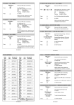
Noby-448 User Operating Manual & Log Book
Page 1 of 12
Fire Control Panel
User Operating Manual
&
Log Book
TABLE OF CONTENTS
Introduction
Keypad Operation
LED Indications
What to do in the event of a fire?
Routine Testing
Contact Details
Installation Details
Log: Event Log
Log: Test Log
Log: Engineer Service Log
Page
1
2
3
3
4
5
6
7
9
12
Introduction
This document is primarily aimed at the end-user of the Noby-448 Fire Control Panel, and should be handed over to
a Responsible Person on completion of the installation work.
The Responsible Person is the person at the site who would normally:
• prepare Fire Alarm Procedures for the premises
• ensure that all personnel are familiar with the Fire Alarm Procedures
• ensure that persons likely to operate the Fire Control Panel are familiar with
its operation, and know where the User Operating Manual is stored.
• ensure that all detectors and call-points remain free from obstruction
• routinely test the Fire Alarm System
• contact the Installation/Service Company in the event of a fire, system
fault or false alarms
• ensure that the Fire Alarm System is regularly serviced
• maintain a log book of all activities related to the Fire Alarm System
Noby-448 User Operating Manual & Log Book
Page 2 of 12
KEYPAD OPERATION
General
Each of the following functions of the fire control panel must be preceded by the 4 digit Access Code [3][6][3][6].
Successful entry of the Access Code is confirmed by the red Function LED. Pressing [5] to Quit at any time will
cause the system to revert back to normal standby mode, otherwise the system will automatically revert back after
10 seconds of inactivity.
Mute Sounders
Main external sounders switched off.
[3][6][3][6] [1]
Mute Panel
[3][6][3][6] [4]
Panel internal sounders (piezos) switched off.
System Reset
All LEDs are tested for 3 seconds.
[3][6][3][6] [5]
Quick Reset
[3][6][3][6] [1] [4] [5]
A Quick Reset is an amalgamation of the first three operations above.
Note : Main sounders & Panel sounders MUST be individually muted before a reset can is accepted.
Reset is acknowledged by a 3 second LED test.
Evacuate
[3][6][3][6] [2]
Main sounders, Panel sounders and Fire Relay are activated (provided they have not been isolated).
Zone_Isolate & Relay_Isolate
[3][6][3][6] [3]
This function is used to Isolate zones and/or the Fire Alarm Relay.
The current isolation status is displayed by any flashing yellow zone LED’s and/or the Relay_Isolate LED.
Note that scrolling down automatically wipes any pre-existing isolation status LEDs, and that it is therefore
advisable to check the whole isolation suite prior to exiting this procedure.
Key [1] to Scroll-Down and highlight the desired yellow zone LED (or the Relay_Isolate LED) for selection.
Key [3] to Toggle the selected zone (or the relay) on or off – the LED flashes when isolation is active.
Key [4] to Accept and update the current isolation status and then revert back to normal standby mode . . .OR
Key [5] to Quit and revert back to normal standby mode without updating the displayed isolation status.
Once back in normal standby mode any isolated zone (or relay) is confirmed by a flashing zone fault LED (and/or
Relay_Isolate LED). Zone_Isolate and/or Relay_Isolate operations should only be performed or authorised by the
Installation/Service Company).
Test
[3][6][3][6] [6]
This function is used to ‘one-man’ test the system.
Key [1] to Scroll-Down and highlight the zone for test.
Key [6] to Toggle the zone selected for test on or off – the yellow zone LED will flash when in test mode.
It is now possible to trigger each detector in turn on the selected zone.
The sounders are activated momentarily (provided they are not isolated) and the Zone Fire LED is latched.
The Fire Alarm Relay is not activated.
Key [5] to Quit to revert back to normal standby mode.
The system will revert back to normal standby mode after 90 seconds of panel inactivity (i.e. no keypad operations
or zone activations). Any fire alarm generated from a non-test zone will cause the system to abort the test and give
the appropriate fire response.
Noby-448 User Operating Manual & Log Book
Page 3 of 12
LED Indications
LED Indications
Continuous
Flashing
8 Zone Fire LED’s
Common Fire LED
Zone Fault LED’s
(non-latching) **
Common Fault LED
Sounder Fault LED
PSU Fault LED
CPU Fault LED
Power LED
Relay Isolate LED
Function LED
Isolate LED
Test LED
Zones alarmed
One or more zones in fire condition
First to alarm
N/A
Zone/s isolated (slow flash)
Head Removed (intermittent ‘winking’)
Fault Input terminal active, non-latching
Sounders Isolated
Fuses F1,F2,F7, Low volts & Battery
CPU watchdog warning
Mains restored
Relay isolated
N/A
One or more zones isolated
7 day fire test reminder
Zone/s in fault
Any zone fault or system fault
Sounder fault
Low voltage (< 21 volts), non-latching
Remote Bus fault
Primary supply (mains) OK. Off=mains fail
N/A
Access code successfully entered
N/A
N/A
WHAT TO DO IN THE EVENT OF A FIRE ALARM ?
User responsibilities
The Responsible Person for the fire alarm should devise written procedures for the action to be taken in the event
of a fire alarm and ensure that all other users have received sufficient training on how to operate the system
properly and that they are familiar with these procedures.
In the event of a fire
In the event of a fire alarm the fire control panel will:
• activate the Main Sounders and internal Panel Sounder.
• activate the Alarm Relay which may trigger any connected ancillary equipment.
• the LED display will indicate:
o Common Fire LED
o one or more Zone LEDs indicating the location of the fire
(the first zone to alarm is distinguishable by a flashing Zone Fire LED)
When the alarm sounds
•
CARRY OUT THE PRESCRIBED FIRE ALARM PROCEDURE
Silencing the panel
Only after the prescribed Fire Alarm Procedures have been carried out should you silence the audible sounders.
• Mute Sounders
[3][6][3][6] [1 Mute Sndrs]
• Mute Panel
[3][6][3][6] [4 Mute Panel]
To re-sound the alarm
Once silenced the sounders can be manually re-activated:
• Evacuate
[3][6][3][6] [2 Evacuate]
Resetting the system
Only perform a System Reset once the cause of the alarm has been established.
• Quick Reset
[3][6][3][6] [1] [4] [5]
If the original cause of the alarm still exists or has not cleared then the alarm will immediately re-sound.
Noby-448 User Operating Manual & Log Book
Page 4 of 12
ROUTINE TESTING
The Fire Alarm System should be periodically tested by the Responsible Person to ensure that it remains fully
functional at all times.
Daily
Check the panel for normal operation.
The green Power LED should be lit.
The Isolate LED may be flashing in which case one or more yellow zone fault LEDs will also be flashing. **
The Relay_Isolate LED may be flashing.**
Any other fault indication should be recorded in the Event Log and the Installation/Service Company informed.
**
Zone_Isolate and/or Relay_Isolate operations should only be performed or authorised by the Installation/
Service Company).
Weekly
Operate at least one manual call point or detector to ensure correct operation of the Noby-448 Control Panel.
If possible, choose a different device to trigger the Fire Alarm System each week, by rotation, such that the whole
system is eventually tested over a period of time.
A record of the test should be kept in the Test Log.
The Installation/Service Company may have configured a Weekly Test Reminder option, which will flash the Test
LED and sound an intermittent bleep when a test is due. This reminder will be automatically reset after a test has
been carried out.
Quarterly
Every three months the Installation/Service Company should check the Fire Alarm System:
•
•
•
•
•
•
Check the log book entries and confirm that any remedial action has been taken.
Check the battery and its connections.
Remove mains supply and check that the battery is capable of supplying the alarm sounders.
Operate at least one call point or detector in each zone to test the fire alarm as per above.
Perform a visual inspection of the fire alarm system for any alterations or obstructions.
Issue a certificate of testing.
Annually
Every twelve months the Installation/Service Company should check the Fire Alarm System. This check is similar to
the quarterly check except that every device on the system should be checked for operation
Noby-448 User Operating Manual & Log Book
Page 5 of 12
CONTACT DETAILS
Site Name
______________________________________________
Site Address
______________________________________________
______________________________________________
______________________________________________
______________________________________________
Responsible Person
___________________________
Installer Name
______________________________________________
Installer Address
______________________________________________
______________________________________________
______________________________________________
______________________________________________
Tel No
___________________________
Fax No
___________________________
Emergency Contact
Office Hours
______________________________________________
24 Hour
______________________________________________
Noby-448 User Operating Manual & Log Book
Page 6 of 12
INSTALLATION DETAILS
Zone Circuit Details
Location
Detectors
Type
Qty
Call
Points
Comments
1
2
3
4
5
6
7
8
Sounder Circuit Details
Location
Sounders
Type
1
2
3
4
5
6
7
8
Comments
Qty
Noby-448 User Operating Manual & Log Book
Page 7 of 12
EVENT LOG
Date
Zone / Device
Event
Action
Signature
Noby-448 User Operating Manual & Log Book
Page 8 of 12
EVENT LOG
Date
Zone / Device
Event
Action
Signature
Noby-448 User Operating Manual & Log Book
Page 9 of 12
TEST LOG
Date
Zone / Device
Comment
Signature
Noby-448 User Operating Manual & Log Book
Page 10 of 12
TEST LOG
Date
Zone / Device
Comment
Signature
Noby-448 User Operating Manual & Log Book
Page 11 of 12
TEST LOG
Date
Zone / Device
Comment
Signature
Noby-448 User Operating Manual & Log Book
Page 12 of 12
ENGINEER SERVICE LOG
Date
Inspection / Work Done
Signed