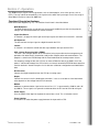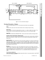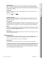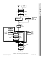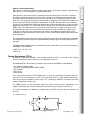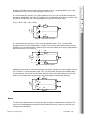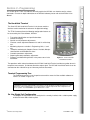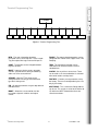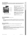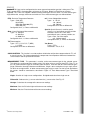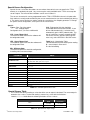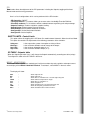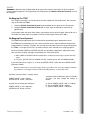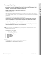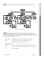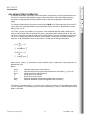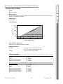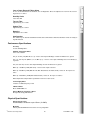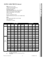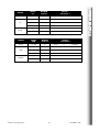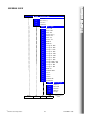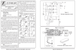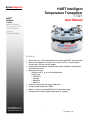
1
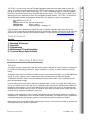
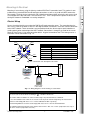
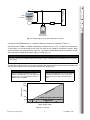
SmarResearch
HART Intelligent
Temperature Transmitter
TT421
TechnologySource
HART®
Fieldbus
Profibus
Intrinsic Safety
Configuration Tools
Semiconductors
Training
Custom Design
User Manual
Features
•
•
•
•
•
•
•
•
Smart two-wire, 4-20 mA loop power transmitter with HART communication
Measures temperature using resistive sensors (RTD’s), thermocouples,
sensors with resistance or mV outputs
Linearization international standards and custom calibration according to
Callendar Van Dusen
Measurement Type
- Single sensor; 2, 3, or 4 wire configurations
- Dual Sensor
* Differential
* Average
* Maximum
* Minimum
Extensive transmitter and sensor diagnostics
Factory tested isolation for 1500V
Mounts in industry standard DIN Form B connection head
Configured to customer specifications prior to shipping
Visit the SmarResearch
technology center at:
©
www.smarresearch.com
Smar Research Corporation
1
TT421MAN - 0109
II 2G EEx ia IIC T5 / T6
EN50014:1997+A1-A2 General Requirements
EN50020:2002
Intrinsic safety “i”
EN50284:1999
Equipment Group II Category 1G
It is the purpose of this document to explain the setup, installation, operation and maintenance of the
TT421 as well as provide all accompanying technical specifications and data. For the most up to date information on this product and other Smar Research products, visit our website www.SmarResearch.com.
Table of Contents
Section
1)
2)
3)
4)
5)
Page
Mounting & Electrical
Operation
Programming
Maintenance & Troubleshooting
Technical Data & Specifications
2
6
12
22
25
Section 1 - Mounting & Electrical
General
The overall accuracy of temperature and other measurements depends on several variables. Although the
transmitter has outstanding performance, proper installation is essential, in order to maximize its performance.
Among the factors which may affect transmitter accuracy, environmental conditions are the most difficult to
control. There are, however, ways of reducing the effects of temperature, humidity and vibration.
Temperature fluctuation effects can be minimized by locating the transmitter in areas protected from extreme environmental changes.
In hot environments, the transmitter should be installed to avoid, as much as possible, direct exposure to
the sun. Installation close to lines and vessels subjected to high temperatures should also be avoided. For
temperature measurements, sensors with cooling-neck can be used or the sensor can be mounted separated from the transmitter housing. Use of sun shades or heat shields to protect the transmitter from external heat sources should be considered, if necessary.
Humidity is fatal to electronic circuits. In areas subjected to high relative humidity, the device should be installed within an isolated panel, which will protect it from the elements. The electronic circuit is protected by
a humidity proof coating, but frequent exposures to humidity may affect the protection provided.
Measurement error can be decreased by connecting the sensor as close to the transmitter as possible and
using proper wires (see Section II, Operation).
©
Smar Research Corporation
2
TT421MAN - 0109
TT421 TOC/Section 1
The TT421 is an intrinsically safe HART enabled intelligent temperature transmitter made by Smar Research. This device measures temperature using RTD’s, thermocouples, resistance or mV input and outputs to an intrinsically safe 4-20mA current loop . The TT421 is intended to mount in a industry standard
DIN Form B connection head for easy integration with various sensors. The TT421 meets all HART Foundation physical layer requirements and is fully configurable through software. The TT421 is in compliance
with the following standards for equipment intended for use in potentially explosive atmospheres:
Mounting is fast and easy using the industry standard DIN Form B connection head. This product is compatible with any standard DIN Form B head type connections as well as any 4-20 mA HART communication network. Terminals for the intrinsically safe 4-20mA current loop and the intrinsically safe sensor circuit
are arranged on the top side of the TT421 enclosure. The T T421 is comprised of a plastic enclosure containing the electronics embedded in a casting compound.
Electric Wiring
Access the wiring block by unscrewing the DIN Form B head connection cover. The connection descriptions can be seen on the label as well as in the diagram below. Connection 5 and 6 are used for connection
to the HART network. These connections are non-polarized and thus do not require special attention regarding polarity when connecting to the HART network. Connections 1 through 4 are used for the sensor
terminals. See Figure 1.1 for more connection details. A typical connection of the TT421 being used as a
transmitter can be seen below in Fig. 1.2.
NOTE:
All cables used for connection of the TT421 to the sensor and HART network should be shielded to avoid noise.
Pin 5
Pin 6
Pin 4
Connection
Description
1
Sensor Terminals
2
Sensor Terminals
3
Sensor Terminals
Pin 1
Pin 3
Pin 2
4
Sensor Terminals
5
4-20mA HART Comm. (+/-) (non-polarized)
6
4-20 mA HART Comm. (+/-) (non-polarized)
+
250 Ohms
-
Power Supply
Fig. 1.1 – Connections and description of the TT421.
TT421
Transmitter
HPC301 Hand
Held Terminal
Fig. 1.2 – Wiring Diagram of TT421 working as a transmitter.
SPECIAL CONDITIONS FOR SAFE USE:
To ensure safe use of the TT421 according to
II 2G EEx ia IIC T5 / T6:
The TT421 shall be installed in an enclosure with a degree of protection IP20 as a minimum.
In case of installation of the TT421 in an enclosure made of plastic material or light alloy, the material of the
enclosure shall comply with clause 7.3.1 or clause 8EN 50014:1997 respectively.
Internal wiring within the enclosure shall comply with clauses 6.4.11 and 7.6.e EN 50020:2002
The following ambient temperature range applies for the TT421: -40°C ≤ Ta ≤ +75°C (temperature class T5) or
-40°C ≤ Ta ≤ +60°C (temperature class T6)
©
Smar Research Corporation
3
TT421MAN - 0109
TT421 Section 1
Mounting & Electrical
Power Supply
TT421
Transmitter
I/P
+
-
-
250 Ohms
HPC301 Hand
Held Terminal
Fig. 1.3 – Wiring Diagram for the TT421 Working as Controller
Connection of the TT421 working as a controller (Optional) should be as indicated in Figure 1.3.
Connection of the TT421 in multidrop configuration should be done as in Fig. 1.6. Note that a maximum of
15 transmitters can be connected on the same line and that they should be connected in parallel. When
many transmitters are connected to the same line, calculate the voltage drop through the 250 Ohm resistor
and verify that the voltage of the power supply is enough (Fig 1.4).
ATTENTION:
For proper operation, the HPC301 Hand-Held Terminal requires a minimum load of 250 Ohm between it and the
power supply.
The HPC301 Hand-Held Terminal can be connected to the communication terminals of the transmitter or at
any point of the signal line by using a HART interface with alligator clips.
NOTE:
IMPORTANT:
Make sure that the transmitter is operating
within the operating area as shown on the load
diagram (Fig. 1.6). Communication requires a
minimum load of 250 Ohm.
When operating with dual sensors, both cannot
be grounded. A minimum of one sensor must
NOT be grounded for proper operation of the
TT421.
1650
LOAD (Ohms)
1500
ea
Ar
g
n
ti
era
Op
1000
500
4 - 20mA and digital communication
250
4 - 20mA only
12
17
20
30
40
45
Power Supply (Volts)
Fig. 1.4 – Load Curve
©
Smar Research Corporation
4
TT421MAN - 0109
TT421 Section 1
+
+
2
3
4
1
2-Wire RTD or
Ohm input
1
2
3
+
2
3
4
1
3-Wire RTD or
Ohm input
4
1
2
3
2
3
TT421 Section 1
1
4
4-Wire RTD or
Ohm input
4
1
2
3
4
+
Thermocouple or
Millivolt input
-
+
Differential, Min, Max,
Average in either RTD
or Ohm input
-
Differential, Min, Max,
Average in either
Thermocouple or
Millivolt input
+
+
-
+
TT421
Transmitter
#1
-
+
....
TT421
Transmitter
#2
250 Ohms
Min.
-
TT421
Transmitter
#15
-
Power Supply
Fig. 1.5 – Sensor Wiring
HPC301 Hand
Held Terminal
Fig. 1.6 – Wiring Diagram for the TT421 in Multidrop Configuration
©
Smar Research Corporation
5
TT421MAN - 0109
The TT421 accepts signals from mV generators such as thermocouples, or resistive sensors such as
RTD’s. The only criteria for compatibility is the signal must be within the input range. For mV, the range is 50 to 500 mV and for resistance, 0-2000 Ohm.
Functional Description-Hardware
Refer to the block diagram (Fig. 2.1). The function of each block is described below.
MUX-Multiplexer
The MUX multiplexes the sensor terminals to the signal conditioning section ensuring that the
voltages are measured between the correct terminals.
Signal Conditioner
Its function is to apply the correct gain to the input signals to make them suit the A/D - converter.
A/D Converter
The A/D converts the input signal to a digital format for the CPU.
Isolator
Its function is to isolate the control and data signal between the input and the CPU.
CPU - Central Processing Unit & PROM
The CPU is the intelligent portion of the transmitter, being responsible for the management and
operation of all other blocks: linearization, cold junction compensation and communication. The
program is stored in the PROM along with the linearization data for the temperature sensors.
For temporary storage of data, the CPU has an internal RAM, the data in the RAM is lost if the
power is switched off, however the CPU also has an internal nonvolatile EEPROM where data that
must be retained is stored. Examples of such data are: calibration, configuration and identification
data.
D/A Converter
Converts the digital output data from the CPU to an analog signal.
Output
Controls the current in the line feeding the transmitter. It acts as a variable resistive load whose
value depends on the voltage from the D/A converter.
Modem
Modulates a communication signal on the current line. A "1" is represented by 1200 Hz and a "0",
by 2200 Hz. These signals are symmetric and do not affect the DC level of the 4-20 mA signal.
Power Supply
Uses the power of the loop-line to power the transmitters circuit. This is limited to 3.9 mA.
Power Isolation
Its function is to isolate the power supply between the input and the CPU.
©
Smar Research Corporation
6
TT421MAN - 0109
TT421 Section 2
Section 2 - Operation
MAIN BOARD
POWER
ISOLATION
SUPPLY
LOCAL ADJUST
SUPPLY
TC
Ohm
RTD
MUX
mV
SIGNAL
CONDITIONER
A/D
CONVERTER
I
S
O
L
A
T
O
R
PROCESSING UNIT
RANGES
SPECIAL FUNCTIONS
PID (OPTIONAL)
OUTPUT CONTROL
SERIAL COMMUNICATION
HART PROTOCOL
AMBIENT
TEMPERATURE
SENSOR
D/A
CONVERTER
POWER
SUPPLY
MODEM
BELL 202
OUTPUT
DISPLAY BOARD
DISPLAY
CONTROLLER
Fig. 2.1 – TT421 Hardware Block Diagram
Functional Description - Software
Refer to the block diagram (Fig. 2.2). The function of each block is described below.
Input
Calculates the actual mV or Ohm value from the value sensed by the input circuitry.
Digital Filter
This is a low-pass filter with an adjustable time constant. It is used to smooth noisy signals. The
Damping value is the time required for the output to reach 63.2% for a step input of 100%.
Input Trim
Here, the value obtained by READING-TRIM is used to correct the transmitter for long term drift.
Standard Sensor Linearization & Compensation
Here, the mV and Ohm measurements are linearized and cold-junction compensated according to
the sensor characteristics stored in the CPU. The CPU contains data about most available standard sensors.
Special Sensor
Here, the mV and Ohm measurements may be linearized according to a customer specified linearization table stored in TABLE - X,Y. Sensor TYPE and CONNECTION is specified as well. In UNIT,
the desired engineering unit is configured. This unit is used in all communications with the transmitter. The LRL, URL and MINimum Span are used to limit the range that can be set so it is within the
table and device accuracy limits.
Ranging
This is used to set the process values corresponding to the output of 4 and 20 mA in transmitter
mode or process variable 0 and 100% in PID mode. In transmitter mode the LOWER-VALUE is the
point corresponding to 4 mA, and UPPER-VALUE is the point corresponding to 20 mA. In PID
mode, the LOWER-VALUE corresponds to PV = 0% and UPPER-VALUE corresponds to PV =
100%.
Time Generator (Optional)
Counts the time to be used by the Setpoint generator function. It may be paused by using PAUSE
and reset to zero by using RESET.
©
Smar Research Corporation
7
TT421MAN - 0109
TT421 Section 2
INPUT BOARD
PID (Optional)
First the error is calculated as SP-PV or PV-SP depending on which action (direct or reverse) is
configured in ACTION.
MV = Kp (e +
dPV
1
edt + Td .
)
∫
Tr
dt
Auto/Manual (Optional)
The Auto/Manual mode is toggled in INDIC. In Manual, MV may be adjusted by the user in the
INDIC option. The POWER-ON option is used here to determine in which mode the controller
should be on power-up.
Limits (Optional)
This block makes sure that the MV does not go beyond its minimum and maximum limits as established by the HIGH-LIMIT and LOW-LIMIT. It also makes sure that the Rate-of-Change does not
exceed the value set in OUT-CHG/S. These values are adjusted in the SAFETY LIMITS option.
Output
Calculates the current proportional to the process variable or Manipulated variable to be transmitted to the 4-20 mA output, depending if the PID Module is ON or OFF. This block also contains the
constant current function configured in OUTPUT.
Current Trim
The 4 mA-TRIM and 20 mA-TRIM are used to make the transmitter current comply with a current
standard, should a deviation arise.
Temperature Sensors
The TT421, as previously explained, accepts several types of sensors. The TT421 is specially designed for temperature measurement using thermocouples or thermoresistances (RTDs).
Some basic concepts about these sensors are presented below.
Thermocouples
Thermocouples are the most widely used sensors in industrial temperature measurements.
Thermocouples consist of two wires made from different metals or alloys joined at one end, in what
is called a measuring junction. The measuring junction should be placed at the point of measurement. The other end of the thermocouple is open and connected to the temperature transmitter.
This point is called the reference junction or cold junction. For most applications, the Seebeck effect is sufficient to explain thermocouple behavior.
©
Smar Research Corporation
8
TT421MAN - 0109
TT421 Section 2
Setpoint (Optional)
In this block, setpoint tracking may be activated in SP-TRACKING. The setpoint is adjusted in
INDIC. The setpoint may also be generated automatically by turning the SP-GENERATOR ON.
When running, the setpoint generator will ramp and dwell the setpoint according to a table that can
be configured in SP-TABLE.
TT421 Section 2
C TEMP
SENSOR
OHM / mV
INPUT
DIGITALFILTER
DAMPING
INPUT TRIM
SPAN
STANDARD SENSOR
LINEARIZATION & CJ
COMPENSATION
SPECIAL SENSOR
TYPE/CONNECTION
UNIT
TABLE
LRL / URL / MIN
PV
RANGING
URV
LRV
BURNOUT
TIME
GENERATOR
T min
SP
SP TRACKING
SP GENERAL
SP TABLE
BUMPLESS A/M
SETPOINT
ALARM
PID
AUTO/MANUAL
ERROR %
LIMITS
PID BLOCK (OPTIONAL)
ACTION
KP, TR, TD
ACTION – 0
ACTION – 1
ACTION – 2
LIMIT – 1
LIMIT – 2
A/M
MV
POWER-ON
SAFETY-OUT
HIGH
LOW
OUT
MV FEEDBACK
OP-MODE
PID
XMTR
OUT %
OUTPUT
CONST
mA
CURRENT TRIM
4 – 20 mA
Fig. 2.2 – TT421 Software Function Block Diagram
©
Smar Research Corporation
9
TT421MAN - 0109
When two wires of dissimilar metals are joined on one end, and left open on the other, a temperature difference between the two ends will result in a voltage since the potentials generated by the
dissimilar materials are different and do not cancel each other out. Two important things must be
noted. First: the voltage generated by the thermocouple is proportional to the difference between the
measuring-junction and the cold junction temperatures. Therefore the temperature at the reference
junction must be added to the temperature derived from the thermocouple output, in order to find the
temperature measured. This is called cold junction compensation, and is done automatically by the
TT421, which has a temperature sensor at the sensor terminals for this purpose. Secondly, if the
thermocouple wires are not used all the way to the terminals of the transmitter (e.g. copper wire is
used from sensor-head or marshalling box) new junctions with additional Seebeck effects will be
created and ruin the measurement in most cases, since the cold-junction compensation will be done
at the wrong point.
The relation between the measuring junction temperature and the generated millivoltage is tabulated
in thermocouple calibration tables for standardized thermocouple types, the reference temperature
being 0oC.
Standardized thermocouple which are commercially used, whose tables are stored in the memory of
the TT421, are the following:
NBS (B, E, J, K, N, R, S, T)
DIN (L, U)
Thermo Resistances (RTDs)
Resistance Temperature Detectors, most commonly known as RTD's, are based on the principle
that the resistance of a metal increases as its temperature increases.
Standardized RTDs, whose tables are stored in the memory of the TT421, are the following:
JIS [1604-81] (Pt50 & Pt100)
IEC, DIN, JIS [1604-89] (Pt50, Pt100 & Pt500)
IEC (Pt1000)
GE (Cu 10)
DIN (Ni 120)
For a correct measurement of RTD temperature, it is necessary to eliminate the effect of the resistance of the wires connecting the sensor to the measuring circuit. In some industrial applications,
these wires may be hundreds of meters long. This is particularly important at locations where the
ambient temperature changes a lot.
The TT421 permits a 2-wire connection which may cause measuring errors, depending on the
length of connection wires and on the temperature to which they are exposed (see Fig. 2.3).
In a 2-wire connection, the voltage V2 is proportional to the RTD resistance plus the resistance of
the wires.
V2 = [RTD + 2x R] x I
©
Smar Research Corporation
Fig. 2.3 – Two-Wire Connection
10
TT421MAN - 0109
TT421 Section 2
How the Thermocouple Works
When there is a temperature difference along a metal wire, a small electric potential, unique to every
alloy, will occur. This phenomenon is called Seebeck effect.
In a 3-wire connection, terminal 3 is a high impedance input. Thus, no current flows through that
wire and no voltage drop is caused. The voltage V2-V1 is independent of the wire resistances since
they will be canceled out, and is directly proportional to the RTD resistance alone.
V2-V1 = [RTD + R]x I - Rx I = RTDx I
Fig. 2.4 – Three-Wire Connection
In a 4-wire connection, terminals 2 and 3 are high impedance inputs. Thus, no current flows
through those wires and no voltage drop is caused. The resistance of the other two wires are not
interesting since no measurement is done on them. Hence the voltage V2 is directly proportional to
the RTD resistance. (V2 = RTD x I).
Fig. 2.5 – Four-Wire Connection
A differential connection is similar to the two-wire connection and gives the same problem (see Fig.
2.6). Terminal 3 is a high impedance input. Thus, no current flows through and no voltage drop is
caused. However, the resistance of the other two wires will be measured and do not cancel each
other out in the temperature measurement, since linearization will affect them differently.
Fig. 2.6 – Differential Connection
Alarm
The alarms are software alarms and have no external contacts available on the transmitter. The
alarms are acknowledged by using the HPC301 Hand-Held Terminal, which can also view and
configure them individually.
©
Smar Research Corporation
11
TT421MAN - 0109
TT421 Section 2
In order to avoid the resistance effect of the connection wires, it is recommended to use a 3-wire
connection (see Fig. 2.4) or a 4-wire connection (see Fig. 2.5).
This section of the TT421 User Manual will briefly explain the HPC301 user interface and its various
commands. For more in-depth information on the HPC301 software please refer to the HPC301 User
Manual.
The Hand-Held Terminal
The Smar HPC301 Hand-Held Terminal is the human machine
interface used to maximize the advances of digital technology.
The TT421 firmware allows the following configuration features to
be accessed by the Palm software, HPC301:
•
•
•
•
•
•
•
•
•
Transmitter identification and specification data.
Remote re-ranging.
Special sensor parameter adjustments.
Constant current adjustment between 3.6 and 21 mA for loop
test.
Monitoring of process variable in Engineering Units, % and
mA.
Controller monitoring for Setpoint, Process Variable, Manipulated Variable and Auto/Manual status.
Controller parameters adjustment.
Setpoint generator parameters adjustment.
Diagnosis and determining of faults in the processor or in the
transmitter.
Figure 3.1 - Smar’s HPC301
Hand-Held Terminal
The operations which take place between the HPC301 Hand Held Terminal and the transmitter do not interrupt the measurement, and do not disturb the output signal. The HPC301 Hand Held Terminal can be
connected on the 4-20 mA line up to 2 km away from the transmitter.
Terminal Programming Tree
The Programming tree is a tree-shaped structure with a menu of all the available software resources, as shown in Figure 3.2.
WARNING:
All transmitters are factory configured with no passwords. To avoid operation by nonauthorized persons in some
critical levels of the Programming Tree, it is recommended to configure all passwords and configuration levels
prior to operation. See "PASSWORD" option in Maintenance section.
On Line Single Unit Configuration
To configure the transmitter on line, certify that it is correctly installed, with a suitable power supply
and the minimum 250 Ω load required.
©
Smar Research Corporation
12
TT421MAN - 0109
TT421 Section 3
Section 3 - Programming
TT421
Info
Conf
Maint
Sensor
PID
Monit
Range
Trim
Alarm
Factory
Multidrop
Fig. 3.2 - Terminal Programming Tree
INFO - The main information about the
transmitter can be accessed here. These include
Tag, Descriptor, Message, Date and Unique ID.
RANGE - The output related parameters can be
configured here: Lower Value, Upper Value, Unit,
Damping.
CONF - The burnout can be changed between
High or Low here.
TRIM - The transmitter indication can be
calibrated to an Ohm/mV and/or a current
standard here.
MAINT - Loop tests, device resets, operation
counters, password level setting and ordering
codes can all be accessed here.
SENSOR - Here the TT421 input can be
configured to the sensor type and connection
type that is being used.
PID - All control parameters may be adjusted and
monitored here.
MONIT - Allows the user to monitor 4 of the
transmitters dynamic variables and output
current.
©
Smar Research Corporation
ALARM - Set any of the 3 alarms here. These
can be used as an alert method that is activated
with certain actions and trip levels.
FACTORY - Contains preset parameters set by
the factory. These are not adjustable by the user,
only by the factory.
MULTIDROP - This is where the Polling Address
can be set. This assigns a value for the device (015) within the HART network when there are
several transmitters.
13
TT421MAN - 0109
TT421 Section 3
Terminal Programming Tree
The main information about the transmitter can be accessed here. These include Tag, Descriptor, Message,
Date and Unique ID. There is also a device info screen that contains additional important device information.
This includes Manufacturer, Device Type, Device Serial Number and software and hardware revision
numbers among others.
.
TAG: Eight character alphanumeric field for
identification of the transmitter.
INFO
INFO
TAG
8 CHARACTERS
DESCRIPTOR
16 CHARACTERS
DATE MODIFIED
MM / DD / YYYY
MESSAGE
32 CHARACTERS
UNIQUE ID
Fig. 3.3 – Terminal Information Tree
DESCRIPTOR: 16-character alphanumeric field
for additional identification of the transmitter. May
be used to identify service or location.
DATE MODIFIED: The date may be used to
identify a relevant date as the last calibration, the
next calibration or the installation. The date is
presented in the form of Month, Day, Year.
MESSAGE: 32-character alphanumeric field for
any other information, such as the name of the
person who made the last calibration, some
special care to be taken, etc.
UNIQUE ID: Readable only information.
CONF - CONFIGURATION
The burnout can be changed between High or Low here.
Burnout
Burnout can occur when the sensor reading is out of range or open. In these cases, the transmitter can
be set to output the maximum limit of 21 mA by setting the burnout to High, or the minimum limit of 3.6
mA by setting the burnout to Low. If the TT421 operates as a controller, the safety-out in PID should be
used instead.
MAINT - MAINTENANCE
Loop tests, device resets, operation counters, password level setting and ordering codes can all be
accessed here.
Here is a description of features which can be performed in the MAINTENANCE function:
- Device Reset: Power ON/OFF
- Loop Test: The output can be set to any desired value between 3.6 and 21 mA regardless of input.
- Operations Counter: This feature allows you to view the number of changes done to the Zero Span,
Fixed Current, Trim (4 & 20mA), Burnout, Sensor, Auto/Manual, and Multidrop
- Passwords: Set passwords and access levels
- Ordering Code: Contains the factory ordering code of the device.
©
Smar Research Corporation
14
TT421MAN - 0109
TT421 Section 3
INFO - INFORMATION
Here the TT421 input can be configured to the sensor type and connection type that is being used. The
TT421 supports RTD’s, thermocouples, resistance or mV inputs. Below is a list of the sensor types
supported. The TT421 also supports 5 different measurement types for RTD, Ohm, TC or mV sensor types:
single, differential, average, maximum and minimum. These measurement types are defined below.
RTD: Resistive Temperature Detectors
Types: Cu10 (GE)
Ni120 (DIN)
Pt50, 100, 500,1000 (IEC)
Pt50, 100 (JIS)
Configurable for 2, 3, 4 wires or differential
Ohm: Linear Resistance Measurement
Types: 0 - 100 Ohm
0 - 400 Ohm
0 - 2000 Ohm
Configurable for 2, 3 ,4 wires or differential
TC: Thermocouples
Types: B, E, J, K, N, R, S, T (NBS)
L, U (DIN)
Configurable for 2 wires or differential
mV: Linear Voltage Measurement
Types: -6 - 22 mV
-10 - 100 mV
-20 - 500 mV
Configurable for 2 wires or differential
Special: Special Sensor is used for special
sensors, e.g., load cells or resistive position
indicators. It turns the TT421 into a
transmitter for mass, volume, position, etc.
Types - Ohm - Resistive output
mV - Voltage output
Configurable for 2, 3, 4 wires or differential
Van Dusen:
Types: RTD’s
Parameters: RO, A, B, C
COLD JUNCTION - This function is used to enable or disable the cold junction compensation for TC, mV
or special sensors. This feature automatically compensates for temperature differences between the
sensor location and the junction box location.
MEASUREMENT TYPE - This parameter is used to set the measurement type for the selected sensor.
This effects the resulting primary variable value. Only when using a sensor of type RTD, Ohm, TC, or
mV, will a Measurement Type be selectable from the menu. There are total of 5 measurement types,
Single, Differential, Average, Maximum and Minimum. Single is to be used when using a single sensor.
For dual sensor applications, all other measurement types may be used. For dual sensor applications
the sensors should be connected as described in Figure 1.5. Each Measurement Type is described
below.
Single - Used for all single sensor configurations. Straightforward value from single sensor.
Differential - Subtracts the (+) sensor value from the (-) sensor value. See Fig. 1.5.
Average - Calculates the average of the two sensor readings.
Maximum - Sets the PV to the higher of the two sensor readings.
Minimum - Sets the PV to the lower of the two sensor readings.
©
Smar Research Corporation
15
TT421MAN - 0109
TT421 Section 3
SENSOR
Special Sensor is a function that allows sensors whose characteristics are not stored in the TT421
memory as a standard to be used. Any sensor may be used, provided that the TT421 can accept the
sensors output. The mV and Ohm limitations can be seen in table 3.2.
The sensors characteristic can be programmed into the TT421's EEPROM in form of a 16-point table.
Such tables are usually made available by the sensor manufacturer but can also be obtained by testing
it. The special sensor function can not be used at the same time as the Setpoint generator. To change
the special sensor configuration, select special in the sensor menu.
Special:
Types - Ohm - Resistive output
mV - Voltage output
Configurable for 2, 3, 4 wires or differential
Unit - Engineering Unit that should be
associated with the measured variable. If one
of over 100 standard units is selected, it will
automatically get its HART protocol code. This
way all supervisory systems supporting HART
can access the unit. Should a special unit be
necessary, select SPECIAL in the UNIT menu.
LRL - Lower Range Limit
The minimum lower value that the software will
be configured to read.
URL - Upper Range Limit
The maximum upper value that the software will
be configured to read.
Table (x, y) - Linearization Table
Table that relates the measured input to reading
X = sensed input in Ohm or mV
Y = desired reading
Min - Minimum Span
The minimum Span that should be configurable,
in reading value, not sensed input.
VARIABLES
PRESSURE
VOLUMETRIC FLOW
UNITS
inH2O, InHg, ftH2O, mmH2O, mmHg, psi, bar, mbar, g/cm2, Pa, KPa, Ton, ATM
ft3/m, gal/m, I/min, Gal/m, m3/h, gal/s, I/s, MI/d, ft3/s, ft3/d, m3/d, Gal/h, Gal/d, ft3/h, m3/m,
bbl/s, bbl/m, bbl/h, bbl/d, gal/h, Gal/s, I/h, gal/d
SPEED
ft/s, m/s, m/h
TEMPERATURE
o
C, oF, oR, K
VOLTAGE
mv, v
VOLUME
gal, l, Gal, m3, bbl, bush, Yd3, ft3, In3
LEVEL
ft, m, in, cm, mm
TIME
min, sec, h, dia
MASS
gram, kg, Ton, lb, Shton, LTon
MASS FLOW
g/s, g/min, g/h, kg/s, kg/m, kg/h, kg/d, Ton/m, Ton/h, Ton/d, lb/s, lb/m, lb/h, lb/d, Ton/d
DENSITY
SGU, g/cm3, kg/m3, g/ml, kg/l, g/I, TWARD, BRIX, Baum H, Baum L, API, % So/w, % Solv, Ball
MISC.
Ohm, Hz, mA, %, pH, µs, cPo
SPECIAL
5 characters
TABLE 3.1 - Available Special Sensor Unit
Special Sensor Table
This is where the desired reading as a function of the sensor output is tabulated. The sensor output is
entered as the x-value. The desired reading is entered as y-value with the limitations:
-19999 < = Y < = +19999. Note the following limitations for the x-values:
CONN. TYPE
2, 3 or 4
WIRE
DIFFERENTIAL
(each input)
Ohm
0 to 2000
0 to 1000
mV
-20 to 500
-10 to 250
Table 3.2 - Special Sensor Input Range
©
Smar Research Corporation
16
TT421MAN - 0109
TT421 Section 3
Special Sensor Configuration
This function allows the adjustment of the PID parameters including the Setpoint, toggling of the Auto/
Manual mode and the tuning parameters.
Here is a list of configurations which can be performed in the PID function:
- PID Controller: ON/OFF
- Tuning Parameters: This feature allows you to enter values into the Kp, Tr and/or Td fields.
- PV and SP readouts: E.U. check box switches readout between engineering unit and percentage.
- Setpoint Tracking: Enables or disables setpoint tracking.
- Control Action: Select between Direct or Reverse.
- Control Mode: Select between Automatic or Manual.
- Configure MV: Set the Manipulated Variable.
- Configure SP: Set the Setpoint.
SAFETY LIMITS - Control Limits
This option allows the toggling of the SP Power On mode between Automatic, Manual and Last Mode.
This option also enables the adjustment of the following parameters of the controller:
Safety out Out Chg/s Low Limit High Limit -
Is the output after a power interruption or during a failure.
Is the maximum allowable rate-of-change of the output.
Is the minimum allowable output (in %).
Is the maximum allowable output (in %).
SP-TABLE - Setpoint table
When the Setpoint generator is on, it will change the Setpoint automatically according to a table (recipe).
To configure this table select SP-TABLE in the menu.
MONIT - MONITORING
This function allows simultaneous monitoring of 4 of the transmitters dynamic variables and output current
on the display of the HPC301 Hand Held Terminal. To activate it, select MONIT in the main menu.
The display will show:
OUT
MV
PV
TAmb
PV%
SP%
SP TIME
ER%
©
-
Smar Research Corporation
Shows output in mA.
Shows output in %.
Shows Process Variable in the selected engineering unit.
Shows ambient temperature in deg C.
Shows Process Variable in %.
Shows Setpoint in %.
Shows Setpoint in the selected engineering unit.
Shows the Setpoint generator time in min.
Shows deviation between SP% and PV%.
17
TT421MAN - 0109
TT421 Section 3
PID
This function determines the 4-20 mA output of the transmitter. Here the transmitter can be re-ranged or
have the damping adjusted. The Engineering Units displayed on the HPC301 Hand Held Terminal can also
be changed.
Re-Ranging The TT421
To re-range a transmitter is to change the input values related to 4 mA and to 20 mA. There are two
ways to do it with the TT421:
1 - Using the HPC301 Hand Held Terminal (from keyboard) where signal input is not required.
2 - Using the HPC301 Hand Held Terminal with an input signal or calibrator as reference (to
applied input).
In transmitter mode, the Lower Value always corresponds to 4 mA and the Upper Value to 20 mA. in
PID mode, the Lower Value corresponds to PV=0% and the Upper Value to PV=100%.
Re-Ranging From Keyboard
The TT421 may be adjusted to give 4 and 20 mA corresponding to given temperature values.
The TT421 has the expected input, from several standard sensors output at different temperatures,
programmed in its memory. Therefore, the zero and span input does not have to be generated when
the TT421 is re-ranged, thus there is no need to connect it to a calibrator for re-ranging purposes.
Observe that both LOWER and UPPER VALUES are completely independent. Adjustment of one
does not affect the other. Although, the following rules must be observed:
a) Both LOWER and UPPER VALUES should not be smaller than lower range or greater than high
range.
b) The span, [(UPPER VALUE)-(LOWER VALUE)], should be greater than the MINIMUM SPAN.
If you intend to reverse a signal, i.e., to have the UPPER VALUE smaller than the LOWER VALUE,
proceed as follows:
Make the Lower Value as close to the Upper Value as possible or vice-versa, observing the minimum
span allowed , set the Upper Value to the desired setting and then, set the Lower Value.
Example: If the transmitter is ranged, so that:
considering that the Minimum Span IEC Pt100 is
10 Ohms, you must change the settings as
follows:
LOWER VALUE 4 mA = 0 Ohms
UPPER VALUE 20 mA = 100 Ohms
and you want to change the settings to:
a) Set the LOWER VALUE = 90, i.e. (100-10)
b) Set the UPPER VALUE = 0 Ohms
c) Set the LOWER VALUE = 100 Ohms
LOWER VALUE 4 mA = 100 Ohms
UPPER VALUE 20 mA =0 Ohms
©
Smar Research Corporation
18
TT421MAN - 0109
TT421 Section 3
RANGE
This is the most conventional way to re-range or to calibrate a transmitter. Apply the input to which
you want to set the 4 mA/PV=0% point. If, through the HPC301 Hand Held Terminal, you tell the
transmitter that this is the 4 mA/PV=0% point, this input is set as the Lower Value and the span is
maintained. The same procedure is applied for the Upper Value.
Example: A transmitter with resistance input is ranged, so that:
LOWER VALUE 0 Ohm
UPPER VALUE 100 Ohm
After installation, the potentiometer residual may give a reading of, for instance, 5 Ohm when the resistive position indicator is at zero. The zero suppression is easily accomplished with the re-ranging
with reference.
The Lower Value is the transmitter reading of the applied input.
The Upper Range Value may be changed in the same way. As mentioned before, the transmitter
reading in Engineering Units of the 4-20 mA points may differ slightly from your plant standard.
Although the 4-20 mA setpoints will operate properly within these applied settings, the transmitter
reading, in Engineering Units, may indicate a slightly different value.
The function TRIM-READING can be used to match the transmitter reading in Engineering Units to
your plant standard, thereby eliminating any eventual differences.
Unit
The Engineering Units of the PALM display may be changed when the option "PV UNIT", of the
RANGE function, is selected.
The following units are available;
For mV input: always mV
For Ohm input: always ohm
For thermocouple and RTD input:
degrees Celsius
degrees Fahrenheit
degrees Rankine
Kelvins
Damping
This RANGE function enables the electronic damping adjustment.
The damping may be adjusted between 0 and 32 sec.
©
Smar Research Corporation
19
TT421MAN - 0109
TT421 Section 3
Re-ranging to Applied Input
The TRIM function is used to make the reading comply with the user's resistance, voltage or current
standards.
TRIM
CURRENT
4 mA
20 mA
READING
EXIT
CORRECT?
ZERO
EXIT
GAIN
FACTORY
EXIT
CORRECT?
ACTUAL?
ACTUAL?
Fig. 3.6 – Terminal Trim Tree
ALARM
The alarm function enables/disables and configures the alarms. The actions and trip levels can be
configured independently for alarm 1 and 2. Alarm 0 is a non configurable alarm that indicates burnout.
When an enabled alarm condition is met, an on screen alert will notify the user. In addition, alarm status may
be monitored and acknowledged from alarm menu.
Acknowledge -
Acknowledges an alarm, this will turn off alarm on the transmitter.
Alarm -
Configures the operation mode of the alarm: off, low or high.
Limits -
Configures the level at which the alarm will trip in %.
Configuring Alarms
Low The alarm is activated when PV is below the trip level - decreasing signal.
©
High -
The alarm is activated when PV is above the trip level - increasing signal.
Off -
The alarm is disabled.
Smar Research Corporation
20
TT421MAN - 0109
TT421 Section 3
TRIM
ON-LINE MULTIDROP OPERATION
A multidrop connection is formed by several transmitters connected to a single communication transmission line. Communication between the host and the transmitters takes place digitally with the
transmitters analog output deactivated (XMTR mode), or with the analog output activated (PID
mode).
The communication with the transmitters and the host (PALM, DCS, Data Acquisition System or PC)
can be done with a Bell 202 Modem using Hart Protocol. Each transmitter is identified by a unique
address from 1 to 15.
The TT421 is factory set to address 0, that means a non multidrop operation mode, allowing transmitter to communicate with the Hand-Held Terminal, superimposing the communication on the 4-20
mA signal. To operate in multidrop mode, the transmitter address must be changed to a number from
1 to 15. This change deactivates the 4-20 mA analog output sending it to 4 mA (XMTR mode), or
keeps the 4-20 mA operation when the transmitter is configured for PID operating mode.
n
Ca ≥ ∑ Cj j + Cc
j =1
[
I sc ≤ min Im ax j
]
n
La ≥ ∑ Li j + Lc
j =1
[
Voc ≤ min V max j
]
When intrinsic safety is a requirement, special attention must be paid to the entity parameters allowed to that area:
Where:
Ca, La
Cij, Lij
Cc, Lc
Voc
Isc
Vmaxj
Imaxj
-
Allowable Capacitance and Inductance
Non protected internal Capacitance/Inductance of transmitter j (j = up to 15)
Cable capacitance and Inductance
Barrier open circuit voltage
Barrier short circuit current
Maximum allowable voltage to be applied to the instrument j
Maximum allowable current to be applied to the instrument j
To operate in multidrop mode, it is necessary to see which transmitters are connected on the same
line. This operation is called polling, and it is done automatically as soon as ON-LINE-MULTIDROP
option is executed.
©
Smar Research Corporation
21
TT421MAN - 0109
TT421 Section 3
MULTIDROP
General
SMAR TT421 intelligent temperature transmitters are extensively tested and inspected before delivery to the end user. Nevertheless, during their design and development, consideration was given
to the possibility of repairs by the end user, if necessary.
In general, it is recommended that the end user do not try to repair printed circuit boards. Instead
he should have spare circuit boards, which may be ordered from SMAR whenever necessary.
Diagnosis with Smar Hand-Held Terminal
Should any problem be noticed related to the transmitter's output, investigation may be carried out
by the PALM, as long as power is supplied and communication and the processing unit are operating normally.
The programmer should be connected to the transmitter in accordance with the wiring diagram
shown on Section 1, Figures 1.4, 1.5 and 1.8.
Error Messages
When communicating using the PALM the user will be informed about any problem found by the
transmitters self diagnostics.
The messages are always alternated with the information on the top line. The table below lists the
error messages. Refer to trouble shooting for more details on corrective action.
Diagnostics with the PALM
DIAGNOSTIC MESSAGES
©
POTENTIAL SOURCE OF PROBLEM
PARITY ERROR
• Excessive noise or ripple
OVERRUN ERROR
• Excessive noise or ripple
CHECK SUM ERROR
• Excessive noise or ripple
FRAMING ERROR
• Excessive noise or ripple
NO RESPONSE
• The line resistance is not in accordance with load curve.
• Transmitter not powered
• Interface not connected.
• Transmitter configured in Multidrop mode being accessed by ON LINE SINGLE UNIT.
LINE BUSY
• Other device using the line.
CMD NOT IMPLEMENTED
• Software version not compatible between PALM and transmitter.
• PALM is trying to carry out a TT421 specific command in a transmitter from another
manufacturer.
TRANSMITTER BUSY
• Transmitter carrying out an important task.
COLD START
• Start-up or Reset due to power supply failure.
OUTPUT FIXED
• Output in Constant Mode
• Transmitter in Multi-drop mode
OUTPUT SATURATED
• Primary variable out of calibrated Span (Output current in 3.8 or 20.5 mA, XMTR mode
only
SV OUT OF LIMITS
• Cold-junction temperature sensor out of operating limits.
• Cold-junction temperature sensor damaged.
PV OUT OF LIMITS
• Input signal out of operating limits.
• Sensor damaged.
• Transmitter with false configuration
• PV out of range limits (see table)
Smar Research Corporation
22
TT421MAN - 0109
TT421 Section 4
Section 4 - Maintenance & Troubleshooting
Symptom : NO LOOP CURRENT
Probable Source of Trouble:
Transmitter Connections
• Check wiring polarity and continuity.
• Check for shorts or ground loops.
Power Supply
• Check power supply output. The voltage at the TT421 terminals must be between 12 and
45 Vdc, and the ripple less than 0.4V.
Electronic Circuit Failure
• Check the main board for defect by replacing it with a spare one.
Symptom : NO COMMUNICATION
Probable Source of Trouble:
Terminal Connections
• Check terminal interface connections.
• Check if the interface is connected to the points [COMM] and [-] or in the line between the
transmitter and the load resistor.
Transmitter Connections
• Check if connections are as per wiring diagram.
• Check line resistance; it must be equal to or greater than 250 Ohm, between the transmiter and the power supply.
Power Supply
• Check output of power supply. The voltage at the TT421 terminals must be between 12
and 45V, and ripple less than 0.4V.
Electronic Circuit Failure
• Locate the failure by alternately replacing the transmitter circuit and the interface with
spare parts.
Transmitter Address
• In On Line Multidrop item, check if the address is “0”
Symptom : CURRENT OF 21.0 mA OR 3.6 mA
Probable Source of Trouble:
Transmitter Connection
• Check if the sensor is correctly connected to the TT421 terminal block.
• Check if the sensor signal is reaching the TT421 terminal block by measuring it with a
multimeter at the transmitter-end. For mV and thermocouples test can be done with con
nected and disconnected to the transmitter.
Sensor
• Check the sensor operation; it shall be within its characteristics.
• Check sensor type; it should be the type and standard the TT421 has been configured to.
• Check if process is within the range of the sensor and the TT421.
NOTE:
A 21.0 or 3.6mA current in XMTR mode indicates burnout.
©
Smar Research Corporation
23
TT421MAN - 0109
TT421 Section 4
Troubleshooting the Transmitter
Probable Source of Trouble:
Transmitter Connections
• Check power supply voltage. The voltage at the TT421 terminals must be between 12 and
45V, and ripple less than 0.4V.
• Check for intermittent short circuits, open circuits and grounding problems.
Noise, Oscillation
• Adjust damping
• Check grounding of the transmitters housing, especially for mV and thermocouple input.
• Check the terminal block for moisture.
• Check that the shielding of the wires between sensor/transmitter and transmitter/panel is
grounded only in one end.
Sensor
• Check the sensor operation; it shall be within its characteristics.
• Check sensor type; it shall be the type and standard that the TT421 has been configured
to.
Electronic Circuit Failure
• Check the integrity of circuit replacing it with a spare one.
Calibration
• Check calibration of transmitter.
©
Smar Research Corporation
24
TT421MAN - 0109
TT421 Section 4
Symptom : INCORRECT OUTPUT
Functional Specifications
Inputs
Options see table.
Output Signal
Two-wire,4-20 mA with superimposed digital communication (HART Protocol Version 5.1/Transmitter/PollResponse mode/Common 4-20 mA).
Power Supply
12 to 45 Vdc
Load Limitation
1650
LOAD (Ohms)
1500
ea
Ar
g
tin
era
p
O
1000
500
4 - 20mA and digital communication
250
4 - 20mA only
12
17
20
30
40
45
Power Supply (Volts)
Zero and Span Adjustment
Noninteractive, by HPC301 Hand Held Terminal.
Temperature Limits
Operation:
Storage:
-40°C ≤ Ta ≤ +75°C (temperature class T5)
-40°C ≤ Ta ≤ +60°C (temperature class T6)
-40 ≤ Ta ≤ 120oC (-40 ≤ Ta ≤ 250oF)
Terminal Parameters
Pins 5,6 - non-polarized supply and signal circuit for connection to an intrinsically safe 4-20mA current loop
Voltage
Ui 28 V DC
Current
Ii
93 mA
Power
Pi 700 mW
Effective Internal Capacitance
Ci ≤ 2.2 nF
Effective Internal Inductance
Li negligible
Pins 1,2,3,4 - 2/3/4-wire measurement circuit in accordance with EEx ia I / IIC for the connection of I.S. thermocouples or RTD’s
Voltage
Uo 6.5 V DC
Current
Io 20 mA
Power
Po 30 mW
Effective Internal Capacitance
Ci ≤ 450 nF
Effective Internal Inductance
Li negligible
Maximum External Capacitance
Co ≤ 550 nF
Maximum External Inductance
Lo ≤ 20 mH
©
Smar Research Corporation
25
TT421MAN - 0109
TT421 Section 5
Section 5 - Technical Data & Specifications
In case of sensor burnout or circuit failure, the self diagnostics drives the output to 3.6 or to 21.0 mA, according to the user's choice.
Humidity Limits
10 to 100% RH
Turn-on Time
Approximately 10 seconds.
Update Time
Approximately 0.5 second.
Damping
Adjustable 0-32 seconds.
Configuration
This is done by an external Hand-Held Terminal, that communicates with the transmitter remote or locally using Hart Protocol.
Performance Specifications
Accuracy
See the following tables.
Ambient Temperature Effect
For a 10oC variation:
mV (-6...22 mV), TC (NBS: B, R, S, T): ±0.03% of the input milivoltage or 0.002 mV whichever is greater.
mV (-10...100 mV), TC (NBS: E, J, K, N; DIN: (L, U): ±0.03% of the input milivoltage or 0.01 mV whichever
is greater.
mV (-50...500 mV): ±0.03% of the input milivoltage or 0.05 mV whichever is greater.
Ohms (0...100 Ohms), RTD (GE: Cu10) : ±0.03% of the input resistance.
Ohms (0...400 Ohms), RTD (DIN: Ni: 120; IEC: Pt50, Pt100; JIS: Pt50, Pt100): ±0.03% of the input resistance.
Ohms (0...2000 Ohms), RTD (IEC: Pt500; Pt1000): ±0.03% of the input resistance.
TC: Cold-junction compensation rejection 60:1 Reference: 25,0 ±0,3oC
Power Supply Effect
±0.005% of calibrated span per volt.
Vibration Effect
Meets SAMA PMC 31.1
Electro-Magnetic Interference Effect
Designed to comply with IEC 801
Physical Specifications
Electrical Connection
Accommodates conductors up to 2.5mm2 (12 AWG)
Mounting
Industry standard DIN Form B enclosure for easy integration.
©
Smar Research Corporation
26
TT421MAN - 0109
TT421 Section 5
Loss of Input (Burnout)/Failure Alarm
TT421 Section 5
CONTROL CHARACTERISTICS (Optional)
PID
Proportional Gain: 0 to 100
Integral Time: 0.01 to 999 min/rep
Derivative Time: 0 to 999 s
Direct/Reverse Action
Lower and Upper output limits: -0.6 to +106.25%
Output rate-of-change limit: 0.02 to 600 %/s
Power-on safety output: -0.6 to +106.25%
Antireset windup
Bumpless Auto/Manual transfer
Setpoint Generator up to 16 points, up to 19999 minutes
Alarm
Dual, trip levels adjustable over entire range.
High or Low action.
Acknowledge, messaging
2, 3 OR 4 WIRES
RTD
THERMOCOUPLE
RANGE oC
RANGE oF
MINIMUM
SPAN oC
C DIGITAL
ACCURACY
RANGE oC
RANGE oF
MINIMUM
SPAN oC
o
C DIGITAL
ACCURACY
Cu10 GE
-20 to 250
-4 to 482
50
±1.0
-270 to 270
-486 to 486
50
±2.0
Ni 120 DIN
-50 to 270
-58 to 518
5
±0.1
-320 to 320
-576 to 576
5
±0.5
Pt50
IEC
-200 to 850
-328 to 1562
10
±0.2
-1050 to 1050
-1890 to 1890
10
±1.0
Pt100 IEC
-200 to 850
-328 to 1562
10
±0.2
-1050 to 1050
-1890 to 1890
10
±1.0
Pt500 IEC
-200 to 450
-328 to 842
10
±0.2
NA
NA
NA
NA
Pt50
JIS
-200 to 600
-328 to 1112
10
±0.25
-800 to 800
-1440 to 1440
10
±1.0
Pt100 JIS
-200 to 600
-328 to 1112
10
±0.25
-800 to 800
-1440 to 1440
10
±1.5
Pt1000 IEC
-200 to 300
-328 to 572
10
±0.25
-500 to 500
-868 to 500
10
±1.5
o
-1700 to 1700
-3060 to 3060
60
±1.0**
B
NBS
+100 to 1800
212 to 3272
50
E
NBS
-100 to 1000
-148 to 1832
20
±0.2
-1100 to 1100
-1980 to 1980
20
±1.0
J
NBS
-150 to 750
-238 to 1382
30
±0.3
-900 to 900
-1620 to 1620
30
±0.6
K
NBS
-200 to 1350
-328 to 2462
60
±0.6
-1550 to 1550
-2790 to 2790
60
±1.2
N
NBS
-100 to 1300
-148 to 2372
50
±0.5
-1400 to 1400
-2520 to 2520
50
±1.0
R
NBS
0 to 1750
32 to 3182
40
±0.4
-1750 to 1750
-3150 to 3150
40
±2.0
S
NBS
0 to 1750
32 to 3182
40
±0.4
-1750 to 1750
-3150 to 3150
40
±2.0
T
NBS
-200 to 400
-328 to 752
15
±0.15
-600 to 600
-1080 to 1080
15
±0.8
L
DIN
-200 to 900
-328 to 1652
35
±0.35
-1100 to 1100
-1980 to 1980
35
±0.7
U
DIN
-200 to 600
-328 to 1112
50
±0.5
-800 to 800
-1440 to 1440
50
±2.5
K DIN - IEC
-200 to 1350
-328 to 2462
60
±0.6
-1550 to 1550
-2758 to 2822
60
±1.2
S DIN - IEC
0 to 1750
32 to 3182
40
±0.4
-1750 to 1750
-3118 to 3182
40
±2.0
*
**
NA
©
DIFFERENTIAL
TYPE
SENSOR
±0.5**
Accuracy of value accessed by communication using the HPC301 Hand-Held Terminal. The 4-20 mA accuracy
is the digital accuracy ±0.03%.
Not applicable for the first 20% of the range (up to 440 oC).
Not applicable.
Smar Research Corporation
27
TT421MAN - 0109
RANGE
mV
MINIMUM
SPAN mV
Special
-50 to 500
10.00
±0.02%
or
±50 µV
-6 to 22
0.40
±0.02%
or
±2 µV
-10 to 100
2.00
±0.02%
or
±10 µV
-50 to 500
10.00
±0.02%
or
±50 µV
-28 to 28
0.40
±0.1%
or
±10 µV
-110 to 110
2.0
±0.1%
or
±10 µV
mV
DIGITAL *
ACCURACY %
mV DIF
SENSOR
RANGE
OHM
MINIMUM
SPAN mV
Special
0 to 2000
20
±0.02%
or
±0.20 Ohm
0 to 100
1
±0.02%
or
±0.01 Ohm
0 to 400
4
±0.02%
or
±0.04 Ohm
0 to 2000
20
±0.02%
or
±0.20 Ohm
-100 to 100
1
±0.08%
or
±0.04 Ohm
-400 to 400
4
±0.1%
or
±0.2 Ohm
OHM
DIGITAL *
ACCURACY %
OHM DIF
©
Smar Research Corporation
28
TT421MAN - 0109
TT421 Section 5
SENSOR
TT421 Section 5
ORDERING CODE
MODEL TT421
TEMPERATURE TRANSMITTER
CODE
Connection Type
Two wires
L2
L3
Three wires (*)
L4
Four wires
L5
2 dual wires
CODE
Sensor Type
T1
CU10 - GE
T2
NI120 - DIN
T3
PT50 - IEC
T4
PT100 - IEC (*)
T5
PT500 - IEC
T6
PT50 - JIS
T7
PT100 - JIS
T8
OHM 2K
T9
OHM 400
TA
TC Type B - NBS
TB
TC Type E - NBS
TC
TC Type J - NBS
TD
TC Type K - NBS
TE
TC Type N - NBS
TF
TC Type R - NBS
TG
TC Type S - NBS
TH
TC Type T - NBS
TI
TC Type TIPO J - DIN
TJ
TC Type TIPO K - DIN
TL
TC Type S - DIN
TM
TC Type T - DIN
TN
OHM 100
TO
SPECIAL OHM
TQ
mV 22
TR
100 mV
TS
500 mV
TT
SPECIAL MV
TU
PT1000 IEC
CODE
TT421
L3
T4
©
Smar Research Corporation
Simple (*)
E2
Differential
E3
Maximum
E4
Minimum
E5
Average
E1
TRANSMITTER
29
Measured Type
E1
* indicates factory
default
TT421MAN - 0109
TT421 Section 5
Mechanical Dimensions
Below are the mechanical dimensions of the internal transmitter and BUZ enclosure.
Fig. 3.7 – Mechanical Dimensions
Fig. 3.8 – TT421 Images
©
Smar Research Corporation
30
TT421MAN - 0109
Smar Research reserves the right to make changes to design and functionality of any product without notice. Smar Research
does not assume any liability arising out of the application or use of any product. Smar Research , Technology Source, and the
SRC logo are registered trademarks of Smar Research Corporation. The HART, Fieldbus, and Profibus Foundation logos are
trademarks of their respective owners.
Smar Research Corporation
2110 Fifth Avenue
Ronkonkoma, NY USA 11779
Tel: 631.737.3111 Fax: 631.737.3892
[email protected]
www.SmarResearch.com
©
Smar Research Corporation
31
TT421MAN - 0109