1
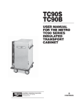
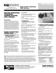
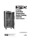
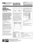
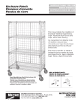
C200
Rev. 3/99
USER MANUAL
FOR THE METRO
C200 SERIES
INSULATED
HEATED CABINET
®
C
®
®
®
InterMetro Industries Corporation
Wilkes-Barre, PA 18705
570-825-2741
TABLE OF CONTENTS
SECTION
SAMPLE OF CABINET LABELING
C200 PT S-D-LH
PAGE
I. Introduction
A. Identifying Your Cabinet ............................... 1
B. Features ....................................................... 2
II. Operating Instructions
A. Reversible Doors ......................................... 2
B. Slide Rack Assemblies ................................ 2
C. Holding Module ........................................... 3
III. Cleaning Instructions
A. Removal of Interior Components ................. 4
B. Specific Cleaning Instructions ..................... 4
C. General Cleaning Instructions ..................... 4
IV. Maintenance
A. Cabinet Maintenance ................................... 4
B. Module Maintenance ................................... 4
C. Blower Motor Maintenance .......................... 4
V. Repair Parts and Procedures
A. Cabinet ......................................................... 6
B. Module ......................................................... 8
Module Replacement Procedure Chart ........ 10
VI. Wiring Schematic
A. Holding ...................................................... 12
Cabinet Series
PT = Pass-Thru
(4 doors)
Blank = Non Pass-Thru
(2 doors)
Door Hinging
Blank = Right Hand
LH = Left Hand
Thermometer Type
Blank = Analog
D = Digital
Material S = Stainless Steel
N = Aluminum
SAMPLE OF SLIDE RACK
CARTON LABELING
C4SC
Indicates Slide Racks
C4SC = 2 Pair Wire —
3" Spacing
2C8SN = 2 Pair Aluminum
Fixed on 11/2" Spacing
2CVSN = 2 Pair Aluminum
Adjustable
2C84 = 1 Pair Aluminum
Fixed on 11/2" Spacing
1 Pair Wire — 3" Spacing
2CV4 = 1 Pair Aluminum
Adjustable
1 Pair Wire — 3" Spacing
I. INTRODUCTION
A. IDENTIFYING YOUR CABINET
Your cabinet assembly has been shipped in two
cartons. The first carton contains the cabinet with
module. The other carton contains the slide racks.
There are three component numbers which you
may want to record for future reference: the cabinet
model number, the cabinet serial number and the
slide rack model number. Refer to the back of the
unit to locate the cabinet numbers. The slide rack
model number is located on the label affixed to the
ends of the rack carton. It is recommended that all
numbers be recorded in an appropriate place,
such as at the bottom of this page. AIso, please
record the cabinet model number and module
serial number on the Warranty Card found at the
back of this manual. Be sure to complete the
remainder of the Warranty Card and return it to
Metro within fifteen (15) days of delivery of the
cabinet. Once you have located and recorded
these numbers, refer to the sample numbers given
to identify the components of your C200 series
cabinet.
NOTE: Peel off any protective covering from
the exterior of the cabinet. Covering must be
removed before placing the cabinet into
service.
NOTE: Please read this manual thoroughly before using your
cabinet. If you should have questions, please contact
Metro customer service department.
1
B. FEATURES — ALL MODELS
B. SLIDE RACK ASSEMBLIES
In order to utilize your new cabinet to its
full potential, take a minute to identify the
following features which have been provided
for your convenience.
All models of slide racks are removable for
thorough cleaning.
On the inside of each cabinet are a series of
rack hangers. These hangers have two slots
for either an inboard or outboard rack
position. To remove the slide rack, grasp and
move upward until pins are free of hanger
slots. To install racks, locate pins over
hangers and lower until locked into the slots.
• The module has been placed at the top
of the cabinet for easy accessibility and
efficient operation.
• Clearly-marked control panel angled for
easy viewing and climate adjustments
without opening the door.
NOTE: For an inboard rack position, use the
slots farthest away from the inside wall of the
cabinet. For an outboard rack position, use
the slots closest to the inside wall of the
cabinet.
• Removable water pan.
• Dutch-style insulated and gasketed doors.
• Heavy-duty magnetic door latches.
C4SC — Model 4 (3" Slide Spacing — fixed)
The Model 4 Slide Rack consists of two sets
of slides. Both sets can be installed either in
an inboard or an outboard position. Also, one
set of racks can be placed in the inboard
position while the second set can be
installed in the outboard position. All pans
are to be bottom loaded regardless of rack
positioning. The following pans may be used:
• All components — doors, module,
chimneys, slide racks — removable without
tools to permit thorough, obstruction-free
cleaning.
II. OPERATING INSTRUCTIONS
A. REVERSIBLE DOOR(S)
NOTE: Only the doors on the Non Pass-Thru
Models are field reversible. The doors on your
Non Pass-Thru Cabinet can be reversed to
accommodate a right- or left-hand opening.
The cabinet has been shipped with the hinges
mounted on the right-hand side of the unit.
To reverse, follow the instructions listed below:
Inboard Hanger Position
(18" width)
17 pans — 18"x27"x25/8"
17 pans — 14"x18"x25/8"
Max. pan size: 18"x27"x25/8"
Min. pan size: 17"
Outboard Hanger Position
(20" width)
17 pans — 20"x24"x21/4"
17 pans — 20"x24"x25/8"
34 pans — 12"x20"x21/4"
34 pans — 12"x20"x25/8"
Max. pan size: 20"x27"x25/8"
Min. pan size: 19"
1. If the cabinet was in operation, allow
sufficient time for it to cool down to
comfortable level. Unlatch the doors, swing
open and lift vertically until clear of cabinet
mounted hinges. Place doors aside.
2. On the cabinet, remove the door strike plates
and hinges. Transfer them to the opposite
side of the cabinet. Install filler screws in the
original hinge and plate holes.
2C8SN—Model 28 (11/2" Spacing — fixed)
The Model 28 Slide Rack can only be
installed in the inboard hanger position.
All pans are to be lip loaded. The following
pans may be used: 34 pans — 18"x26" max.
height 13/8". Max. pan size: 18"x27"x13/8"
Min. pan size: 18"
3. On the doors, remove the round covers from
the hinges. Also remove the screws securing
the hinges to the doors.
4. Rotate the hinges 180 degrees and
reassemble.
5. On the cabinet mounted hinges, lift the white
bushing vertically and rotate 180 degrees,
then seat.
2CVSN—Model 2V (adjustable)
The Model 2V Slide Rack can be installed
in either an inboard or outboard position.
Center spacing on slides can be either 3"
or 41/2". Slides can be removed by lifting
upward and sliding rivet heads out of the
keyhole slots. To install, select spacing, insert
rivet heads into keyhole slots and push down
until locked in hole. All pans are to be bottom
loaded regardless of slide or rack
positioning.
6. Take the top door, rotate 180 degrees and
drop it onto the bottom cabinet mounted
hinges. Take the other door and drop it onto
the top mounted cabinet hinges.
7. Test doors to make sure gaskets are in
compression and the door latches hold
securely.
2
2. To introduce limited humidity, fill the 11/2-quart
capacity water pan to 1/2" from top with HOT
clean tap water. During operation, check
water level every 3 hours and refill as
necessary. The unit may be operated without
water if humidity is not desired.
With the racks in the inboard position
(18" width), the following pans may be used:
3" Slide Spacing
16 pans — 18"x26"x25/8"
32 pans — 12"x18"x25/8"
32 pans — 13"x18"x25/8"
17 pans — 14"x18"x25/8"
Max. or combined pan size: 18"x27"x25/8"
Min. pan width: 16"
Above the water pan is an adjustable vent.
By rotating the vent open even more humidity
can be introduced into the cabinet.
3. Snap POWER switch to ON. The red light will
now glow as will the yellow indicator light,
and the blower will begin circulating air.
41/ 2" Slide Spacing
11 pans — 18"x26"x41/8"
22 pans — 12"x18"x41/8"
22 pans — 13"x18"x41/8"
22 pans — 14"x18"x41/8"
Max. or combined pan size: 18"x27"x41/8"
Min. pan width: 18"
4. Turn the TEMPERATURE thermostat to
setting 10.
5. After allowing the cabinet to PREHEAT FOR
APPROXIMATELY 45 MINUTES, reduce the
thermostat setting to 8. In a room of average
temperature (72°F), this should provide
150°-170°F. Adjustments to the temperature
may be made as necessary.
With the racks in the outboard position
(20" width), the following pans may be used:
3" Slide Spacing
17 pans — 15"x20"x25/8"
34 pans — 107/8"x193/4"x25/8"
34 pans — 111/8"x20"x25/8"
17 pans — 20"x20"x25/8"
16 pans — 20"x22"x25/8"
32 pans — 12"x20"x25/8"
17 pans — 20"x24"x25/8"
Max. or combined pan size: 20"x27"x25/8"
Min. pan width: 16"
NOTE: The red light will glow as soon as the
POWER switch is switched ON and will
continue to glow until switched OFF. The
yellow indicator light will go on and off as the
thermostat cycles the heat element. The
blower will operate as long as the POWER
switch is ON. If the yellow light is not
illuminated, this indicates that the cabinet has
achieved the preset TEMPERATURE level,
NOT that the unit has been switched OFF.
41/2" Slide Spacing
11 pans — 15"x20"x41/8"
22 pans — 107/8"x193/4"X41/8"
22 pans — 111/8"x20"x41/8"
11 pans — 20"x20"x41/8"
11 pans — 20"x22"x41/8"
22 pans — 12"x20"x41/8"
11 pans — 20"x24"x41/8"
Max. or combined pan size: 20"x27"x41/8"
Min. pan width: 18"
It is not necessary at the end of the operating
day to disrupt the TEMPERATURE setting in
order to turn the unit OFF. By switching the
POWER switch to OFF, the unit is no longer
operating. By switching the POWER switch to
ON when resuming operations, the cabinet
will attain the preset level.
C. HOLDING MODULE
Equipped with a holding module, your cabinet
is designed to maintain the temperature of HOT
prepared foods. The holding module is
equipped with a thermostatically controlled
heater, a blower for air circulation and a water
pan. A POWER switch is provided with a red
light to indicate when the unit is switched ON.
A TEMPERATURE thermostat and its yellow
indicator light are also provided along with a
thermometer.
A three-wire grounded lead cord is supplied
fixed to the module.
1. With POWER switch OFF, plug lead cord into
a standard grounded 20-amp, 125-VAC
receptacle.
3
III. CLEANING INSTRUCTIONS
A. SPECIFIC CLEANING INSTRUCTIONS
1. Do not immerse the module when cleaning.
Instead, use a damp cloth and a drying
towel. Special attention should be paid to
keeping the air-inlet area and the controls
area free of dirt build-up. BE SURE TO
THOROUGHLY DRY THE MODULE BEFORE
RETURNING IT TO USE.
ALL MODELS
Your C200 series cabinet has been listed by
the National Sanitation Foundation (NSF)
which means that it has been designed and
constructed in a way that promotes a sanitary
condition, i.e. sanitary materials and easy
cleanability. To maintain a sanitary condition
and obtain the best cabinet performance,
Metro strongly suggests that the cabinet be
thoroughly cleaned on an regular basis—daily
if necessary.
B. GENERAL CLEANING INSTRUCTIONS
1. LIGHT SOIL
If routine (daily) cleaning is practiced, a mild
soap and warm water should be sufficient to
keep the unit clean.
CAUTION
2. HEAVIER SOIL
If cleaning has been postponed, solvent or
emulsion type cleaners that can be applied
with bare hands will give excellent results.
Such cleaners are available under various
brand names and detergent suppliers can
recommend materials appropriate for use on
natural and epoxy-coated aluminum and
stainless steel.
AT NO TIME SHOULD THE MODULE OR
CABINET BE WASHED OR FLOODED WITH
WATER OR LIQUID SOLUTION. NEVER
STEAM CLEAN. SEVERE DAMAGE OR
ELECTRICAL HAZARD COULD RESULT.
1. Turn off master switch.
2. Disconnect the unit from its power source.
WARNING
VI. MAINTENANCE
ALLOW THE UNIT TO COOL BEFORE
CLEANING, AS THE INTERIOR OF THE
CABINET MAY BE HOT ENOUGH TO BURN.
ALSO ALLOW THE WATER IN THE PAN TO
COOL BEFORE REMOVAL.
A. CABINET MAINTENANCE — ALL MODELS
Your C200 series cabinet has been designed
to require very little maintenance. With normal
use, cleaning is the only form of maintenance
that need be done on a regular basis.
Keeping the casters free of dirt build-up will
go a long way in prolonging their life.
3. Open the door(s) and remove the slide
racks and chimney.
4. If there is water in the pan, remove the pan
from the cabinet and empty the water.
If your cabinet is rolled over rough surfaces
or transported over-the-road, the various
threaded fasteners, i.e., screws and nuts,
should be periodically inspected and
tightened if necessary.
5. Remove the thumb screw securing each
chimney in place. Rotate each chimney
away from the cabinet wall and remove
from unit.
B. MODULE MAINTENANCE
6. To remove the module, eight thumb screws
must be removed from the ceiling of the
cabinet. First remove the water pan.
Separate the pan holder from the unit by
removing the four thumb screws.
The module in the top of your cabinet has also
been designed to require very little
maintenance. With normal use, cleaning is the
only form of maintenance that need be done
on a regular basis. Keeping vital areas such
as the air-inlet area and the controls area free
of dirt build-up will go a long way in
prolonging the life of the electrical
components. No maintenance is required on
the electrical components.
7. At each corner of the cabinet ceiling
remove the four thumb screws.
8. Lift the module from the cabinet and place
on a flat surface.
9. NOTE: Do not use abrasive cleaners. For
every cleaning method, best results are
always obtained when the cleaner and
technique are matched to the soil conditions
involved. Contact your detergent
representative to ensure the cleaning
product being used is recommended for use
on natural and epoxy coated aluminum and
stainless steel. Follow the manufacturer’s
directions on cleaners. Never mix cleaners.
10. After cleaning, replace all components.
Make sure the slide racks and chimney are
seated in the hangers correctly.
4
V. REPLACEMENT PARTS
AND PROCEDURES
A. CABINET — ALL MODELS
1. Refer to the Cabinet Replacement Parts Diagram below to identify the replacement parts.
2. Refer to the Cabinet Replacement Procedure Chart on page 6 for replacement instructions.
C200 Series Cabinet Replacement Parts Diagram
(Pass-Thru Model Shown)
REPLACEMENT PARTS LIST
Item #
Part #
Description
1
2
3
4
5
6
7A
7B
8
9
10
11
12
13
14
RPHMT2000
RPC200-8000
RPC200-8100
B5DN
B5DNB
RPC200-PAN
RPC200N-1400
RPC200N-1500
C4SC
RPC75N-1112
2CVSN
2C8SN
RP2CVN
RP2C8N
RP2C85N
Module Assembly
Top Door Assembly
Bottom Door Assembly
Caster
Caster with Brake
Water Pan
Right-hand Chimney
Left-hand Chimney
Model 4 Wire Rack
Adjustable Model 2V Slide
Model 2V Slide Rack
Model 28 Slide Rack
Model 2C4V Slide Rack (not shown)
Model 2C8VN Slide Rack (not shown)
Model 2C84N Slide Rack (not shown)
5
C200 SERIES
CABINET REPLACEMENT
PROCEDURE CHART
(Pass-Thru Model Shown)
PART TO BE REPLACED
1. Module
1. Assembly
2. Top Door
2. Assembly
3. Bottom Door
3. Assembly
4. Swivel
4. Caster
5. Caster
5. with Brake
6. Water Pan
7. Chimneys
REPLACEMENT PROCEDURE
PART TO BE REPLACED
8. Model C4SC
8. Slide Rack
For a stainless steel module using
an analog thermometer, replace with
part number RPHMT2000. For a
stainless steel module using a digital
thermometer, replace with part
number RPHMT2000D. For an
aluminum module using an analog
thermometer, replace with part
number RPHMT2000N. For an
aluminum module using a digital
thermometer, replace with part
number RPHMT2000ND.
1. See page 8, Section B, Step #1 for
module replacement procedure.
For right-hand hinging stainless
steel door, replace with part number
RPC200-8000; for left-hand hinging
stainless steel door, replace with
part number RPC200LH-8000. For
right-hand hinging aluminum door,
replace with part number
RPC200N-8000. For a left-hand
hinging aluminum door, replace with
part number RPC200NLH-8000.
1. Lift the door up off the hinges.
2. Position door and drop door hinge
down on cabinet hinge.
1. For right-hand hinging stainless
steel door; replace with part
number RPC200-8100; for lefthand stainless steel, replace with
part number RPC200LH-8100. For
right-hand hinging aluminum door,
replace with part number
RPC200N-8100. For left-hand
hinging aluminum door,
replace with part number
RPC200NLH-8100.
Replace with part number B5DN.
1. Follow instructions for item 5,
caster with brake.
Replace with part number B5DNB.
1. Lay cabinet on its side.
2. Remove hardware holding caster
to chassis.
3. Replace with new caster and
assemble with hardware.
Replace with part number
RPC200-PAN.
2 per unit. Replace with part numbers:
Right-hand chimney RPC200N-1400;
Left-hand chimney RPC200N-1500.
1. Remove thumb screw holding
chimney in place.
2. Remove chimney.
3. Replace with new chimney.
4. Secure with thumb screw.
9. Adjustable
9. Model 2V Slide
10. Model 2CVSN
10. Slide Rack
11. Model 2C8N
11. Slide Rack
12. Model 2C4V
12. Slide Rack
13. Model 2C8VN
13. Slide Rack
14. Model 2C84N
14. Slide Rack
6
REPLACEMENT PROCEDURE
Replace with part number C4SC
(consists of 1 pair of racks — 2 pair
can be used in unit)
1. To replace or add the adjustable
slide, order part number
RPC75N-1112.
Replace with part number 2CVSN
(consists of 2 pair slides and 10 pair
of adjustable slides)
1. Liff racks up off of hangers
2. Install new racks
Replace with part number 2C8SN
(consists of 2 pair slides).
1. Liff racks up off of hangers.
2. Install new racks.
Replace aluminum racks with 1 pair
of RP2CVN slides and wire racks with
part number RPC4SL-SING. Follow
instructions listed above for other
slide racks.
Replace fixed rack with 1 pair
RP2C8N. Replace adjustable racks
with 1 pair of part number RP2CVN.
Replace aluminum slides with part
number RP2C85N (1 pair) and wire
racks with RP2C8SN (1 pair).
C200 Series Door Replacement Parts Diagram
REPLACEMENT PARTS LIST
Item #
1
2
3
Part #
Description
RPC11-274
RPC06-414
RPC14-042
Door Latch
Door Gasket
Hinge
C200 SERIES
DOOR REPLACEMENT
PROCEDURE CHART
PART TO BE REPLACED
1. Door Latch
2. Door Gasket
REPLACEMENT PROCEDURE
PART TO BE REPLACED
3. Door Hinges
1. Remove screws securing latch
to door.
2. Replace with part number
RPC11-274.
Replace with part number RPC06-414.
1. Remove door from unit. Remove
screws securing inner door panel
and gasket.
2. Lift panel and gasket from door.
3. Position new gasket and inner
panel back on door.
4. Secure with hardware.
5. Mount door back on cabinet.
7
REPLACEMENT PROCEDURE
Replace with part number RPC14-042.
1. The replacement is supplied in two
parts; the lower portion mounts to
the cabinet; the upper portion
mounts to the door.
2. To replace the cabinet hinge section,
remove screws and secure new
hinge section.
3. To replace the door hinge section,
remove the hinge cap from
the body. Remove screws.
4. Pop cap from new hinge section.
Attach hinge to door. Install cap.
NOTE: When hinges are replaced
on left-hand hinging door, the white
nylon bushing must be rotated for
the self-closing feature. See Section
II A, Step No. 5.
B. MODULE
Your module has been designed to be userserviceable, assuming a basic knowledge of
the operation of electrical devices. This section
has been written to guide the user step by
step, and in layman’s terms, through the
dismantling and servicing of the module.
Before attempting to service your module, read
the appropriate Module Repair Procedures
(found elsewhere in this section) thoroughly. If
you do not understand the Repair Procedures
or prefer not to service your module yourself, or
if your warranty is still in effect, please contact
our Customer Service Department for the
factory authorized service agency nearest you.
CAUTION: IT IS IMPORTANT THAT ALL
SAFETY PRECAUTIONS PERTAINING TO
THE SERVICING OF ELECTRICAL DEVICES
BE OBSERVED AT ALL TIMES.
1. Dismantle your module for servicing per the
following instructions.
4. After servicing, be sure to verify the routing
of each wire with the appropriate wiring
schematic before installing electrical cover
and connecting module to power source. Be
sure that the thermostat sensor tube does not
contact any electrical connections.
5. Assemble components using retained
hardware, making sure that no wires
are pinched between the cover and the
module platform.
NOTE: To replace the Thermostat Knob, it is not
necessary to dismantle the module.
a. Make sure the power cord is not plugged
into an outlet. Be certain that the module and
any water in the water pan has cooled to a
temperature safe for handling.
b. To remove the module, eight thumb screws
must be removed from the ceiling of the
cabinet. First remove the water pan.
Separate the pan holder from the unit by
removing the four thumb screws.
c. At each corner of the cabinet ceiling remove
the retaining four thumb screws.
d. Lift the module from the cabinet and place
on a flat surface.
e. Unfasten the electrical cover by removing the
screws along the bottom sides and rear of the
module. Retain this hardware for re-assembly.
f. Lift the cover up off the module. Thread cord
through bushing. IF NECESSARY TO
RECONNECT THE OPENED MODULE TO A
POWER SOURCE, PRACTICE EXTREME
CAUTION SO AS NOT TO RECEIVE
ELECTRICAL SHOCK FROM EXPOSED
COMPONENTS.
2. Refer to the appropriate Module
Replacement Parts Diagram to identify the
internal components. Determine
malfunctioning component(s) by electrical
diagnostic procedures.
3. Refer to the appropriate column of the
Module Replacement Procedures Chart on
pages 10 and 11 for replacement
instructions.
8
C200 Module Replacement Parts Diagram
The power cord, snap bushing, terminal block, master
switch, thermostat knob and strain relief bushing can be
serviced without removing the module assembly from the
cabinet. The module cover must be removed to gain
access to internal parts. The thermostat, thermometer,
blower heating element and hi-temperature switch must
be serviced with the module separated from the cabinet.
REPLACEMENT PARTS LIST
Item #
Part #
Description
1
2
3
4
5
6
7
8
9
10
11
12
13
RPCORD-20A
RPC13-098
RPHM20-2103
RPC13-126
RPC13-134
RPC13-181 & RPC13-183
RPC13-135
RPC13-096
RPC13-105
RPC06-313
RPC13-132
RPC13-106
RPC13-139
Power Cord
Strain Relief Bushing
Blower Assembly
Heating Element
Hi-Temperature Switch
Transformer & Thermometer (Digital Models)
Thermostat
Terminal Block
Indicator Light — Yellow
Thermostat Knob
Master Switch
Snap Bushing
Thermometer (Analog)
9
VI. WIRING SCHEMATICS
C200 Module Wiring Diagram
10
Thank you for purchasing a Metro Mobile Heated
Cabinet. We are certain you will be more than
satisfied with its quality and performance. Please fill in
the warranty information space below so we may register
your warranty. Also, so that we may learn more
about our customers and hopefully be of continued
service in the future, please take a moment
to fill in the customer information space below.
Thank You
CUT ALONG DOTTED LINE
CUT ALONG DOTTED LINE
CUSTOMER INFORMATION
1. Which one of the following best describes your
establishment?
a. ❑ Full Service Restaurant
b. ❑ Fast Food Restaurant
c. ❑ Hotel/Motel
d. ❑ Hospital/Nursing Home
e. ❑ College/University
f. ❑ School
g. ❑ Employee Feeding
h. ❑ Other
WARRANTY INFORMATION:
Cabinet Model No.
Module Serial No.
Slide Rack Model No.
Date Purchased
Customer Name
Address
Phone No.
For warranty coverage, this card
must be returned to Metro.
FOLD HERE — DO NOT DETACH
2. Please indicate the two product benefits that
were of major interest to you.
a. ❑ Accessibility to controls without opening door.
b. ❑ All components within cabinet removable for
cleaning.
c. ❑ Better control of conditions in cabinet.
d. ❑ Uniform environment within cabinet due to
forced air circulation, chimney design and
gasketed doors.
e. ❑ Reversible doors. (Non-Pass Thru)
f. ❑ Aesthetic quality (styling).
g. ❑ Other (in addition to above two)
11
3. Main factor that led to your decision to
purchase this product?
a. ❑ Product operating and functional features
b. ❑ Overall quality
c. ❑ Price
d. ❑ Availability
e. ❑ Other
4. Three sources that led to the purchase of
this product — in the order of their impact
(1 - being most impact; 3 - being least impact).
a. ❑ Trade Journal Ad
b ❑ Trade Show
c. ❑ Sales Call
d. ❑ Direct Mail
e. ❑ Previous Purchase
f. ❑ Other
STAPLE HERE
STAPLE HERE
STAPLE HERE
FOLD HERE — DO NOT DETACH
NO POSTAGE
NECESSARY
IF MAILED
IN THE
UNITED STATES
BUSINESS REPLY MAIL
FIRST-CLASS
PERMIT NO. 121
WILKES-BARRE, PA
POSTAGE WILL BE PAID BY
INTERMETRO INDUSTRIES CORPORATION
ATTN: CUSTOMER SERVICE
P O BOX A
WILKES-BARRE PA 18705-9968
Warranty
WARRANTY, EXCLUSION OF WARRANTIES AND LIMITATION OF LIABILITY.
InterMetro Industries Corporation (hereinafter referred to as “Seller”) warrants to the
original purchaser that all products in its catalog, or custom products, delivered
hereunder will be free from defects in workmanship and material. THE FOREGOING
WARRANTY IS EXCLUSIVE AND IN LIEU OF ALL OTHER WARRANTIES, EXPRESS,
IMPLIED OR STATUTORY, INCLUDING ANY WARRANTY OF MERCHANTABILITY
OR FITNESS FOR A PARTICULAR PURPOSE. This Warranty shall be for a period of
one (1) year from the date of shipment from Seller’s warehouse or factory. If any product
delivered hereunder does not meet the Warranty specified above, providing the product
has not been altered in any way by anyone other than Seller’s factory-authorized
representative, and assuming normal and proper use and maintenance, Seller will, at its
option, repair or replace any part or material it determines, upon inspection, to be
defective; provided however, that a charge for labor will be made except during a period
of one (1) year from the date of original shipment from Seller’s warehouse or factory. No
product, or part thereof, is to be returned to Seller without prior written approval from
Seller’s factory. All exchanges and replacement shipments will be F.O.B. Seller’s factory.
Warranties for equipment or articles not manufactured by the Seller are solely the
warranties of the manufacturers thereof and they are hereby assigned to the purchaser
without recourse to the Seller.
SELLER’S LIABILITY FOR ANY CLAIM OF ANY KIND, WHETHER BASED ON
CONTRACT, NEGLIGENCE OR STRICT LIABILITY IN TORT, AND BY WHOMEVER
MADE, FOR ANY DIRECT, INDIRECT, INCIDENTAL OR CONSEQUENTIAL LOSS,
DAMAGE OR INJURY, RESULTING TO THE PURCHASER OR ANY THIRD PARTIES,
arising out of, connected with or resulting from this Agreement, or from the performance
or breach thereof, or from the manufacture, sale, delivery, resale, installation, inspection,
repair or use of any product covered by or furnished under this Agreement, WHETHER
OR NOT CAUSED BY SELLER’S NEGLIGENCE, SHALL IN ALL EVENTS BE
EXCLUSIVELY LIMITED TO THE COST OF CORRECTING DEFECTIVE, DAMAGED
OR NON-CONFORMING PARTS OR MATERIAL AS HEREIN PROVIDED, and upon the
expiration of one (1) year, all such liability shall terminate.
SELLER DOES NOT AUTHORIZE any person to assume for it any obligations or
liabilities greater than or different than those set forth in this Warranty. The terms under
which any of Seller’s products may be resold must be limited in accordance with this
Warranty.
THIS AGREEMENT, and all the rights and obligations arising hereunder, shall be
construed in accordance with, and be governed by, the law of the Commonwealth of
Pennsylvania, U.S.A.
TO INSURE WARRANTY implementation, return the completed registration card within
15 days of cabinets’ receipt to: InterMetro Industries Corp., Wilkes-Barre, PA 18705
®
InterMetro Industries Corporation
Wilkes-Barre, PA 18705
3/03
®
InterMetro Industries Corporation
North Washington Street, Wilkes-Barre, PA 18705
For Product Information Call: 1-800-433-2232
Visit Our Web Site: www.metro.com
L01-182
Rev. D 4/03
Information and specifications are subject to change
without notice. Please confirm at time of order.