1
RFID System
V680 Series
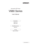
Hand-held Reader Writer
User's Manual
Hand-held Reader Writer
V680-CHUD
V680-CH1D
V680-CH1D-PSI
ID Tags
V680/V680S Series
Man. No.: Z272-E1-06
Introduction
Thank you for purchasing a V680/V680S-series RFID System. This manual describes the functions,
performance, and application methods needed for optimum use of the V680/V680S-series RFID System.
Please observe the following items when using the V680-series RFID System.
• Allow the V680/V680S-series RFID System to be installed and operated only by qualified specialist with a
sufficient knowledge of electrical systems.
• Read and understand this manual before attempting to use the V680/V680S-series RFID System and use
the V680/V680S-series RFID System correctly.
• Keep this manual in a safe and accessible location so that it is available for reference when required.
READ AND UNDERSTAND THIS DOCUMENT
Section 1 Product Overview
Introduction Section
ÇÕǹÇflÇ
ëÊ 1 èÕ1
Introduction
Section 2 Communications Preparations
Section
ëÊ 2 èÕ2
Section 3 Commands
Section
ëÊ 3 èÕ3
Section
ëÊ 4 èÕ4
Section 4 Functions
Section 5 Troubleshooting
Section 5
Section 6 Appendices
Section 6
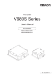
RFID System
V680-CHUD
V680-CH1D
V680-CH1D-PSI
V680 Series
V680S Series
User’s Manual
Hand-held Reader/Writer
Hand-held Reader/Writer
Hand-held Reader/Writer
RF Tags
RF Tags
Introduction
Introduction
READ AND UNDERSTAND THIS DOCUMENT
Please read and understand this document before using the products. Please consult your OMRON representative if you have any questions or comments.
WARRANTY
OMRON’s exclusive warranty is that the products are free from defects in materials and workmanship for a period of one year (or other period if specified)
from date of sale by OMRON.
OMRON MAKES NO WARRANTY OR REPRESENTATION, EXPRESS OR IMPLIED, REGARDING NON-INFRINGEMENT, MERCHANTABILITY, OR FITNESS FOR PARTICULAR PURPOSE OF THE PRODUCTS. ANY BUYER OR USER ACKNOWLEDGES THAT THE BUYER OR USER ALONE HAS
DETERMINED THAT THE PRODUCTS WILL SUITABLY MEET THE REQUIREMENTS OF THEIR INTENDED USE. OMRON DISCLAIMS ALL OTHER
WARRANTIES, EXPRESS OR IMPLIED.
LIMITATIONS OF LIABILITY
OMRON SHALL NOT BE RESPONSIBLE FOR SPECIAL, INDIRECT, OR CONSEQUENTIAL DAMAGES, LOSS OF PROFITS OR COMMERCIAL LOSS IN
ANY WAY CONNECTED WITH THE PRODUCTS, WHETHER SUCH CLAIM IS BASED ON CONTRACT, WARRANTY, NEGLIGENCE, OR STRICT LIABILITY.
In no event shall responsibility of OMRON for any act exceed the individual price of the product on which liability is asserted.
IN NO EVENT SHALL OMRON BE RESPONSIBLE FOR WARRANTY, REPAIR, OR OTHER CLAIMS REGARDING THE PRODUCTS UNLESS OMRON’S
ANALYSIS CONFIRMS THAT THE PRODUCTS WERE PROPERLY HANDLED, STORED, INSTALLED, AND MAINTAINED AND NOT SUBJECT TO CONTAMINATION, ABUSE, MISUSE, OR INAPPROPRIATE MODIFICATION OR REPAIR.
SUITABILITY FOR USE
THE PRODUCTS CONTAINED IN THIS DOCUMENT ARE NOT SAFETY RATED. THEY ARE NOT DESIGNED OR RATED FOR ENSURING SAFETY OF
PERSONS, AND SHOULD NOT BE RELIED UPON AS A SAFETY COMPONENT OR PROTECTIVE DEVICE FOR SUCH PURPOSES. Please refer to separate catalogs for OMRON's safety rated products.
OMRON shall not be responsible for conformity with any standards, codes, or regulations that apply to the combination of products in the customer’s application or use of the product.
At the customer’s request, OMRON will provide applicable third party certification documents identifying ratings and limitations of use that apply to the products. This information by itself is not sufficient for a complete determination of the suitability of the products in combination with the end product, machine,
system, or other application or use.
The following are some examples of applications for which particular attention must be given. This is not intended to be an exhaustive list of all possible uses
of the products, nor is it intended to imply that the uses listed may be suitable for the products:
• Outdoor use, uses involving potential chemical contamination or electrical interference, or conditions or uses not described in this document.
• Nuclear energy control systems, combustion systems, railroad systems, aviation systems, medical equipment, amusement machines, vehicles, safety
equipment, and installations subject to separate industry or government regulations.
• Systems, machines, and equipment that could present a risk to life or property.
Please know and observe all prohibitions of use applicable to the products.
NEVER USE THE PRODUCTS FOR AN APPLICATION INVOLVING SERIOUS RISK TO LIFE OR PROPERTY WITHOUT ENSURING THAT THE SYSTEM
AS A WHOLE HAS BEEN DESIGNED TO ADDRESS THE RISKS, AND THAT THE OMRON PRODUCT IS PROPERLY RATED AND INSTALLED FOR THE
INTENDED USE WITHIN THE OVERALL EQUIPMENT OR SYSTEM.
PERFORMANCE DATA
Performance data given in this document is provided as a guide for the user in determining suitability and does not constitute a warranty. It may represent the
result of OMRON’s test conditions, and the users must correlate it to actual application requirements. Actual performance is subject to the OMRON Warranty
and Limitations of Liability.
CHANGE IN SPECIFICATIONS
Product specifications and accessories may be changed at any time based on improvements and other reasons.
It is our practice to change model numbers when published ratings or features are changed, or when significant construction changes are made. However,
some specifications of the product may be changed without any notice. When in doubt, special model numbers may be assigned to fix or establish key specifications for your application on your request. Please consult with your OMRON representative at any time to confirm actual specifications of purchased products.
DIMENSIONS AND WEIGHTS
Dimensions and weights are nominal and are not to be used for manufacturing purposes, even when tolerances are shown.
ERRORS AND OMISSIONS
The information in this document has been carefully checked and is believed to be accurate; however, no responsibility is assumed for clerical, typographical,
or proofreading errors, or omissions.
PROGRAMMABLE PRODUCTS
OMRON shall not be responsible for the user’s programming of a programmable product, or any consequence thereof.
COPYRIGHT AND COPY PERMISSION
This document shall not be copied for sales or promotions without permission. This document is protected by copyright and is intended solely for use in conjunction with the product. Please notify us before copying or reproducing this document in any manner, for any other purpose. If copying or transmitting this
document to another, please copy or transmit it in its entirety.
2
RFID System
User's Manual
Introduction
Introduction
Safety Precautions
Signal Words Used in This Manual
The following symbols are used in this manual to indicate precautions that must be observed to ensure safe
use of the V680/V680S-series RFID System. The precautions provided here contain important safety
information. Be sure to observe these precautions.
The following signal words are used in this manual.
WARNING
Indicates a potentially hazardous situation which, if not avoided, will result in minor or
moderate injury, or may result in serious injury or death. Additionally, there may be significant property damage.
Meanings of Alert Symbols
Indicates the possibility of explosion under specific conditions.
Indicates general prohibitions for which there is no specific symbol.
Warning
WARNING
This Product is not designed or rated for ensuring safety of persons. Do not use it for such
purposes.
RFID System
User's Manual
3
Introduction
Introduction
Precautions for Safe Use
Observe the following precautions to ensure safe use of the Product.
1. Do not use the Product in environments with flammable, explosive, or corrosive gasses.
2. Do not attempt to disassemble, repair, or modify the Product.
3. The USB driver must be installed in the personal computer before connecting the V680-CHUD to a
personal computer.
4. Do not subject cables to excessive loads.
5. Observe all warnings and precautions given in the body of this manual.
6. Discontinue usage and turn OFF the power supply immediately if you notice any unusual odors, if the
Product is abnormally hot, or if the Product starts smoking.
7. Dispose of the Product as industrial waste.
4
RFID System
User's Manual
Introduction
Always observe the following precautions to prevent operation failures, malfunctions, and adverse effects on
Introduction
Precautions for Correct Use
performance and equipment.
1. Installation and Storage Environment
Do not use or store the Product in the following locations.
• Locations exposed to corrosive gases, dust, metallic powder, or salts
• Locations not within the specified operating temperature range
• Locations subject to rapid changes in temperature or condensation
• Locations not within the specified operating humidity range
• Locations subject to direct vibration or shock outside the specified ranges
• Locations subject to spray of water, oil, or chemicals
2. Environment
• This Product uses a frequency band of 13.56 MHz to communicate with RF Tags. Some motors,
inverters, switching power supplies, and other devices generate electrical noise that will affect communications with the RF Tags. If any of these devices are located in the vicinity of the Product, they
may affect communications with RF Tags, and may possibly damage the RF Tags. Prior to using the
Product in the vicinity of any of these devices, perform a test to determine whether the Product can
be used under the resulting influence.
• Observe the following precautions to minimize the effects of normal noise.
(1) Ground all metal objects in the vicinity of the Product to 100 or less.
(2) Do not use the Product near high-voltage or high-current lines.
• Connectors are not waterproof. Do not use the Product where mists are present.
• Do not use chemicals that would affect the materials used in the product.
• Be sure the USB connector is properly inserted when using the USB port on the V680-CHUD.
• Always use the specified AC Adaptor (V600-A22) when using the V680-CH1D.
• The communications range is adversely affected if there is any metal material around the RF Tag.
•Transmission will not be possible if the front and back panels are mistakenly reversed and the Unit is
mounted to a metallic surface.
V680-D1KP66MT
V680-D8KF67M
V680S-D2KF67M
V680S-D2KF68M
V680S-D8KF67M
V680S-D8KF68M
•The communications range will be reduced when the Unit is not mounted to a metallic surface.
mounted to a metallic surface.
V680-D1KP66MT
V680-D8KF67M
V680S-D2KF67M
V680S-D2KF68M
V680S-D8KF67M
V680S-D8KF68M
•The maximum communications range can be obtained when the Antenna faces the RF tag directly.
When the RF tag is installed at a tilt, the communications range is reduced. Consider the effect of
the RF tag at tilt when installing the RF Tag.
•Provide the mounting distances between plural RF tags to prevent them from malfunctions due to
mutual interference
RFID System
User's Manual
5
Introduction
Introduction
•If the central axis of an antenna and RF tag shifts, a communications range will fall.
•Do not touch the product immediately after usage at high temperatures. Doing so may occasionally
result in burning.
3. Host Communications
Always confirm that the Product has been started before attempting to communicate with it from the
host. Also, when the Product is started, unstable signals may be output from the host interface. When
starting operation, clear the reception buffers in the host or take other suitable countermeasures.
4. Cleaning
• Do not clean the product with thinners, benzene, or other organic solvents. These will dissolve the
resin parts and coating on the case.
6
RFID System
User's Manual
Introduction
Introduction
How to Read this Manual
Meanings of Symbols
Indicates particularly important points related to a function, including precautions and application advice.
Indicates page numbers containing relevant information.
Indicates reference to helpful information and explanations for difficult terminology.
RFID System
User's Manual
7
Introduction
Introduction
8
MEMO
RFID System
User's Manual
Introduction
Introduction
Table of Contents
Introduction
Safety Precautions
3
Precautions for Safe Use
4
Precautions for Correct Use
5
How to Read this Manual
7
Section 1 Product Overview
11
Features
12
Using Heat-resistive Tags (V680-D1KP58HTN and V680-D1KP58HT)
14
Names and Functions of Components
19
System Configuration
22
Operation Flowchart
25
Section 2 Communications Preparations
29
V680-CHUD Communications Preparations
30
V680-CH1D Communications Preparations
44
V680-CH1D-PSI Communications Preparations
47
Setting the Hand-held Reader/Writer
48
Communications Test
52
Section 3 Commands
55
Communicating with RF Tags
56
V600 and V680 Command Comparison
57
V680 Commands
59
V600 Commands
83
Section 4 Functions
119
Hand-held Reader/Writer Functions
120
Write Protection Function
121
RF Tag Service Life Detection
123
Memory Check Function in RF Tag
125
RF Tag Memory Error Correction
126
RFID System
User's Manual
9
Introduction
Introduction
Section 5 Troubleshooting
127
Error Tables
128
Troubleshooting Flowchart
129
Section 6 Appendices
Specifications and Dimensions
132
RF Tag Memory Map
149
RF Tag Memory Capacities and Memory Types (V680 Series)
150
List of ASCII Characters
151
Degree of Protection
152
Revision History
10
131
RFID System
User's Manual
154
Section 1
Section 1
Product Overview
12
Using Heat-resistive Tags
(V680-D1KP58HTN and V680-D1KP58HT)
14
Names and Functions of Components
19
System Configuration
22
Operation Flowchart
25
RFID System
User's Manual
Product Overview
Features
11
Section 1
Product Overview
Features
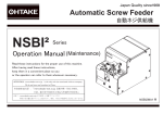
The V680-series Hand-held Reader/Writer incorporates a V680-series Antenna and Controller into a compact
Section 1
design. Data can be read from or written to the RF Tag simply by approaching or touching the RF Tag with the
Hand-held Reader/Writer.
Features
Personal computer
Hand-held Terminal
manufactured by Zebra Technologies Inc.
Hand-held Terminal Recommended
for the V680-CH1D-PSI: Work About Pro
Hand-held Reader/Writers
RF Tags
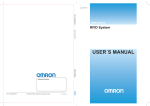
■ V680-CHUD
This Hand-held Reader/Writer provides a USB connector that conforms to the USB 1.1 standard. Connecting the Hand-held Reader/Writer to a personal computer or Hand-held Terminal gives it superior
portability, and operability.
■ V680-CH1D
A built-in RS-232C interface allows this Hand-held Reader/Writer to be connected to a personal computer or programmable controller.
■ V680-CH1D-PSI
A built-in RS-232C interface allows this Hand-held Reader/Writer to be connected to a Hand-held Terminal, giving it superior portability, and operability.
12
RFID System
User's Manual
Section 1
Product Overview
■ Differences between Version 1.0 and 1.1
The following functions have been added to version 1.1 in comparison to version 1.0. Functions are
upwardly compatible, so version 1.0 can be replaced with version 1.1.
Setting the Tag memory setting to CA1D Mode enables reading and writing Heat-resistant Tags that
Section 1
CA1D Mode Setting Added for Tag Memory
Features
were written by the V680-CA1D/-CA2D.
Parameter Added to PARAMETER SET (SP) Command
A parameter to set the Tag memory setting was added to the PARAMETER SET (SP) command.
The Tag memory setting is made in the Hand-held Reader/Writer. A different memory map may be used when reading
or writing Heat-resistant Tags that were written by the V680-CA1D/-CA2D from a Reader/Writer that is manufactured by
a company other than OMRON. Refer to Operation When Tag Memory Setting Is Set to Standard Mode in this section.
p.17
■ Checking the Version
Version 1.0
Version 1.1
Nothing
Present
RFID System
User's Manual
13
Section 1
Product Overview
Using Heat-resistive Tags (V680-D1KP58HTN and
V680-D1KP58HT)
Section 1
This section provides information for using Heat-resistive Tags (V680-D1KP58HTN or V680-D1KP58HT).
If you are not using a Heat-resistive Tag, set the Tag memory setting to Standard Mode.
Using Heat-resistive Tags (V680-D1KP58HTN and V680-D1KP58HT)
Precautions for Saving Data at High Temperatures
If you are using a Heat-resistive Tag, write the data again after saving the data at a high temperature
even if it is not necessary to change the data. A "high temperature" is one between 110C and 200C.
Using the V680-CA1D/-CA2D
If you are using Heat-resistive Tags (V680-D1KP58HTN or V680-D1KP58HT) and also using the
V680-CA1D/-CA2D, set the Tag memory setting of the V680-CH@D (version 1.1 or newer) to CA1D
Mode.
If you are not using the V680-CA1D/-CA2D, the Tag memory setting does not need to be changed.
Refer to information in Names and Functions of Components.
■ Combining the V680-CA1D/-CA2D with Other Models
When using other models of Controller with the V680-CA1D/-CA2D, make sure that the version allows
setting the Tag memory setting to CA1D Mode.
To use the V680-CA5D01-V2/-CA5D02-V2, it must be version 2.3 or newer.
To use the V680-CH@D, it must be version 1.1 or newer.
To use the CS/CJ1W-V680C1@, it must be version 1.2 or newer.
Refer to Checking the Version for information on product versions.
p.13
14
RFID System
User's Manual
Section 1
Product Overview
■ Introduction
The address maps in the RF Tags for the V680-D1KP@@ (except for the V680-D1KP58HT) are
reversed between the V680-CA1D/-CA2D ID Controllers and V680-CH@D Hand-held Reader/Writer
1.0) and V680-CH@D (with Tag memory setting set to Standard Mode for version 1.1 or newer) Handheld Reader/Writers. Therefore, when you use RF Tags with a V680-CA1D/-CA2D ID Controller,
Reader/Writers that are used for the same RF Tags.
Reading/writing
OK
V680-CH@D
(Version 1.1 or newer:
Tag memory setting set to
CA1D Mode.)
V680-CA1D/-CA2D
Address maps
reversed.
Using Heat-resistive Tags (V680-D1KP58HTN and V680-D1KP58HT)
always set the Tag memory setting to CA1D Mode in any other models of ID Controller or Hand-held
Section 1
(with Tag memory setting set to CA1D Mode for version 1.1 or newer), and the V680-CH@D (version
Reading/writing
OK
Standard model:
V680-CH@D (Ver.1.0)
V680-CH@D
(Version 1.1 or newer:
Tag memory setting set
to Standard Mode.)
RFID System
User's Manual
15
Section 1
Product Overview
■ Applicable RF Tags
Only the V680-D1KP@@ RF Tags can be used when the Tag memory setting is set to CA1D Mode.
V680-D@KF@@ RF Tags cannot be used.
Section 1
RF Tags That Can Be Used
RF Tags That Cannot Be Used
Using Heat-resistive Tags (V680-D1KP58HTN and V680-D1KP58HT)
Models
Models
V680-D1KP58HT
V680-D2KF52M
V680-D1KP58HTN
V680-D8KF67
V680-D1KP52MT
V680-D8KF67M
V680-D1KP53M
V680-D8KF68
V680-D1KP66T
V680-D32KF68
V680-D1KP66MT
V680S-D2KF67
V680S-D2KF67M
V680S-D2KF68
V680S-D2KF68M
V680S-D8KF67
V680S-D8KF67M
V680S-D8KF68
V680S-D8KF68M
■ CA1D Mode Setting for Tag Memory and Write Protection
When setting the Tag memory setting to CA1D Mode, always disable write protection.
■ Setting the Tag Memory Setting to CA1D Mode
When changing an existing system to use the V680-CA1D/-CA2D, there are restrictions in the command system and write protection function.
The following settings are required if the Tag memory setting is set to CA1D Mode.
1.Process code J in PARAMETER SET (SP) command: Set the command system setting to 0 to set
the command system to V600 commands.
2.Process code H in PARAMETER SET (SP) command: Set the write protection function setting to 1 to
disable write protection.
3.Process code L in PARAMETER SET (SP) command: Set the Tag memory setting to 1 to set CA1D
Mode.
Standard Mode is the default Tag memory setting.
For details on the PARAMETER SET (SP) command, refer to PARAMETER SET (SP) under V680 Commands or V600
Commands in Section 3 Commands.
p.78, p.116
16
RFID System
User's Manual
Section 1
Product Overview
■ Operation When Tag Memory Setting Is Set to Standard Mode
When data that was written to a V680-D1KP58HTN RF Tag with the V680-CA1D/-CA2D ID Controller
is read from a V680-CH@D Hand-held Reader/Writer, the data from addresses that are reversed in
If you are going to use a V680-CH@D Reader/Writer in the same line as a V680-CA1D/-CA2D ID Controller, use a V680-CH@D Reader/Writer with version 1.1 or newer and set the Tag memory setting to
Address
0000 hex
0001 hex
0002 hex
0003 hex
0004 hex
0005 hex
0006 hex
0007 hex
:
:
03E0 hex
03E1 hex
03E2 hex
03E3 hex
03E4 hex
03E5 hex
03E6 hex
03E7 hex
Data written with
V680-CA1D/-CA2D
Using Heat-resistive Tags (V680-D1KP58HTN and V680-D1KP58HT)
CA1D Mode.
Data read with V680-CH@D (version
1.0) or V680-CH@D (version 1.1 or
newer with Tag memory setting set to
Standard Mode)
01 hex
23 hex
45 hex
67 hex
89 hex
AB hex
CD hex
EF hex
:
:
00 hex
00 hex
00 hex
00 hex
00 hex
Addresses are
00 hex
00 hex reversed by block.
00 hex
Section 1
one-block (eight-byte) units is read.
00 hex
00 hex
00 hex
00 hex
00 hex
00 hex
00 hex
00 hex
:
:
01 hex
23 hex
45 hex
67 hex
89 hex
AB hex
CD hex
EF hex
RFID System
User's Manual
17
Section 1
Product Overview
■ Operation When Tag Memory Setting Is Set to CA1D Mode
If the Tag memory setting for the V680-CH@D (version 1.1 or newer) is set to CA1D Mode, data is read
from or written to addresses that are reversed in block units for the V680-D1KP@@ (except for the
Section 1
V680-D1KP58HT) in the same way as for the V680-CA1D/-CA2D. Therefore, data can be read from
the same addresses as those to which data was written by the V680-CA1D/-CA2D.
Using Heat-resistive Tags (V680-D1KP58HTN and V680-D1KP58HT)
Data written with
V680-CA1D/-CA2D
Address
0000 hex
0001 hex
0002 hex
0003 hex
0004 hex
0005 hex
0006 hex
0007 hex
:
:
03E0 hex
03E1 hex
03E2 hex
03E3 hex
03E4 hex
03E5 hex
03E6 hex
03E7 hex
Data read with V680-CH?D (version
1.1 or newer with Tag memory setting
set to CA1D Mode)
01 hex
01 hex
23 hex
23 hex
45 hex
45 hex
67 hex
67 hex
89 hex
89 hex
AB hex
AB hex
CD hex
CD hex
EF hex
EF hex
: Same as data read with :
:
:
V680-CA1D/-CA2D.
00 hex
00 hex
00 hex
00 hex
00 hex
00 hex
00 hex
00 hex
00 hex
00 hex
00 hex
00 hex
00 hex
00 hex
00 hex
00 hex
■ Canceling CA1D Mode
To cancel CA1D Mode, use the PARAMETER SET (SP) command to set the Tag memory setting to
Standard Mode.
Process code L: Set the Tag memory setting to Standard Mode. For the V600 protocol, set the tag
memory setting to 0. For the V680 protocol, set the tag memory setting to 00.
For details on the PARAMETER SET (SP) command, refer to PARAMETER SET (SP) under V680 Commands or V600
Commands in Section 3 Commands.
p.78, p.116
When CA1D Mode is canceled, the address mapping with the RF Tags will be different from the ones written in CA1D
Mode. This may cause unexpected addresses to be read or written. When canceling CA1D Mode, initialize the data in
the RF Tags before using them.
18
RFID System
User's Manual
Section 1
Product Overview
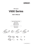
Names and Functions of Components
V680-CHUD
Section 1
Antenna
■ Operation Indicator (LED)
Display
Meaning
A command has been received from the host device.
Communications with the RF Tag have completed normally.
Activate switch
Lit green
When the power is turned ON, after initialization of the Hand-held
Reader/Writer is completed.
Communications with the RF Tag are in progress.
Flashing green
A communications error with the RF Tag has occurred.
A CPU error has occurred.
Lit red
An RF Tag non-existent error has occurred.
Names and Functions of Components
Operation indicator (LED)
A communications error with the host device has occurred.
Flashing red
Interface connector
After the operation indicator is lit or flashing for a certain time, it will turn OFF.
■ Activate Switch
When button commands or commands with button communications specifications (button trigger or button auto) are used and the activate switch is
pressed, communications with the RF Tag will start. (For details on button
communications specifications, refer to Section 3 Commands.)
■ Interface Connector
This is a USB interface with an A-series plug based on USB 1.1.
■ Antenna
To communicate with the RF Tag, move the antenna close to it.
V680-CH1D
RFID System
User's Manual
19
Section 1
Product Overview
Antenna
■ Operation Indicator (LED)
Display
Meaning
Section 1
A command has been received from the host device.
Operation indicator (LED)
Communications with the RF Tag have completed normally.
Lit green
Names and Functions of Components
When the power is turned ON, after initialization of the Hand-held
Reader/Writer is completed
When the power is turned ON and the reset button is pressed for
two seconds or more (initialization stand-by mode).
Activate switch
Reset button
Flashing green
Communications with the RF Tag are in progress.
A communications error with the RF Tag has occurred.
AC Adaptor
connection jack
A CPU error has occurred.
Lit red
An RF Tag non-existent error has occurred.
A communications error with the host device has occurred.
Flashing red
After the operation indicator is lit or flashing for a certain time, it will turn OFF.
Serial interface
connector
■ Activate Switch
When button commands or commands with button communications specifications (button trigger or button auto) are used and the activate switch is
pressed, communications with the RF Tag will start. (For details on button
communications specifications, refer to Section 3 Commands.)
If the activate switch is pressed with the Hand-held Reader/Writer in the initialization stand-by mode (with the green indicator flashing), the function
settings will be initialized.
■ Reset Button
Press this button for two seconds or more when the power is first turned
ON to put the Hand-held Reader/Writer into the initialization stand-by
mode.
■ AC Adaptor Connection Jack
This is a connection jack for the V600-A22 AC Adaptor.
■ Serial Interface Connector
This is a serial interface with an RS-232C-compliant D-Sub 9-pin connector.
■ Antenna
To communicate with the RF Tag, move the antenna closer to it.
V680-CH1D-PSI
20
RFID System
User's Manual
Section 1
Product Overview
Antenna
■ Operation Indicator (LED)
Display
Meaning
Communications with the RF Tag have completed normally.
When the power is turned ON, after initialization of the Hand-held
Reader/Writer is completed.
When the power is turned ON and the reset button is pressed for
two seconds or more (initialization stand-by mode).
Activate switch
Reset button
Flashing green
Communications with the RF Tag are in progress.
A communications error with the RF Tag has occurred.
A CPU error has occurred.
Lit red
An RF Tag non-existent error has occurred.
A communications error with the host device has occurred.
Flashing red
Names and Functions of Components
Lit green
Section 1
A command has been received from the host device.
Operation indicator (LED)
After the operation indicator is lit or flashing for a certain time, it will turn OFF.
Serial interface
connector
■ Activate Switch
When button commands or commands with button communications specifications (button trigger or button auto) are used and the activate switch is
pressed, communications with the RF Tag will start. (For details on button
communications specifications, refer to Section 3 Commands.)
If the activate switch is pressed with the Hand-held Reader/Writer in the initialization stand-by mode (with the green indicator flashing), the function
settings will be initialized.
■ Reset Button
Press this button for two seconds or more when the power is first turned ON
to put the Hand-held Reader/Writer into the initialization stand-by mode.
■ Serial Interface Connector
This is a serial interface with an RS-232C-compliant D-Sub 9-pin connector.
■ Antenna
To communicate with the RF Tag, move the antenna closer to it.
RFID System
User's Manual
21
Section 1
Product Overview
System Configuration
V680-CHUD
Section 1
The V680-CHUD Hand-held Reader/Writer can communicate with host devices that have a USB interface,
such as personal computers.
Host Devices
System Configuration
Personal computer
Hand-held Reader/Writer
RF Tags
The V680-CHUD Hand-held Reader/Writer can be used with any RF Tag in the V680/V680S Series.
For details on Hand-held Reader/Writer and RF Tag models, refer to Section 6 Appendices.
p.132, p.150
When using a V680-D8KF@@, to use the V680-CHUD of production after October 2014.
22
RFID System
User's Manual
Section 1
Product Overview
V680-CH1D
A built-in RS-232C serial interface in the V680-CH1D Hand-held Reader/Writer allows communication with
personal computers and programmable controllers that are equipped with an RS-232C interface.
Section 1
Host Devices
System Configuration
Programmable controller
(Some models require a conversion connector.)
Personal computer
Hand-held Reader/Writer
V680-CH1D
V600-A22 (option)
RF Tags
The V680-CH1D Hand-held Reader/Writer can be used with any RF Tag in the V680/V680S Series.
For details on Hand-held Reader/Writer and RF Tag models, refer to Section 6 Appendices.
p.132, p.150
When using a V680-D8KF@@, to use the V680-CH1D of production after October 2014.
RFID System
User's Manual
23
Section 1
Product Overview
V680-CH1D-PSI
A built-in RS-232C serial interface in the V680-CH1D-PSI Hand-held Reader/Writer allows communications
with personal computers and programmable controllers that are equipped with an RS-232C interface
Section 1
Host Devices
System Configuration
Recommended Hand-held Terminal:
Work About Pro manufactured by Zebra Technologies Inc.
Hand-held Reader/Writer
V680-CH1D-PSI
RF Tags
The V680-CH1D-PSI Hand-held Reader/Writer can be used with any RF Tag in the V680/V680S Series.
For details on Hand-held Reader/Writer and RF Tag models, refer to Section 6 Appendices.
p.132, p.150
When using a V680-D8KF@@, to use the V680-CH1D-PSI of production after October 2014.
24
RFID System
User's Manual
Section 1
Product Overview
Operation Flowchart
V680-CHUD
Operation Flowchart
Preparation
Section 1
Connect the V680-CHUD to the host device.
When connecting for the first time, the USB driver must be installed.
p.31 to p.34
Test
Perform the communications test between the host device and
Hand-held Reader/Writer.
p.53
Perform the communications test between the RF Tag and
Hand-held Reader/Writer.
p.53
Check the ambient environment.
Transmission
p.132
Operate the system using real commands.
p.55
RFID System
User's Manual
25
Section 1
Product Overview
Operation Flowchart
Communications preparation
Section 1
Preparation
V680-CH1D
Connect the V680-CH1D to the host device.
p.45
Set the communications parameters between the host device and
Hand-held Reader/Writer.
p.48
Test
Perform the communications test between the host device and
Hand-held Reader/Writer.
p.53
Perform the communications test between the RF Tag and
Hand-held Reader/Writer.
p.53
Check the ambient environment.
Transmission
p.132
26
RFID System
User's Manual
Operate the system using real commands.
p.55
Section 1
Product Overview
Connect the V680-CH1D-PSI to the host device.
p.47
Operation Flowchart
Communications preparation
Section 1
Preparation
V680-CH1D-PSI
Set the communications parameters between the host device and
Hand-held Reader/Writer.
p.48
Test
Perform the communications test between the host device and
Hand-held Reader/Writer.
p.53
Perform the communications test between the RF Tag and
Hand-held Reader/Writer.
p.53
Check the ambient environment.
Transmission
p.132
Operate the system using real commands.
p.55
RFID System
User's Manual
27
Section 1
Product Overview
MEMO
Section 1
Operation Flowchart
28
RFID System
User's Manual
Section 2
Communications Preparations
Section 2
30
V680-CH1D Communications Preparations
44
V680-CH1D-PSI Communications Preparations
47
Setting the Hand-held Reader/Writer
48
Communications Test
52
RFID System
User's Manual
Communications Preparations
V680-CHUD Communications Preparations
29
Section 2
Communications Preparations
V680-CHUD Communications Preparations
Connections
■ Connecting the Cable
Section 2
1. Connect the cable connector to the USB connector on the host
device, making sure that the connector is oriented correctly
V680-CHUD Communications Preparations
and not inserted at an angle.
■ Removing the Cable
1. Remove the cable.
Close the software application at the host device and then pull out the connector in a straight line, not at an angle.
If the connector is removed while the software is running at the host
device, operation may stop due to a software malfunction error.
Restart the software if operation becomes impossible.
30
RFID System
User's Manual
Section 2
Communications Preparations
Installing the USB Driver (V680-CHUD)
When connecting the Hand-held Reader/Writer to the host device for the first time, the USB driver must
be installed at the host device.
■ Downloading the USB Driver
Download the USB Driver for the V680-CHUD from the web site.
Section 2
For details, ask your OMRON sales representative.
■ Installing the USB Driver
host personal computer using the following procedure.
Operation on other operating systems is not supported.
Windows XP
1. Turn ON the power to the personal computer and start Windows XP.
2. Connect the Hand-held Reader/Writer to the personal computer.
For details on connection methods, refer to Connections.
p.30
V680-CHUD Communications Preparations
The V680-CHUD supports the Windows XP or Windows 7 operating system. Install the driver in the
Wait for the following window to be displayed.
3. When the following dialog box is displayed, select the Install from a list or specific location (Advanced)
Option and click the Next Button.
RFID System
User's Manual
31
Section 2
Communications Preparations
4. Click the Browse Button when the Found New Hardware Wizard Dialog Box appears, select the folder
in which the downloaded file V680-CHUD_100.inf was saved, and click the Next button.
Section 2
V680-CHUD Communications Preparations
5. Click the Continue Anyway Button.
32
RFID System
User's Manual
Section 2
Communications Preparations
6. The USB Driver installation will begin.
Section 2
V680-CHUD Communications Preparations
7. When the following window is displayed, installation has been completed.
8. Click the Finish Button.
RFID System
User's Manual
33
Section 2
Communications Preparations
Checking Installation
Check that the driver is correctly installed.
1. Connect the Hand-held Reader/Writer to the personal computer.
Section 2
2. On the Start Menu, select Control Panel - System.
V680-CHUD Communications Preparations
3. Click the Device Manager Button in the Hardware Tab Page.
4. Select Ports (COM & LPT), and check that OMRON RFID USB COM is displayed.
The driver is correctly installed if this port is displayed.
Communications with the Hand-held Reader/Writer can be performed with the COM number displayed in parentheses after
OMRON RFID USB COM.
34
RFID System
User's Manual
Section 2
Communications Preparations
Windows Vista
1. Turn ON the power to the personal computer and start Windows Vista.
2. Connect the Hand-held Reader/Writer to the computer via USB.
For details on connection methods, refer to Connections.
Section 2
p.30
3. When the following window is displayed, select Locate and install driver software (recommended)
Button.
V680-CHUD Communications Preparations
Wait for the following window to be displayed.
4. If the User Account Control Dialog Box is displayed, click the Continue Button.
5. If a dialog box appears for searching for software online, select the Don't search online Option. If this
dialog box is not displayed, go to the next step.
6. When the following window is displayed, select I don’t have the disc. Show me other options. Button.
RFID System
User's Manual
35
Section 2
Communications Preparations
7. When
the following window is displayed, select Browse my computer for driver software
(advanced) Button.
Section 2
V680-CHUD Communications Preparations
8. Click the Browse Button, and select the folder in which the downloaded file V680_CHUD_200.inf is
saved. Then click the Next Button.
9. When the following window is displayed, select Install this driver software anyway Button.
36
RFID System
User's Manual
Section 2
Communications Preparations
When the following window is displayed, installation is completed.
Section 2
V680-CHUD Communications Preparations
10. Click the Close Button.
The displays that actually appear depend on your computer environment.
RFID System
User's Manual
37
Section 2
Communications Preparations
Checking Installation
Check that the driver is correctly installed.
1. Connect the Hand-held Reader/Writer to the personal computer.
2. On the Start Menu, select Control Panel - Performance and Maintenance.
Section 2
3. Click the System Icon.
V680-CHUD Communications Preparations
4. Click the Device Manager Button on the Hardware Tab Page.
5. Select Ports (COM & LPT), and check that OMRON RFID USB COM is displayed.
The driver is correctly installed if this port is displayed.
Communications with the Hand-held Reader/Writer can be performed with the COM number displayed
in parentheses after OMRON RFID USB COM.
38
RFID System
User's Manual
Section 2
Communications Preparations
Windows 7
1. Turn ON the power to the personal computer and start Windows 7.
2. Connect the ID Controller to the computer via USB.
Section 2
Refer to Connections for information on the connection method.
p.30
V680-CHUD Communications Preparations
3. Select Settings - Control Panel - System and Security from the Windows Start Menu.
4. Click the Device Manager Button.
RFID System
User's Manual
39
Section 2
Communications Preparations
5. Right-click the Other devices - V680-CHUD and click the Properties.
Section 2
V680-CHUD Communications Preparations
6. Click the Update Driver Button.
7. Once the following dialog box has been displayed, click the Browse my computer for driver software
Button.
40
RFID System
User's Manual
Section 2
Communications Preparations
8. Click the Browse Button and select the folder where the downloaded V680-CHUD_100_win7_@@.inf
is to be saved. Then click the Next Button.
Section 2
V680-CHUD Communications Preparations
9. Click the Install this driver software anyway Button.
The following dialog box will be displayed when the software installation has been completed.
10. Click the Close Button.
RFID System
User's Manual
41
Section 2
Communications Preparations
Checking Installation
Use the following procedure to confirm that the driver has been correctly installed.
1. Turn ON the power to the personal computer and start Windows 7.
Section 2
2. Connect the ID Controller to the computer via USB.
Refer to Connections for information on the connection method.
V680-CHUD Communications Preparations
p.30
3. Select Settings - Control Panel - System and Security from the Windows Start Menu.
4. Click the Device Manager Button.
42
RFID System
User's Manual
Section 2
Communications Preparations
5. Right-click the Other devices - V680-CHUD and click the Properties.
Section 2
V680-CHUD Communications Preparations
6. Select Ports (COM & LPT), and check that OMRON RFID USB COM is displayed.
If the driver is correctly installed, the property window for the V680-CHUD will be displayed as follows:
Communications with the ID Controller can be performed with the COM number displayed in parentheses after OMRON RFID
USB COM.
RFID System
User's Manual
43
Section 2
Communications Preparations
V680-CH1D Communications Preparations
Pin Arrangement of the Host Device Interface Connector
V680-CH1D
Section 2
V680-CH1D Communications Preparations
44
5
1
9
Pin No.
Signal
(See note.)
1
---
2
Receive data
RD
Hand-held Reader/Writer to host
device
3
Send data
SD
Host device to Hand-held Reader/
Writer
6
Connector from Mating Side
Code
(See note.)
Signal direction
---
4
---
---
---
5
Signal ground
SG
-----
6
(Reserved)
---
7
Request send
RS
8
Enable send
CS
9
---
---
Loops inside connector
---
Note: The names of signals at the host device are abbreviated with codes.
Note: For conversion to a 25-pin connector, the SGC-X9P/25P-2 manufactured by Sunhayato, or an
equivalent, is recommended.
RFID System
User's Manual
Section 2
Communications Preparations
■ Connection with the Host Device
Use the following procedure to connect the V680-CH1D to the host device.
1. Connect the V680-CH1D to the RS-232C interface of the host device.
• When connecting to an IBM PC/AT or compatible:
Section 2
To convert from a 9-pin connector to a 25-pin connector, use an SGC-X9P25P-2 conversion connector manufactured by Sunhayato, or an equivalent product.
SGC-X9P25P-2
V680-CH1D Communications Preparations
• When connecting to a PC9801-series computer (D-Sub 25-pin connector):
2. Connect the V600-A22 AC Adaptor to the V680-CH1D.
V600-A22
3. Plug the V600-A22 AC Adaptor into a 100- to 120-VAC power outlet.
Do not use any AC adaptor other than the specified one (V600-A22).
Using any AC adaptor other than the specified one may cause a malfunction, damage, or fire in the V600-CH1D.
Some host devices require a conversion connector.
RFID System
User's Manual
45
Section 2
Communications Preparations
When connecting to a CQM1, CJ1, CS1, etc.
Prepare a connection cable as shown in the connection examples below.
Note: Because both the V680-CH1D interface connector and the interface connector of the CQM1,
CJ1, and CS1 are sockets, a conversion connector is necessary to connect them. Also, the pin
arrangement of the CQM1, CJ1, and CS1 interface connector is different from the RS-232C pin
Section 2
V680-CH1D Communications Preparations
46
arrangement of a personal computer.
V680-CH1D
CQM1/CJ1/CS1
Pin No.
Signal
Pin No.
Signal
1
---
1
---
2
RD
2
SD
3
SD
3
RD
4
---
4
RS
5
SG
5
CS
6
---
6
---
7
RS
7
---
8
CS
8
---
9
---
9
SG
RFID System
User's Manual
Loop
Section 2
Communications Preparations
V680-CH1D-PSI Communications Preparations
Pin Arrangement of the Host Device Interface Connector
V680-CH1D-PSI
1
6
Connector from Mating Side
Signal
(See note.)
Code
(See note.)
1
---
2
Receive data
RD
Hand-held Reader/Writer to host
device
3
Send data
SD
Host device to Hand-held Reader/
Writer
4
---
---
---
5
Signal ground
SG
-----
Signal direction
---
6
Reserved
---
7
Request send
RS
8
Enable send
CS
9
5 VDC
---
Loops inside connector
Host device to Hand-held Reader/
Writer
Note: The names of signals at the host device are abbreviated with codes.
■ Connection with the Host Device
Use the following procedure to connect the V680-CH1D-PSI to the host device.
V680-CH1D-PSI Communications Preparations
9
Pin No.
Section 2
5
1. Connect the V680-CH1D-PSI to the RS-232C interface of the host device.
RFID System
User's Manual
47
Section 2
Communications Preparations
Setting the Hand-held Reader/Writer
Settings
The following settings are used to operate the Hand-held Reader/Writer.
• Serial communications parameters (baud rate, transmission code, parity check, stop bits)
Section 2
• Basic function settings (Auto Command OFF)
Setting the Hand-held Reader/Writer
ABORT command must be used.
These settings can be changed by sending a setting command from the host device. To operate the
Hand-held Reader/Writer with the new setting, the power must be turned OFF then ON again, or the
■ Serial Communications Parameters
The following settings are related to serial communications. Use the COMMUNICATIONS CONDITIONS SETTING (TR) command.
Item
Baud rate (bps)
Contents
2,400, 4,800, 9,600*, 19,200, 38,400
Transmission code
7-unit ASCII 7* or 8-unit JIS 8
Parity check
Even parity*/odd parity/none
Stop bits
2*/1
Note: Items marked by an asterisk (*) are set as the default when shipped from the factory.
■ Basic Function Settings
The Auto Command OFF function can be set. Use the BASIC FUNCTIONS SETTING (FN) command.
Item
Auto Command OFF function
Contents
Yes (1 minute)*, No
Note: Items marked by an asterisk (*) are set as the default when shipped from the factory.
Reading the Settings
Use the SET INFORMATION READ (UL) command to read the settings of the Hand-held Reader/
Writer. The information read by the SET INFORMATION READ command is set in the backup memory
of the Hand-held Reader/Writer. For this reason, care must be taken when the power is first turned ON
after the settings have been changed because the operational settings of the Hand-held Reader/Writer
will be different.
48
RFID System
User's Manual
Section 2
Communications Preparations
Setting the Operating Parameters
To optimize Hand-held Reader/Writer performance and reliability, operating parameters can be set to
match the application. The following parameters can be set: the inter-character monitoring time,
response delay time, auto command cancel time, write protection setting, and protocol.
Usually there will be no problem if the default settings are used, but the system can be optimized by
setting following parameters.
even if the power is turned OFF. When the internal settings are changed with the PARAMETER SET
command (SP), it is not necessary to reset the Hand-held Reader/Writer. The changes will be effective
The PARAMETER SET command is also used to read the parameter settings. For details on the PARAMETER SET
command, refer to PARAMETER SET (SP) in Section 3.
p.78, p.116
■ Inter-character Monitoring Time
The Hand-held Reader/Writer recognizes a command when it receives the end code of a command
string that is sent from the host device. However, if for some reason the command is only partially
received, the Hand-held Reader/Writer will monitor for a fixed period of time after the last character in
the command string is received. If the complete command string is not received after the fixed period of
time has expired, a format error (end code: 14) will be returned.
Setting the Hand-held Reader/Writer
immediately after the PARAMETER SET command is executed.
Section 2
These parameters are stored in the internal memory of the Hand-held Reader/Writer and are saved
No additional data
Host device to Hand-held
Reader/Writer
1
2
3
4
…
End code
Response
Hand-held Reader/Writer
to host device
Error code: 14
External input
Inter-character monitoring time
Setting range
0 to 9,999 (ms)
Note: Default value: 99 (ms)
■ Response Delay Time
The start of returning a response can be changed by setting the response delay time.
The actual time from when sending the command has been completed until returning the response is started is the
Hand-held Reader/Writer's internal processing time (minimum: 0 ms) plus the response delay time (a set value).
Host device to
Hand-held
Reader/Writer
Command
Response
Hand-held
Reader/Writer to host
Internal
processing time
External input
Response delay time
Setting range
0 to 99 (ms)
Note: Default value: 20 (ms)
RFID System
User's Manual
49
Section 2
Communications Preparations
■ Auto Command Cancel Time
The auto command cancel time is used to set the amount of time from after an auto command is sent
until the command processing will be aborted.
After waiting for the tag for a fixed period of time, an "RF Tag non-existent" error (error code: 72) will be
returned to the host device.
Section 2
Host device to
Hand-held
Reader/Writer
Command
Hand-held
Reader/Writer to host
device
External input
Response
Auto command
cancel time
Error code: 72
Setting the Hand-held Reader/Writer
Setting range
0 to 99 (s)
Note: Default value: 60 (s)
■ Write Protection Enable Setting
The write protection enable setting can be used to enable or disable write protection.
00: Write protection function disabled
01: Write protection function enabled default value
For details on write protection settings, refer to Write Protection Function in Section 4.
p.121
■ Protocol Switch
The protocol switch is used to set whether the Hand-held Reader/Writer will use the V680 command
format or the V600 command format.
0: V600 commands (default value)
1: V680 commands
For details, refer to Section 3 Commands.
p.55
■ Tag Memory Setting
The CA1D Mode in the Tag memory setting is used only when using the V680-CA1D/-CA2D.
If you are using the V680-CA1D/-CA2D, set the Tag memory setting to CA1D Mode.
If you are not using the V680-CA1D/-CA2D, set the Tag memory setting to Standard Mode.
0: Standard Mode (default value)
1: CA1D Mode
Refer to Using Heat-resistive Tags (V680-D1KP58HTN and V680-D1KP58HT) in Section 1 Product Overview for information on using Using Heat-resistive Tags (V680-D1KP58HTN or V680-D1KP58HT).
p.14
CA1D Mode can be used with version 1.1 or newer.
Use the VERSION READ (VS) command to read the product version. For details on the VERSION READ (VS) command, refer to VERSION READ (VS) under V680 Commands or V600 Commands in Section 3 Commands.
p.80, p.111
50
RFID System
User's Manual
Section 2
Communications Preparations
Initializing the Settings
A setting command is used to set the Hand-held Reader/Writer but if the communications parameters
are not known or if the setting contents are damaged, it is possible that communications will no longer
be possible with the host device. If this occurs, press both the reset button and the activate switch
when turning ON the power. This will return all settings to the defaults set when the Hand-held Reader/
Writer was shipped from the factory, allowing communications with the host device again.
Section 2
■ Reset Procedure
flashing.
3. With the green operation indicator flashing, remove your finger from the reset button and press the activate switch.
4. When the activate switch is pressed, the operation indicator will stop flashing green. This indicates that
all of the settings have been initialized.
Setting the Hand-held Reader/Writer
1. Turn ON the power while pressing the reset button.
2. Keep the reset button depressed for two seconds or more. The green operation indicator will start
Note: If the activate switch is not pressed within 30 seconds from the time that the operation indicator
starts flashing green, the settings will not be initialized.
The V680-CHUD does not have a reset button. To reset the V680-CHUD, shut down the software on the host device,
and disconnect and reconnect the connector.
RFID System
User's Manual
51
Section 2
Communications Preparations
Communications Test
Test Run Procedure
Section 2
Connect the Hand-held Reader/Writer
to the host device.
Communications Test
Visually check the indicator display.
Execute the online test from the host
Check communications between the host device and Hand-held
device.
Reader/Writer using the test command.
Test run the system.
Finish
52
RFID System
User's Manual
Check operation using real commands.
Section 2
Communications Preparations
Communications Test between Host Device and Hand-held
Reader/Writer
Use the test command to test communications between the Hand-held Reader/Writer and host device.
Before performing communications with the RF Tag, check the Hand-held Reader/Writer connections
and communications.
Section 2
1. Send the test command from the host device.
Communications Test
For detail on the test command, refer to TEST (TS).
p.79, p.110
2. If communications is normal, the Hand-held Reader/Writer will return the received data.
If a response is not returned, refer to Troubleshooting.
p.127
Communications Test between RF Tags and Hand-held Reader/
Writer
Use actual commands to test communications between the RF Tags and the Hand-held Reader/Writer.
1. Send the READ command (RD) with an SA communications specification from the host device.
For details on the READ command, refer to READ (RD).
If using V600 commands, refer to the Auto Read command (AR).
p.65, p.92
The Hand-held Reader/Writer will communicate with the RF Tag and the operation indicator will flash green.
2. Move the antenna of the Hand-held Reader/Writer close to the RF Tag.
The Hand-held Reader/Writer will read the data in the RF Tag when the Hand-held Reader/Writer moves within the interrogation
zone. As a result, the operation indicator will light green and then turn OFF.
RFID System
User's Manual
53
Section 2
Communications Preparations
MEMO
Section 2
Communications Test
54
RFID System
User's Manual
Section 3
Commands
V600 and V680 Command Comparison
57
V680 Commands
59
V600 Commands
83
RFID System
User's Manual
Commands
56
Section 3
Communicating with RF Tags
55
Section 3
Commands
Communicating with RF Tags
Specifying Data Code
Whether the read or write data is treated as an ASCII (or JIS 8) or hexadecimal is specified in each
command.
■ ASCII (JIS 8 Code)
• One character of ASCII or JIS 8 code data occupies 1 byte
• RF Tag
(1 address) of the RF Tag memory.
Address (hex)
Section 3
Communicating with RF Tags
• Examples for Specifying ASCII Text
0010
4
F
“O”
0011
4
D
“M”
0012
5
2
“R”
0013
4
F
“O”
0014
4
E
“N”
1 byte
V600 Commands
W
T
A
1
0
Command code ASCII Processing
setting area number
setting
0
1
0
O
M
R
O
N
CR
Write data
Start address
Terminator
V680 Commands
W
T
S
T
A
1
0
ASCII Processing
Command code Communications setting
area number
specification
0
1
0
O
M
R
O
N
Write data
Start address
CR
Terminator
setting
■ Hexadecimal
• One character is treated as a hexadecimal number. Therefore,
• RF Tag
only numerals 0 through 9 and A to F can be accepted.
Address (hex)
• Two characters of data occupy 1 byte (1 address) of the RF Tag
0010
1
9
memory. Therefore, specify data in 2-character units (in even
0011
9
6
numbers) when using a WRITE command. If an odd number of
1 byte
characters is specified by mistake, an error will occur.
• Examples for Specifying Hexadecimal
V600 Commands
W
T
Command
code
H
1
0
0
1
0
1
Start address
Hexa- Processdecimal ing area
code
number
setting setting
9
9
6
Write data
CR
Terminator
V680 Commands
W
T
Command
code
56
RFID System
User's Manual
S
T
H
1
Hexa- Processdecimal ing area
code
number
setting setting
0
0
1
Start address
0
1
9
9
Write data
6
CR
Terminator
Section 3
Commands
V600 and V680 Command Comparison
The V680-series Hand-held Reader/Writer can use commands in either the V600 command format or the
V680 command format. By using V600 commands, production lines that previously used a V600-series
Reader/Writer can use the same application with the V680-series Hand-held Reader/Writer. New functionality
can be used by using V680 commands.
The PARAMETER SET (SP) command is used to switch between the two command formats. V680 and V600
commands are handled as shown in the following tables.
V680 commands
V600 commands
READ
Command name
Command
code
Data
specification
ST
A/H
READ
RD
A/H
SA
A/H
AUTO READ
AR
A/H
A/H
RD
WRITE
BT
A/H
BUTTON READ
BR
BA
A/H
BUTTON AUTO READ
UR
A/H
ST
A/H
WRITE
WT
A/H
SA
A/H
AUTO WRITE
AW
A/H
BT
A/H
BUTTON WRITE
BW
A/H
BA
A/H
BUTTON AUTO WRITE
UW
A/H
WT
DATA FILL
ST
A/H
DATA FILL
FL
A/H
SA
A/H
AUTO DATA FILL
AF
A/H
C/K
DF
DATA CHECK
MD
ST
C/K
DATA CHECK
MD
OVERWRITE COUNT CONTROL
MD
ST
S/L
OVERWRITE COUNT CONTROL
MD
S
CALCULATION WRITE
---
---
---
CALCULATION WRITE
CW
A/S
ID CODE READ
ID
ST
H
ID CODE READ
ID
H
READ WITH ERROR CORRECTION
QR
ST
A/H
---
---
---
WRITE WITH ERROR CORRECTION
QW
ST
A/H
---
---
---
V600 and V680 Command Comparison
Command Communications
code
specification
Command name
Data
specification
Section 3
Communications Commands
Communications Subcommands
V680 commands
V600 commands
Command
code
Data
specification
COMMAND PROCESSING TERMINATE
AA
---
ABORT (reset)
XZ
---
Command name
Command
code
Data
specification
COMMAND PROCESSING TERMINATE
AA
---
ABORT (reset)
XZ
---
Command name
Controller Control Commands
V680 commands
Command name
V600 commands
Command
code
Command name
Command
code
COMMUNICATIONS CONDITIONS SETTING
TR
COMMUNICATIONS CONDITIONS SETTING
TR
BASIC FUNCTIONS SETTING
FN
BASIC FUNCTIONS SETTING
FN
SET INFORMATION READ
UL
SET INFORMATION READ
UL
PARAMETER SET
SP
PARAMETER SET
SP
RFID System
User's Manual
57
Section 3
Commands
Host Commands
V680 commands
Command name
Command name
Command
code
TEST
TS
TEST
TS
VERSION READ
VS
VERSION READ
VS
Section 3
V600 and V680 Command Comparison
58
V600 commands
Command
code
RFID System
User's Manual
Section 3
Commands
V680 Commands
Communications with the RF Tag
There are four types of communications specifications for communicating with RF Tags using the
Hand-held Reader/Writer.
Single trigger
ST
When the Hand-held Reader/Writer receives a command, it communicates with an RF Tag and then
returns a response.
Single auto
SA
When the Hand-held Reader/Writer receives a command, it waits to detect an RF Tag in the
Antenna's communication area. When the Hand-held Reader/Writer detects an RF Tag, it communicates with the RF Tag and then returns a response.
Button trigger
BT
When the Hand-held Reader/Writer receives a command, it communicates with the RF Tag when
the activate switch is pressed, and then returns a response.
Button auto
BA
When the Hand-held Reader/Writer receives a command, it waits to detect an RF Tag in the
Antenna's communication area after the activate switch is pressed. When the Hand-held Reader/
Writer detects an RF Tag, it communicates with the RF Tag and then returns a response.
Depending on the command, there are limitations on the communications specification that can be used.
For communication specifications that can be used, refer to V600 and V680 Command Comparison in this chapter.
p.57
Single Trigger (ST) Communications Specifications
V680 Commands
Description
Section 3
Communications
specification
Name
After the antenna end of the Hand-held Reader/Writer has been moved close to an RF Tag, a single
trigger (ST) communications specification is sent from the host device to communicate with the RF
Tag.
1. Move the antenna end of the Hand-held Reader/Writer close to the RF Tag.
A
RF Tag
Host device
Hand-held Reader/Writer
C
B
Command
Communications
with RF Tag
D
Response
2. Send the command from the host device to the Hand-held Reader/Writer.
3. The Hand-held Reader/Writer will communicate with the RF Tag.
4. A response will be returned from the Hand-held Reader/Writer to the host device.
If communications end normally, the operation indicator (LED) will light green and then turn OFF.
If an RF Tag is not detected within the Hand-held Reader/Writer's communication area when the command is sent from the host device, an RF Tag Non-existent Error will occur. At this time, the operation
indicator will flash red.
RFID System
User's Manual
59
Section 3
Commands
Single Auto (SA) Communications Specifications
A single auto (SA) communications specification is used to communicate with an RF Tag when the
antenna end of the Hand-held Reader/Writer is moved close to an RF Tag after the command has
been sent from the host device.
Host device
RF Tag
Hand-held Reader/Writer
C
Section 3
V680 Commands
A
Communications
with RF Tag
Command
D
Response
1. Send the command from the host device to the Hand-held Reader/Writer.
2. The Hand-held Reader/Writer will enter the communications stand-by state with the RF Tag, and the
operation indicator (LED) will flash green.
If an RF Tag is not detected within one minute of sending the command, a timeout will occur and an RF Tag Non-existent Error will occur. As a result, the operation indicator will flash red.
3. Communications with the RF Tag will be performed when the antenna end of the Hand-held Reader/
Writer is moved close to the RF Tag.
B
4. A response is returned from the Hand-held Reader/Writer to the host device.
If communications end normally, the operation indicator (LED) will light green and then turn OFF.
60
RFID System
User's Manual
Section 3
Commands
Button Trigger (BT) Communications Specifications
A button trigger (BT) communications specification is used to communicate with an RF Tag when the
antenna is moved close to an RF Tag and the activate switch is pressed after the command has been
sent from the host device.
Host device
RF Tag
Hand-held Reader/Writer
C Press
D
Section 3
E
Response
1. Send the command from the host device to the Hand-held Reader/Writer. The operation indicator will
V680 Commands
Communications
with RF Tag
A
Command
light green.
2. Move the antenna end of the Hand-held Reader/Writer close to the RF Tag.
B
3. Press the Hand-held Reader/Writer activate switch.
4. The Hand-held Reader/Writer will communicate with the RF Tag.
5. A response is returned to the host device from the Hand-held Reader/Writer.
If communications end normally, the operation indicator (LED) will light green and then turn OFF.
If an RF Tag is not detected within the Hand-held Reader/Writer's communication area when the activate switch is pressed, an RF Tag Non-existent Error will occur.
At this time, the operation indicator will flash red.
RFID System
User's Manual
61
Section 3
Commands
Button Auto (BA) Communications Specifications
A button auto (BA) communication specification is used to execute auto commands after the command
is sent from the host device and the activate switch of the Hand-held Reader/Writer is pressed.
Host device
RF Tag
Hand-held Reader/Writer
B Press
D
Section 3
Communications
with RF Tag
A
Command
V680 Commands
E
Response
1. Send the command from the host device to the Hand-held Reader/Writer. The operation indicator will
light green.
2. Press the Hand-held Reader/Writer activate switch.
3. The Hand-held Reader/Writer will enter the communication stand-by state with the RF Tag, and the
operation indicator (LED) will flash green.
If the RF Tag is not detected within one minute of sending the command, a timeout will occur and an RF Tag Non-existent Error will occur. As a result, the operation indicator will flash red.
4. Communications with the RF Tag will be performed when the antenna end of the Hand-held Reader/
Writer is moved close to an RF Tag.
B
5. A response is returned from the Hand-held Reader/Writer to the host device.
If communications end normally, the operation indicator (LED) will light green and then turn OFF.
62
RFID System
User's Manual
Section 3
Commands
Command and Response Formats
The formats of commands sent from the host device to the Hand-held Reader/Writer and responses
returned from the Hand-held Reader/Writer to the host device are described below.
The command and response both consist of a single frame. Each frame (including the terminator)
consists of up to 2,114 characters. (When specifying hexadecimal for using the WRITE command, the
maximum is 4,218 characters.)
■ Command Frame
×
×
×
×
Data
×
×
…
Terminator
×
×
CR
n
2
Name
Description
Command code
Contains the two-character code (see page 88) that indicates command.
Communications specification
Contains the two-character code that indicates the method used to communicate with the RF Tag (see page
59.)
Data
Contains the parameters or write data used to execute the command.
• Data settings, processing specifications
• Start address
• Write data, number of bytes to be written
• Number of read bytes
• Number of check block bytes, decrement count
• Specified data
• Message data
• Parameter data
• Baud rate, data length, parity, and stop bit specifications
• Auto command OFF specification
• Settings for the TR command, settings for the FN command, and system setting data
Terminator
Indicates end of command/response.
V680 Commands
2
2
Section 3
1 frame (maximum frame length: 2,114 characters)
Command Communications
specification
code
■ Response Frame
Command
code
×
Fixed Resend
End code value flag
×
×
2
×
2
1
0
1
1
Data
×
×
…
Terminator
×
×
n
Name
CR
2
Description
End code
Indicates the execution result for the command.
For information on end codes, refer to End Codes.
p.82
Fixed value
Always 1.
Resend flag
Always 0.
Data
The data for the response.
• Read data
• UID
• Processing terminate timing
• Parameter data
• Message data
• Model information
Note: Other than the above items, the same data as the command frame is returned in the response.
RFID System
User's Manual
63
Section 3
Commands
Command List
Commands can be classified into four major types.
■ Communications Commands
The following commands are used for communications with the RF Tag.
Command
code
Command name
Processing
specification
Function
Page
Section 3
RD
READ
A/H
Reads memory data from the RF Tag.
p.65
WT
WRITE
A/H
Writes data to the memory of the RF Tag.
p.66
DF
DATA FILL
A/H
Writes the specified data to the specified number of bytes beginning from the specified start address.
p.67
DATA CHECK
C/K
Calculates or compares memory check codes in the RF Tag.
p.70
OVERWRITE COUNT CONTROL
S/L
MD
V680 Commands
ID
ID CODE READ
QR
READ WITH ERROR CORRECTION
QW
WRITE WITH ERROR CORRECTION
Controls the number of overwrites for RF Tags.
H
p.69
Reads the UID in the RF Tag.
p.71
A/H
Reads memory data from the RF Tag.
Verifies data reliability using the check code.
p.72
A/H
Writes data to the memory of the RF Tag.
Writes a check code to enable verifying data reliability.
p.73
■ Communications Subcommands
The following commands are used to cancel or reset command execution.
Command
code
Command name
Processing specification
AA
COMMAND PROCESSING
TERMINATE
-
XZ
ABORT
-
Function
Page
Forcedly ends communications with the RF Tag.
p.74
Resets the Hand-held Reader/Writer.
p.74
■ Controller Control Commands
These commands are used to reset the Controller or set serial communications.
Command
code
Command name
Function
Page
TR
COMMUNICATIONS CONDITIONS SETTING
Sets communications parameters for communications with the host device.
p.75
FN
BASIC FUNCTIONS SETTING
Sets the Auto Command OFF function.
p.76
UL
SET INFORMATION READ
Reads the settings data for the Hand-held Reader/Writer.
p.77
SP
PARAMETER SET
Sets, reads, or initializes Hand-held Reader/Writer parameters.
p.78
■ Host Commands
These commands are used to test communications between the Hand-held Reader/Writer and host
device.
Command
code
64
Function
Page
TS
TEST
Confirms the communications status between the Hand-held Reader/Writer and
host device. The data sent from the host device is returned as is.
p.79
VS
VERSION READ
Reads the Hand-held Reader/Writer's software model, software version, and
software creation date.
p.80
RFID System
User's Manual
Command name
Section 3
Commands
Communications Commands
Details of communications commands used to communicate with the RF Tag are provided here.
■ READ (RD)
This command reads up to 2 Kbytes of data from the RF Tag.
Command
Command
code
D
×
×
2
2
A/H
1
1
1
Read area
start address
×
×
×
Number of bytes
to read
×
×
4
×
×
Terminator
×
4
CR
Section 3
R
CommunicaData Fixed
tions
specification setting value
2
Specifies the method for communicating with the RF Tag.
Refer to Communications with the RF Tag for details on the communications specification.
p.59
Data setting
Sets the code format used to send responses for read data.
A: ASCII
H: Hexadecimal
Fixed value
Always 1.
Read area start address
Specifies the start address of the area to be read from the RF Tag in 4-digit hexadecimal.
Setting range: 0000 to FFFF hex
Number of bytes to read
Specifies the number of bytes to be read from the RF Tag in 4-digit hexadecimal.
The maximum number of bytes that can be read at one time is 2 Kbytes, as follows:
Setting range: 0001 to 0800 hex
•ASCII: 2,048 bytes (2,048 characters)
•Hexadecimal: 2,048 bytes (4,096 characters)
V680 Commands
Communications specification
Response
Command
code
R
Fixed Resend
End code value flag
D
2
End code
0
0
2
1
0
1
1
Read data
×
×
…
n
×
Terminator
×
CR
2
Indicates the execution result for the command.
The end code 00 indicates normal completion.
For details on end codes, refer to End Codes.
p.82
Fixed value
Always 1.
Resend flag
Always 0.
Read data
Specifies the data read from the RF Tag.
The characters in ASCII indicate the number of read bytes and the characters in hexadecimal indicate the number of read bytes x 2.
RFID System
User's Manual
65
Section 3
Commands
■ WRITE (WT)
The WRITE command writes up to 2 Kbytes of data to the memory of an RF Tag.
Command
CommunicaCommand
Data Fixed
tions
code specification setting value
W
×
T
×
2
2
A/H
1
1
1
Write area
start address
×
×
×
4
Terminator
Write data
×
×
×
…
×
n
CR
2
Section 3
V680 Commands
Communications specification
Specifies the method for communicating with the RF Tag.
Refer to Communications with the RF Tag for details on the communications specification.
p.59
Data setting
Sets the code format used to send responses for read data.
A: ASCII
H: Hexadecimal
Fixed value
Always 1.
Write area start address
Specifies the start address of the area in the RF Tag to be written to in 4-digit hexadecimal.
Setting range: 0000 to FFFF hex
Write data
Specifies the write data to the RF Tag.
Up to 2 Kbytes of data can be written with one command.
ASCII: 2,048 bytes (2,048 characters)
Hexadecimal: 2,048 bytes (4,096 characters)
Response
Command
code
W
Fixed Resend
End code value flag Terminator
T
2
End code
0
0
2
1
0
1
1
CR
2
Indicates the execution result for the command.
The end code 00 indicates normal completion.
For details on end codes, refer to End Codes.
p.82
66
×
Fixed value
Always 1.
Resend flag
Always 0.
RFID System
User's Manual
Section 3
Commands
■ DATA FILL (DF)
The DATA FILL command writes the designated data for the specified number of bytes beginning from
the specified start address.
This command can be used to write data regardless of the write protection setting. Confirm that there is no important
data in the area being written before executing this command.
Command
D
F
×
×
A/H
1
1
1
2
2
Write area
start address
×
×
×
4
Number of
write bytes
×
×
×
×
Terminator
Write data
×
4
×
×
×
2 or 4
×
Section 3
CommunicaCommand
tions
Data Fixed
code specification setting value
CR
2
Specifies the method for communicating with the RF Tag.
Refer to Communications with the RF Tag for details on the communications specification.
p.59
Data setting
Sets the code format used to send responses for read data.
A: ASCII
H: Hexadecimal
Fixed value
Always 1.
Write area start address
Specifies the start address of the area in the RF Tag to be written to in 4-digit hexadecimal.
Setting range: 0000 to FFFF hex
Number of write bytes
Specifies the number of bytes of data to write to the RF Tag in 4-digit hexadecimal.
Setting range: 0000 to FFFF hex (0000: The RF Tag will be written up to the end address.)
Write data
Specifies the write data to the RF Tag.
ASCII: 2 digits specified.
Hexadecimal: 4 digits specified.
V680 Commands
Communications specification
Response
Command
code
D
Fixed Resend
End code value flag Terminator
F
2
End code
0
0
2
1
0
1
1
CR
2
Indicates the execution result for the command.
The end code 00 indicates normal completion.
For details on end codes, refer to End Codes.
p.82
Fixed value
Always 1.
Resend flag
Always 0.
RFID System
User's Manual
67
Section 3
Commands
Example
This examples shows how to write 00101 hex to the memory area with addresses 0030 to 0006 (hex)
for an RF Tag in which the same data and address is written. The communications specification is ST.
Command
CommunicaData Fixed
Command
tions
code specification setting value
D
S
F
2
2
Section 3
V680 Commands
68
T
H
1
1
1
Number of
write bytes
Write area
start address
0
0
3
4
0
0
0
0
Write data
6
0
1
0
4
Terminator
1
4
2
Response
Command
code
D
F
2
Fixed Resend
End code value flag Terminator
0
0
2
1
0
1
1
Address (hex)
RFID System
User's Manual
CR
2
Before Writing
Address (hex)
CR
Before Writing
002F
2
F
002F
2
F
0030
3
0
0030
0
1
0031
3
1
0031
0
1
0032
3
2
0032
0
1
0033
3
3
0033
0
1
0034
3
4
0034
0
1
0035
3
5
0035
0
1
0036
3
6
0036
3
6
Section 3
Commands
■ OVERWRITE COUNT CONTROL (MD S/L)
The OVERWRITE COUNT CONTROL command is used to manage overwrite counts for EEPROM RF
Tags. The specified overwrite count control area data is updated to enable determining when the
EEPROM's write life has expired.
Command
Communica- Processing
tions
Command
specifi- Fixed
specification cation value
code
M
×
D
×
S/L
1
1
1
2
2
Area start address
×
×
×
4
×
Decrement
Terminator
count
×
×
2
CR
2
Processing specification
Specifies the check process.
S: Subtraction (Overwrite control count can be set by user. 16,700,000 writes max.) See note.
L: Addition (Overwrite control count fixed at 100,000 writes.)
Fixed value
Always 1.
Area start address
Specifies the start address of the overwrite count control area in 4-digit hexadecimal.
Setting range: 0000 to FFFD hex
Decrement count
Specifies the number of refresh operations in 2-digit hexadecimal.
Setting range: 00 to FF hex (00 Performs overwrite count check only.)
V680 Commands
Specifies the method for communicating with the RF Tag.
For details on communications specifications, refer to Communications with the RF Tag.
p.59
Section 3
Communications specification
For details, refer to RF Tag Service Life Detection.
p.123
Note: The write life for EEPROM RF Tags is 100,000 at 25C.
Response
Command
code
M
Fixed Resend
End code value flag Terminator
D
0
0
2
2
End code
1
0
1
1
CR
2
Indicates the execution result for the command.
The end code 00 indicates normal completion.
For details on end codes, refer to End Codes.
p.82
Fixed value
Always 1.
Resend flag
Always 0.
For details on OVERWRITE COUNT CONTROL, refer to RF Tag Service Life Detection.
p.123
RFID System
User's Manual
69
Section 3
Commands
■ DATA CHECK (MD C/K)
This command writes or compares the CRC code using the specified check block unit. The CRC code
is calculated from the generated polynomial expression X16 + X12 + X5 + 1.
Command
ProCommuni- cessing
M
×
D
×
2
2
C/K
1
1
1
Number of check
block bytes Terminator
Check block
start address
Command cations
specifi- Fixed
specification cation value
code
×
×
×
×
×
4
×
2
CR
2
Section 3
Communications specification
Specifies the method for communicating with the RF Tag.
For details on communications specifications, refer to Communications with the RF Tag.
p.59
V680 Commands
Process setting
Specifies the check process.
K: Check code calculation
C: Check code comparison
Fixed value
Always 1.
Check block start
address
Specifies the start address of the check block in 4-digit hexadecimal.
Setting range: 0000 to 1FFD hex
Number of check block
bytes
Specifies the number of bytes in the check block in 2-digit hexadecimal.
Setting range: 00h, 03 to FF hex (00 = 256 bytes)
The number of check block bytes is the check code calculation area + 2 bytes.
For details, refer to Memory Check Function in RF Tag.
p.125
Response
Command
Fixed Resend
End code value flag Terminator
code
M
0
D
0
2
2
1
0
1
1
End code
CR
2
Indicates the execution result for the command.
An end code of 00 indicates normal completion.
For details on end codes, refer to End Codes.
p.82
Fixed value
Always 1.
Resend flag
Always 0.
For details on the memory check, refer to Memory Check Function in RF Tag.
p.125
70
RFID System
User's Manual
Section 3
Commands
■ ID CODE READ (ID)
Reads the ID code from the RF Tag.
Command
CommunicaData Fixed
tions
Command
specification setting value
code
I
D
×
×
2
2
H
1
1
1
Terminator
CR
2
Data setting
Always H.
Fixed value
Always 1.
V680 Commands
Specifies the method for communicating with the RF Tag.
For details on communications specifications, refer to Communications with the RF Tag.
p.59
Response
Command
code
I
Fixed Resend
End code value flag
D
2
End code
0
0
2
1
0
1
1
UID
×
×
…
0 or 16
Terminator
×
×
Section 3
Communications specification
CR
2
Indicates the execution result for the command.
The end code 00 indicates normal completion.
For details on end codes, refer to End Codes.
p.82
Fixed value
Always 1.
Resend flag
Always 0.
UID
The UID is an ID that uniquely identifies an RF Tag. (Unique Identifier)
Note: A ID code will not be attached if an error occurs.
The ID READ command is used to write the ID code to the RF Tag's memory, and therefore will be affected by
the ambient temperature. Be careful when using the RF Tag in environments with high ambient temperatures.
RFID System
User's Manual
71
Section 3
Commands
■ READ WITH ERROR CORRECTION (QR)
Reads the data in the area written by the WRITE WITH ERROR CORRECTION (QW) command from
the RF Tag. Be sure to read data from the same area written by the WRITE WITH ERROR CORRECTION (QW) command.
Command
Command
code
Q
CommunicaData Fixed
tions
specification setting value
R
×
×
2
2
A/H
1
1
1
Read area
start address
×
×
×
Number of bytes
to read
×
×
4
×
×
Terminator
×
4
CR
2
Section 3
V680 Commands
Communications specification
Specifies the method for communicating with the RF Tag.
For details on communications specifications, refer to Communications with the RF Tag.
p.59
Data setting
Sets the code format used to send responses for read data.
A: ASCII
H: Hexadecimal
Fixed value
Always 1.
Read area start address
Specifies the start address of the area to be read from the RF Tag in 4-digit hexadecimal.
Setting range: 0000 to FFFA hex
Number of bytes to read
Specifies the number of bytes to be read from the RF Tag in 4-digit hexadecimal. The maximum
number of bytes that can be read at one time is 510 bytes, as follows:
Setting range: 0001 to 01FE hex
ASCII: 510 bytes (510 characters)
Hexadecimal: 510 bytes (1,020 characters)
Response
Command
code
Q
Fixed Resend
End code value flag
R
2
End code
0
0
2
1
0
1
1
Read data
×
×
…
n
×
Terminator
×
CR
2
Indicates the execution result for the command.
The end code 00 indicates normal completion.
For details on end codes, refer to End Codes.
p.82
Fixed value
72
Always 1.
Resend flag
Always 0.
Read data
Specifies the data read from the RF Tag.
The characters in ASCII indicate the number of read bytes and the characters in hexadecimal indicate the number of read bytes x 2.
RFID System
User's Manual
Section 3
Commands
■ WRITE WITH ERROR CORRECTION (QW)
The WRITE WITH ERROR CORRECTION (QW) command writes data to the RF Tag. The command
also writes the RF Tag memory check and error correction codes as 5 bytes of write data. Do not
change this code, it is required by the READ WITH ERROR CORRECTION (QR) command.
Command
CommunicaCommand
Data Fixed
tions
code specification setting value
Q
×
W
×
2
2
A/H
1
1
1
Write area
start address
×
×
×
4
Terminator
Write data
×
×
×
…
×
n
×
CR
2
Data setting
Sets the code format used to send responses for write data.
A: ASCII
H: Hexadecimal
Fixed value
Always 1.
Write area start address
Specifies the start address of the area in the RF Tag to be written to in 4-digit hexadecimal.
Setting range: 0000 to FFFA hex
Write data
Specifies the write data to the RF Tag.
The maximum number of bytes that can be read at one time is 510 bytes, as follows:
ASCII: 510 bytes (510 characters)
Hexadecimal: 510 bytes (1,020 characters)
V680 Commands
Specifies the method for communicating with the RF Tag.
For details on communications specifications, refer to Communications with the RF Tag.
p.59
Section 3
Communications specification
Response
Command
code
Q
Fixed Resend
End code value flag Terminator
W
2
End code
0
0
2
1
0
1
1
CR
2
Indicates the execution result for the command.
The end code 00 indicates normal completion.
For details on end codes, refer to End Codes.
p.82
Fixed value
Always 1.
Resend flag
Always 0.
RFID System
User's Manual
73
Section 3
Commands
Communications Subcommands
Communications subcommands are used together with communications commands. Communications
with the RF Tag cannot be performed using only these subcommands.
■ COMMAND PROCESSING TERMINATE (AA)
Terminates the processing of the communications commands and restores the command wait status.
Command
Pro-
Fixed
Command cessing
specificode cation value Terminator
Section 3
A
A
2
0
1
1
1
CR
2
V680 Commands
Processing specification
Always 0.
Fixed value
Always 1.
Response
Fixed Resend Processing
Command
terminate
End code value flag
timing Terminator
code
A
A
0
0
2
2
End code
1
0
1
1
0
CR
×
2
2
Indicates the execution result for the command.
00: Normal completion
15: Command processing not executed.
For details on end codes, refer to End Codes.
p.82
Fixed value
Always 1.
Resend flag
Always 0.
Termination timing
Indicates the timing for terminating command processing.
00: Terminate before RF Tag detection.
01: Terminate during RF Tag detection.
■ ABORT (XZ)
This command is used to restore the Hand-held Reader/Writer to command wait status when there is
no response from the Hand-held Reader/Writer due to some problem during communications with the
host device or with an RF Tag.
The ABORT (XZ) command can be used only with the V680-CH1D.
Do not use it with the V680-CHUD.
Command
Command
Terminator
code
X
2
Response
None
74
RFID System
User's Manual
CR
Z
2
Section 3
Commands
■ COMMUNICATIONS CONDITIONS SETTING (TR)
This command is used to set serial communications parameters. The Hand-held Reader/Writer must
be restarted to make the changes take effect.
The COMMUNICATIONS CONDITIONS SETTING (TR) command can be used only with the V680-CH1D.
Do not use it with the V680-CHUD.
A memory error will occur if the power supply is interrupted while parameters are being changed.
Section 3
Command
Command Baud Data Parity Stop
rate length
code
bits Terminator
R
×
×
×
×
1
1
1
1
2
V680 Commands
T
CR
2
Baud rate
Sets the baud rate.
0: 9,600 bps
1: 2,400 bps
2: 4,800 bps
3: 19,200 bps
4: 38,400 bps
Default setting: 9,600 bps
Data length
Sets the data length.
0: 7 bits
1: 8 bits
Default setting: 7 bits
Parity
Sets the parity.
0: Even parity
1: Odd parity
2: No parity
Default setting: Even parity
Stop bits
Sets the number of stop bits.
0: 2 bits
1: 1 bit
Default setting: 2 bits
Response
Fixed Resend
Command
code
End code value flag Terminator
T
R
2
End code
0
0
2
1
0
1
1
CR
2
Indicates the execution result for the command.
00: Normal completion
For details on end codes, refer to End Codes.
p.82
Fixed value
Always 1.
Resend flag
Always 0.
RFID System
User's Manual
75
Section 3
Commands
■ BASIC FUNCTIONS SETTING (FN)
This command is used to set the Auto Commands OFF function. The Hand-held Reader/Writer must
be restarted to make the changes take effect.
A memory error will occur if the power supply is interrupted while parameters are being changed.
Command
Section 3
Command
code
F
Auto
Command
OFF
specification Fixed
N
value Terminator
×
0
1
1
2
CR
2
V680 Commands
Auto Command OFF
specifications
Designates whether the Auto Command OFF function is used.
0: Auto Command OFF used.
1: Auto Command OFF not used.
Default setting: Auto Command OFF used.
Fixed value
Always 0.
Response
FixedResend
Command
End code value flag Terminator
code
F
N
2
End code
0
0
2
1
0
1
1
CR
2
Indicates the execution result for the command.
00: Normal completion
For details on end codes, refer to End Codes.
p.82
76
Fixed value
Always 1.
Resend flag
Always 0.
RFID System
User's Manual
Section 3
Commands
■ SET INFORMATION READ (UL)
This command is used to read the settings of the Hand-held Reader/Writer.
Only the Auto Command OFF function is supported by the V680-CHUD.
The settings made with the COMMUNICATIONS CONDITIONS SETTING (TR) command are not valid for the V600CHUD.
Command
Command
code
Terminator
Section 3
U
CR
L
2
2
Command
Fixed Resend
End code value flag
code
U
L
0
2
0
2
1
0
1
1
Settings for
FN command
Settings for TR command
T
R
×
×
×
×
Data
length
Baud
rate
:
F
N
×
0
:
Fixed
value
Auto Command
OFF specification
Stop
bits
Parity
Terminator
Hand-held Reader Writer system data
S
I
0
0
0
0
0
8
End code
V680 Commands
Response
CR
0
2
Indicates the execution result for the command.
00: Normal completion
For details on end codes, refer to End Codes.
p.82
Fixed value
Always 1.
Resend flag
Always 0.
Settings for TR command Baud rate
Data length
0: 7 bits
1: 8 bits
Parity
0: Even parity
1: Odd parity
2: No parity
Stop bits
0: 2 bits
1: 1 bit
Settings for FN command Auto Command OFF
Specification
Fixed value
System data
0: 9,600 bps
1: 2,400 bps
2: 4,800 bps
3: 19,200 bps
4: 38,400 bps
0: Auto Command OFF used.
1: Auto Command OFF not used.
Always 0.
SI000000
RFID System
User's Manual
77
Section 3
Commands
■ PARAMETER SET (SP)
The PARAMETER SET command is used to set conditions for communicating with RF Tags. The
various parameters are set in the Hand-held Reader/Writer.
The Hand-held Reader/Writer does not need to be reset when internal settings are changed. The new settings are
effective immediately.
A memory error will occur if the power supply is interrupted while parameters are being changed.
Command
Section 3
Parameter data
(for changed
parameters only)
Command
code Process code
S
×
P
×
×
×
×
Terminator
×
CR
Upper digit Lower digit
V680 Commands
2
0 to 4
2
2
Process code (Upper digit) Specifies the process to perform for the parameter.
0: Change the internal setting.
1: Read internal setting.
9: Return internal setting to default value.
Process code (Lower digit) Specifies the parameter.
1: Inter-character monitoring time
2: Response delay time
4: Auto command cancel time
H: Write protection setting
J: Protocol switch
L: Tag memory setting (See note 1.)
Parameter data (for
changed parameters only)
Data No. (See note 2.)
Settable values
1
Specify 4 decimal digits. 0000 to 9999 (ms)
0000: No monitoring, Default value: 0100 (ms)
2
Specify 2 decimal digits. 00 to 99 (ms)
00: No delay, Default value: 20 (ms)
4
Specify 2 decimal digits. 01 to 99 (s)
Default value: 60 (s)
H
00: Write protection OFF
01: Write protection ON (default value)
J
00: V600 protocol (default value)
01: V680 protocol
L
00: Standard Mode (default value)
01: CA1D Mode
Note 1.: Parameter L is enabled only with version 1.1 or newer.
Note 2.: The data number of the parameter data is the number specified for the lower digit of the process code.
The settable values for the data number are the same as for the parameter specified by the lower digit of the process code.
Response
Command
code
Fixed Resend flag
Parameter data
End code value
P
S
2
78
0
0
2
1
0
1
1
×
×
×
0 to 4
Terminator
CR
×
2
End code
Indicates the execution result for the command.
00: Normal completion
For details on end codes, refer to End Codes.
p.82
Fixed value
Always 1.
Resend flag
Always 0.
Parameter data
Attached only when parameter data is being obtained.
RFID System
User's Manual
Section 3
Commands
Host Commands
■ TEST (TS)
This command returns test messages sent from the host device without changing anything.
The TEST command is used for communications tests between the host device and the Hand-held
Reader/Writer.
Command
Command
code
T
S
Message data
×
×
…
CR
×
n
Message data
Section 3
2
×
Terminator
2
Any text string for testing communications containing 514 characters max.
V680 Commands
Response
Command
code
T
Fixed Resend
End code value flag
S
0
2
End code
0
2
1
0
1
1
Message data
×
×
×
n
…
Terminator
CR
×
2
Indicates the execution result for the command.
00: Normal completion
For details on end codes, refer to End Codes.
p.82
Fixed value
Always 1.
Resend flag
Always 0.
Message data
Any text string for testing communications containing 514 characters max.
RFID System
User's Manual
79
Section 3
Commands
■ VERSION READ (VS)
The VERSION READ command reads the Hand-held Reader/Writer's software model, software version, and software creation date.
Command
Command code Terminator
V
S
*
2
CR
2
Response
Section 3
V680 Commands
80
Command code End code
V
S
2
0
Fixed Resend
value flag
0
2
Terminator
1
0
Software model
1
1
16
Creation date
Software version
1
4
1
Software model
The software creation date.
For the V680-CHUD: V680-CHUD$000000
For the V680-CH1D: V680-CH1D$000000
For the V680-CH1D-PSI: V680-CH1D$000000
Software version
The software version.
*.**
Software creation date
The software creation date.
20**/**/**
RFID System
User's Manual
10
*
CR
2
Section 3
Commands
Other Commands
■ UNDEFINED COMMAND RESPONSE (IC)
This command is returned as the response when the Hand-held Reader/Writer cannot read the command header.
Response
Command
code
×
C
2
×
2
1
0
1
1
CR
Section 3
I
Fixed Resend
End code value flag Terminator
2
If an error occurs during communications with the host device, or the RF Tag, error notification is provided in the end code.
Response
Command
code
×
×
2
V680 Commands
■ Error Response
Fixed Resend
End code value flag Terminator
×
×
2
1
0
1
1
CR
2
RFID System
User's Manual
81
Section 3
Commands
End Codes
End codes are given in 2-digit hexadecimal.
Status
Normal
End code
00
Host communications error
Section 3
Lower communications error
V680 Commands
Memory error
Meaning
Normal completion
10 (See note.)
Vertical parity error
11 (See note.)
Framing error
12 (See note.)
Overrun error
14
Format error
15
Execution status error
18
Frame length error
70
RF Tag communications error
71
Mismatch error
72
RF Tag non-existent error
76
Error end code for the DATA CHECK command or OVERWRITE COUNT CONTROL command (verification error or overwrite count exceeded) or error for
READ WITH ERROR CORRECTION or DATA CHECK command
77
Warning for READ WITH ERROR CORRECTION or DATA CHECK command
79
RF Tag error
7A
Address error
7C
Antenna error
7D
Write protection error
93
Internal memory error
Note: Vertical parity errors, framing errors, and overrun errors do not occur for the V680-CHUD.
For details on each error, refer to Error Tables.
p.128
82
RFID System
User's Manual
Section 3
Commands
V600 Commands
There are 4 types of commands for communicating with the RF Tag using the Hand-held Reader/Writer.
• Normal commands
• Button commands
• Auto commands
• Button auto commands
Normal Commands
antenna end of the Hand-held Reader/Writer has been moved close to the RF Tag.
1. Move the antenna end of the Hand-held Reader/Writer close to the RF Tag.
V600 Commands
A
Section 3
Normal commands are sent from the host device for communications with the RF Tag, after the
RF Tag
Host device
Hand-held Reader/Writer
C
B
Command
Communications
with RF Tag
D
Response
2. Commands are sent from the host device to the Hand-held Reader/Writer.
3. The Hand-held Reader/Writer communicates with the RF Tag.
4. A response is returned from the Hand-held Reader/Writer to the host device.
If communications end normally, the operation indicator (LED) will light green and then turn OFF.
If the RF Tag is not detected within the Hand-held Reader/Writer's communication area when the command is sent from the host device, an RF Tag Non-existent Error will occur.
At this time, the operation indicator will flash red.
RFID System
User's Manual
83
Section 3
Commands
Button Commands
Button commands used to perform communications with the RF Tag are activated when the activate
switch is pressed after commands are sent from the host device, and the antenna end of the Hand-held
Reader/Writer has been moved close to the RF Tag.
Host device
RF Tag
Hand-held Reader/Writer
C Press
D
Section 3
V600 Commands
Communications
with RF Tag
A
Command
E
Response
1. A command is sent from the host device to the Hand-held Reader/Writer. As a result, the operation
indicator will light green.
2. Move the antenna end of the Hand-held Reader/Writer close to the RF Tag.
B
3. Press the Hand-held Reader/Writer activate switch.
4. The Hand-held Reader/Writer communicates with the RF Tag.
5. A response is returned to the host device from the Hand-held Reader/Writer.
If communications end normally, the operation indicator (LED) will light green and then turn OFF.
If the RF Tag is not detected within the Hand-held Reader/Writer's communication area when the activate switch is pressed, an RF Tag Non-existent Error will occur.
At this time, the operation indicator will flash red.
84
RFID System
User's Manual
Section 3
Commands
Auto Commands
Auto commands can execute communications with the RF Tag when the antenna end of the Hand-held
Reader/Writer has been moved close to the RF Tag after the command is sent from the host device.
Host device
RF Tag
Hand-held Reader/Writer
C
Section 3
A
Communications
with RF Tag
D
Response
1. A command is sent from the host device to the Hand-held Reader/Writer.
2. The Hand-held Reader/Writer enters the communications stand-by state with the RF Tag, and the
operation indicator (LED) flashes green.
V600 Commands
Command
If the RF Tag is not detected within one minute of sending the command, a timeout will occur and an RF Tag Non-existent Error will occur. As a result, the operation indicator will flash red.
3. Communications with the RF Tag are performed when the antenna end of the Hand-held Reader/
Writer is moved close to the RF Tag.
B
4. A response is returned to the host device from the Hand-held Reader/Writer.
If communications end normally, the operation indicator (LED) will light green and then turn OFF.
RFID System
User's Manual
85
Section 3
Commands
Button Auto Commands
Button auto commands execute auto commands after a command is sent from the host device and the
activate switch of the Hand-held Reader/Writer is pressed.
Host device
RF Tag
Hand-held Reader/Writer
B Press
D
Section 3
Communications
with RF Tag
A
Command
V600 Commands
E
Response
1. A command is sent from the host device to the Hand-held Reader/Writer. As a result, the operation
indicator will light green.
2. Press the Hand-held Reader/Writer activate switch.
3. The Hand-held Reader/Writer enters the communications stand-by state with the RF Tag, and the
operation indicator (LED) flashes green.
If the RF Tag is not detected within one minute of sending the command, a timeout will occur and an RF Tag Non-existent Error will occur. As a result, the operation indicator will flash red.
4. Communications with the RF Tag are performed when the antenna end of the Hand-held Reader/
Writer is moved close to the RF Tag.
B
5. A response is returned to the host device from the Hand-held Reader/Writer.
If communications end normally, the operation indicator (LED) will light green and then turn OFF.
86
RFID System
User's Manual
Section 3
Commands
Command and Response Formats
The formats of commands sent from the host device to the Hand-held Reader/Writer and responses
returned from the Hand-held Reader/Writer to the host device are described below.
The command and response both consist of a single frame. The frame (including the terminator)
consists of up to, 2,114 characters.
■ Command Frame
1 frame (maximum frame length: 2,114 characters)
×
×
Data
×
×
2
…
Section 3
Command
code
Terminator
×
×
CR
n
2
Description
Command code
Contains the two-character code (see page 88) that indicates the command.
Data
Contains the data for the command.
• Data setting, processing specification
• Start address
• Write data, number of bytes to be written
• Number of read bytes
• Number of calculation area bytes, calculation data
• Number of check block bytes, decrement count
• Specified data
• Message data
• Parameter data
• Baud rate, data length, parity, and stop bits specification
• Auto command OFF specification
• Settings for the TR command, settings for the FN command, and system setting data.
Terminator
Indicates end of command/response.
V600 Commands
Name
■ Response Frame
Command
code
×
×
2
End code
×
×
2
Terminator
Data
×
×
…
×
n
×
CR
2
Name
End code
Description
Indicates the execution result for the command.
For information on end codes, refer to End Codes.
p.82
Fixed value
Always 1.
Resend flag
Always 0.
Data
Contains the data for the response.
• Read data
• UID
• Processing terminate timing
• Calculation data
• Message data
• Parameter data
• Model information
Note: Other than the above items, the same data as the command frame is returned in the response.
RFID System
User's Manual
87
Section 3
Commands
Command List
Commands can be classified into four major types.
■ Communications Commands
The following commands are used for communications with the RF Tag.
Command code
Command name
Function
Page
Section 3
V600 Commands
RD
READ
Reads memory data from the RF Tag.
p.89
WT
WRITE
Writes data to the memory of the RF Tag.
p.91
AR
AUTO READ
Reads data from the RF Tag when the RF Tag enters the interrogation
zone.
p.92
AW
AUTO WRITE
Writes data to the memory of the RF Tag when the RF Tag enters the
interrogation zone.
p.94
BR
BUTTON READ
Reads data from the memory of the RF Tag when the activate switch is
pressed.
p.96
BW
BUTTON WRITE
Writes data to the memory of the RF Tag when the activate switch is
pressed.
p.98
UR
BUTTON AUTO READ
Reads data from the RF Tag when the RF Tag enters the interrogation
zone after the activate switch is pressed.
p.99
UW
BUTTON AUTO WRITE
Writes data to the memory of the RF Tag when the RF Tag enters the
interrogation zone after the activate switch is pressed.
p.101
CW
CALCULATION WRITE
Writes the calculation results for the memory data to the RF Tag.
p.102
FL
DATA FILL
Writes data for the specified number of write bytes beginning from the
write start address specified in the command.
p.103
AF
AUTO DATA FILL
Writes the specified data to the specified number of bytes beginning from
the specified start address when the RF Tag approaches.
p.104
DATA CHECK
Calculates or compares memory check codes in the RF Tag.
p.106
OVERWRITE COUNT
CONTROL
Controls the number of overwrites for RF Tags.
ID CODE READ
Reads the UID in the RF Tag.
MDC/K
MDS
ID
p.107
p.108
■ Communications Subcommands
These commands are used to cancel command execution.
Command code
Command name
Function
AA
COMMAND PROCESSING TERMINATE
Forcedly ends communications with the RF Tag.
XZ
ABORT
Resets the Hand-held Reader/Writer.
Page
p.109
p.112
■ Controller Control Commands
These commands are used to reset the Controller or set serial communications.
Command code
Command name
Function
Page
TR
COMMUNICATIONS CON- Sets communications parameters for communications with the host
DITIONS SETTING
device.
p.113
FN
BASIC FUNCTIONS SETTING
p.114
UL
SET INFORMATION READ Reads the settings data for the Hand-held Reader/Writer.
p.115
SP
PARAMETER SET
p.116
Sets the Specify Auto Command OFF function.
Sets, reads, or initializes Hand-held Reader/Writer parameters.
■ Host Commands
These commands are used to test communications between the Hand-held Reader/Writer and host
device.
Command code
88
Function
Page
TS
TEST
Confirms the communications status between the Hand-held Reader/Writer
and host device. The data sent from the host device is returned as is.
p.110
VS
VERSION READ
Reads the Hand-held Reader/Writer's software model, software version,
and software creation date.
p.111
RFID System
User's Manual
Command name
Section 3
Commands
Communications Commands
Details of communications commands used to communicate with the RF Tag are provided here.
■ READ (RD)
This command reads data from the RF Tag. If the RF Tag is not in the interrogation zone, an error
response (end code: 72 = RF Tag non-existent) will be returned.
Command
Processing area number: 1
R
D
1
1
1
2
Read area Number of bytes
start address
to read
Terminator
×
×
×
×
×
4
CR
×
2
V600 Commands
A/H
Section 3
Processing
area
Command Data number
setting setting
code
2
Processing area number: 2
Processing
area
Command Data number
code
setting setting
R
D
A/H
2
1
1
2
Number of
Data
bytes
to read setting
Read area
start address
×
×
×
4
Area (1) setting
Data setting
×
×
×
2
A/H
Read area Number of bytes
to read
Terminator
start address
×
×
1
×
×
4
×
CR
×
2
2
Area (2) setting
Sets the code format used to send responses for read data.
A: ASCII
H: Hexadecimal
When multiple processing areas are used, ASCII and hexadecimal can be specified at the same
time within a single command frame.
Processing area number
setting
Specifies the processing area number.
Setting range: 1 to 9, A (A = 10)
Read area start address
Specifies the start address of the area to be read from the RF Tag in 4-digit hexadecimal.
Setting range: 0000 to FFFF hex
When multiple processing areas are used, specify the areas in order starting from the smallest
address. The same area cannot be specified twice.
Number of bytes to read
Specifies the number of bytes to be read from the RF Tag in 2-digit hexadecimal. The maximum
number of bytes that can be read at one time is 256 bytes, as follows:
ASCII: 256 bytes (256 characters)
Hexadecimal: 256 bytes (512 characters)
Setting range: 00 to FF hex (00 = 256 bytes)
When multiple processing areas are used, set so that the total number of bytes from all areas to be
read is within 256 bytes, as follows:
Area (1) bytes +...+ Area (N) bytes 256 bytes
RFID System
User's Manual
89
Section 3
Commands
Response
Processing Area Number: 1
Command
End code
code
R
D
0
2
0
Read data
×
×
2
…
×
Terminator
CR
×
n
2
Processing Area Number: 2
Section 3
R
D
2
V600 Commands
End code
0
0
2
×
×
…
×
Read data
Area (2)
×
×
×
…
×
n
n
Area (1) setting
Area (2) setting
Terminator
CR
×
2
Indicates the execution result for the command.
The end code 00 indicates normal completion.
For details on end codes, refer to End code List.
p.118
Read data
90
Read data
Area (1)
Command
End code
code
RFID System
User's Manual
Specifies the data read from the RF Tag.
The characters in ASCII indicate the number of read bytes and the characters in hexadecimal indicate the number of read bytes x 2.
Section 3
Commands
■ WRITE (WT)
This command writes data to the RF Tag. If the RF Tag is not in the interrogation zone, an error
response (end code: 72 = RF Tag non-existent) will be returned.
Command
Processing Area Number: 1
Processing
Command Data area
number
setting setting
code
W
T
A/H
1
1
1
2
Write area
start address
×
×
×
Write data
×
×
×
×
4
Terminator
×
CR
n
2
Section 3
Processing Area Number: 2
Processing
W
T
A/H
2
1
1
2
Write area
start address
×
×
×
Number of
write bytes
×
4
×
×
2
×
Write data
Data
setting
…
A/H
n
×
Write area
start address
×
×
1
Area (1) setting
Data setting
×
Number of
write bytes
×
×
4
×
2
Write data
×
…
n
Terminator
CR
×
2
Area (2) setting
Sets the code format used to send responses for write data.
A: ASCII
H: Hexadecimal
V600 Commands
area
Command Data number
code
setting setting
When multiple processing areas are used, ASCII and hexadecimal can be specified at the same
time within a single command frame.
Processing area number
setting
Specifies the processing area number.
Setting range: 1 to 9, A (A = 10)
Write area start address
Specifies the start address of the area in the RF Tag to be written to in 4-digit hexadecimal.
Setting range: 0000 to FFFF hex
When multiple processing areas are used, specify the areas in order starting from the smallest
address. The same area cannot be specified twice.
Number of write bytes
When multiple processing areas are used, specifies the number of bytes to be written to the RF Tag
in 2-digit hexadecimal. The maximum number of bytes that can be written at one time is 256 bytes,
as follows:
ASCII: 256 bytes (256 characters)
Hexadecimal: 256 bytes (512 characters)
Setting range: 01 to FF hex
When multiple processing areas are used, set so that the total number of bytes to be written for all
areas is within 256 bytes, as follows:
Area (1) bytes +...+ Area (N) bytes 256 bytes
Write data
Specifies the write data from the RF Tag.
The characters in ASCII indicate the number of write bytes and the characters in hexadecimal indicate the number of write bytes x 2.
Response
Command
code
W
T
2
End code
End code Terminator
0
0
2
CR
2
Indicates the execution result for the command.
The end code 00 indicates normal completion.
For details on end codes, refer to End code List.
p.118
RFID System
User's Manual
91
Section 3
Commands
■ AUTO READ (AR)
This command reads data from the RF Tag when the RF Tag enters the interrogation zone. The Handheld Reader/Writer responds when the communications between the Hand-held Reader/Writer and RF
Tag have ended.
Command
Processing Area Number: 1
Processing
area
Command Data number
setting setting
code
A
R
Section 3
2
A/H
1
1
1
Read area
start address
×
×
×
Number of
read bytes Terminator
×
×
4
CR
×
2
2
Processing Area Number: 2
V600 Commands
Processing
area
Command Data number
setting setting
code
A
R
2
A/H
2
1
1
Read area
start address
×
×
×
4
Area (1) setting
Data setting
Number of Data
read bytes setting
×
×
×
2
A/H
Read area
start address
×
×
1
×
Number of
read bytes Terminator
×
4
×
CR
×
2
2
Area (2) setting
Specifies the code format used to send responses for write data.
A: ASCII
H: Hexadecimal
When multiple processing areas are used, ASCII and hexadecimal can be specified at the same
time within a single command frame.
Processing area number
setting
Specifies the processing area number.
Setting range: 1 to 9, A (A = 10)
Read area start address
Specifies the start address of the area in the RF Tag to be read from in 4-digit hexadecimal.
Setting range: 0000 to FFFF hex
When multiple processing areas are used, specify the areas in order starting from the smallest
address. The same area cannot be specified twice.
Number of read bytes
When multiple processing areas are used, specifies the number of bytes to be read from the RF
Tag in 2-digit hexadecimal.
The maximum number of bytes that can be read at one time is 256 bytes.
ASCII: 256 bytes (256 characters)
Hexadecimal: 256 bytes (512 characters)
Setting range: 00 to FF hex (00 = 256 bytes)
When multiple processing areas are used, set so that the total number of bytes to be read for all
areas is within 256 bytes, as follows:
Area (1) bytes +...+ Area (N) bytes 256 bytes
92
RFID System
User's Manual
Section 3
Commands
Response
Processing Area Number: 1
Command
code
A
R
End code
0
2
0
Read data
×
×
2
…
Terminator
×
CR
×
n
2
Processing Area Number: 2
Command
code
R
2
0
2
×
×
…
×
×
×
×
…
×
n
n
Area (1) setting
Area (2) setting
Terminator
CR
×
2
Indicates the execution result for the command.
The end code 00 indicates normal completion.
For details on end codes, refer to End code List.
p.118
Read data
Specifies the data read from the RF Tag.
The characters in ASCII indicate the number of read bytes and the characters in hexadecimal indicate the number of read bytes x 2.
RFID System
User's Manual
V600 Commands
End code
0
Read data
area (2)
Section 3
A
Read data
area (1)
End code
93
Section 3
Commands
■ AUTO WRITE (AW)
This command writes data to the RF Tag when the RF Tag enters the interrogation zone. The Handheld Reader/Writer responds when communications between the Hand-held Reader/Writer and RF
Tag have ended.
Command
Processing Area Number: 1
Processing
area
Command Data number
code
setting setting
A
W
Section 3
2
A/H
1
1
1
Write area
start address
×
×
×
Write data
×
×
×
×
4
Terminator
×
CR
n
2
Processing Area Number: 2
V600 Commands
Processing
area
Command Data number
code
setting setting
A
W
A/H
2
1
1
2
Number of
write bytes
Write area
start address
×
×
×
×
4
×
×
2
×
Write data
Data
setting
…
A/H
n
×
1
Area (1) setting
Data setting
Write area
start address
×
×
×
Number of
write bytes
×
×
4
×
2
Write data
×
…
n
Terminator
CR
×
2
Area (2) setting
Sets the code format used to send responses for write data.
A: ASCII
H: Hexadecimal
When multiple processing areas are used, ASCII and hexadecimal can be specified at the same
time within a single command frame.
Processing area number
setting
Specifies the processing area number.
Setting range: 1 to 9, A (A = 10)
Write area start address
Specifies the start address of the area in the RF Tag to be written to in 4-digit hexadecimal.
Setting range: 0000 to FFFF hex
When multiple processing areas are used, specify the areas in order starting from the smallest
address. The same area cannot be specified twice.
Number of write bytes
When multiple processing areas are used, specifies the number of bytes to be written to the RF Tag
in 2-digit hexadecimal.
The maximum number of bytes that can be written at one time is 256 bytes.
ASCII: 256 bytes (256 characters)
Hexadecimal: 256 bytes (512 characters)
Setting range: 01 to FF hex
When multiple processing areas are used, set so that the total number of bytes to be written for all
areas is within 256 bytes,6 bytes, as follows:
Area (1) bytes +...+ Area (N) bytes 256 bytes
Write data
94
RFID System
User's Manual
Indicates the data to be written to the RF Tag.
The characters in ASCII indicate the number of write bytes and the characters in hexadecimal indicate the number of write bytes × 2
Section 3
Commands
Response
Command
code
A
W
2
End code
End code Terminator
0
0
2
CR
2
Indicates the execution result for the command.
The end code 00 indicates normal completion.
For details on end codes, refer to End code List.
p.118
Section 3
V600 Commands
RFID System
User's Manual
95
Section 3
Commands
■ BUTTON READ (BR)
After this command is received by the Hand-held Reader/Writer, data is read from the RF Tag by
pressing the activate switch. If the activate switch is pressed and the RF Tag is not in the interrogation
zone, an error response (end code: 72 = RF Tag non-existent) will be returned.
Command
Processing Area Number: 1
Processing
area
Read area
start address
Command Data number
setting setting
code
B
R
Section 3
2
A/H
1
1
1
×
×
×
Number of
read bytes Terminator
×
×
4
CR
×
2
2
Processing Area Number: 2
V600 Commands
Processing
Command Data area number Read area
start address
code setting setting
B
R
A/H
2
1
1
2
×
×
×
4
Area (1) setting
Data setting
Number of Data
read bytes setting
×
×
×
2
A/H
Read area
start address
×
×
1
×
Number of
read bytes Terminator
×
4
×
CR
×
2
2
Area (2) setting
Sets the code format used to send responses for read data.
A: ASCII
H: Hexadecimal
When multiple processing areas are used, ASCII and hexadecimal can be specified at the same
time within a single command frame.
Processing area number
setting
Specifies the processing area number.
Setting range: 1 to 9, A (A = 10)
Read area start address
Specifies the start address of the area in the RF Tag to be read from in 4-digit hexadecimal.
Setting range: 0000 to FFFF hex
When multiple processing areas are used, specify the areas in order starting from the smallest
address. The same area cannot be specified twice.
Number of read bytes
Specifies the number of bytes to be read from the RF Tag in 2-digit hexadecimal.
The maximum number of bytes that can be read at one time is 256 bytes.
ASCII: 256 bytes (256 characters)
Hexadecimal: 256 bytes (512 characters)
Setting range: 00 to FF hex (00 = 256 bytes)
When multiple processing areas are used, set so that the total number of bytes to be read for all
areas is within 256 bytes, as follows:
Area (1) bytes +...+ Area (N) bytes 256 bytes
96
RFID System
User's Manual
Section 3
Commands
Response
Processing Area Number: 1
Command
code
End code
B
R
0
2
0
Read data
×
×
2
…
×
Terminator
CR
×
n
2
Processing Area Number: 2
Command
code
R
2
0
2
×
×
…
×
×
×
×
…
Terminator
×
n
n
Area (1) setting
Area (2) setting
CR
×
2
V600 Commands
End code
0
Read data
area (2)
Section 3
B
Read data
area (1)
End code
Indicates the execution result for the command.
The end code 00 indicates normal completion.
For details on end codes, refer to End code List.
p.118
Read data
Indicates the data read from the RF Tag.
The characters in ASCII indicate the number of read bytes and the characters in hexadecimal indicate the number of read bytes x 2.
RFID System
User's Manual
97
Section 3
Commands
■ BUTTON WRITE (BW)
After this command is received by the Hand-held Reader/Writer, data is written to the RF Tag by pressing the activate switch. If the activate switch is pressed and the RF Tag is not in the interrogation zone,
an error response (end code: 72 = RF Tag non-existent) will be returned.
Command
Processing Area Number: 1
Processing
area
Command Data number
code
setting setting
B
W
A/H
1
1
1
2
Write area
start address
×
×
×
Write data
×
×
×
×
4
Terminator
×
CR
n
2
Section 3
Processing Area Number: 2
Processing
Command Data area number Write area
setting setting
code
start address
V600 Commands
B
W
A/H
2
1
1
2
×
×
×
Number of
write bytes
×
×
4
×
2
×
…
Write area
start address
Data
setting
Write data
×
A/H
n
×
1
Area (1) setting
Data setting
×
×
Number of
write bytes
×
×
4
×
2
Write data
×
…
Terminator
CR
×
n
2
Area (2) setting
Sets the code format used to send responses for write data.
A: ASCII
H: Hexadecimal
When multiple processing areas are used, ASCII and hexadecimal can be specified at the same
time within a single command frame.
Processing area number
setting
Specifies the processing area number.
Setting range: 1 to 9, A (A = 10)
Write area start address
Specifies the start address of the area in the RF Tag to be written to in 4-digit hexadecimal.
Setting range: 0000 to FFFF hex
When multiple processing areas are used, specify the areas in order starting from the smallest
address. The same area cannot be specified twice.
Number of write bytes
When multiple processing areas are used, specifies the number of bytes to be written to the RF Tag
in 2-digit hexadecimal.
The maximum number of bytes that can be written at one time is 256 bytes.
ASCII: 256 bytes (256 characters)
Hexadecimal: 256 bytes (512 characters)
Setting range: 01 to FF hex
When multiple processing areas are used, set so that the total number of bytes to be written for all
areas is within 256 bytes, as follows:
Area (1) bytes +...+ Area (N) bytes 256 bytes
Write data
Indicates the data to be written to the RF Tag.
The characters in ASCII indicate the number of write bytes and the characters in hexadecimal indicate the number of write bytes x 2.
Response
Command
code
B
W
2
End code
End code Terminator
0
0
2
CR
2
Indicates the execution result for the command.
The end code 00 indicates normal completion.
For details on end codes, refer to End code List.
p.118
98
RFID System
User's Manual
Section 3
Commands
■ BUTTON AUTO READ (UR)
After this command is received by the Hand-held Reader/Writer, data will be read from the RF Tag after
the activate switch is pressed and the Hand-held Reader/Writer is close to the RF Tag. The Hand-held
Reader/Writer responds when communications between the Hand-held Reader/Writer and RF Tag
have ended.
Command
Processing Area Number: 1
Processing
area
Read area
start address
U
R
2
A/H
1
1
1
×
×
×
Number of
read bytes Terminator
×
×
4
Section 3
Command Data number
code setting setting
CR
×
2
2
V600 Commands
Processing Area Number: 2
Processing
area
Read area
start address
Command Data number
code setting setting
U
R
2
A/H
2
1
1
×
×
×
4
Area (1) setting
Data setting
Number of Data
read bytes setting
×
×
×
2
A/H
Read area
start address
×
×
1
×
Number of
read bytes Terminator
×
4
×
CR
×
2
2
Area (2) setting
Sets the code format used to send responses for read data.
A: ASCII
H: Hexadecimal
When multiple processing areas are used, ASCII and hexadecimal can be specified at the same
time within a single command frame.
Processing area number
setting
Specifies the processing area number.
Setting range: 1 to 9, A (A = 10)
Read area start address
Specifies the start address of the area in the RF Tag to be read from in 4-digit hexadecimal.
Setting range: 0000 to FFFF hex
When multiple processing areas are used, specify the areas in order starting from the smallest
address. The same area cannot be specified twice.
Number of read bytes
Specifies the number of bytes to be read from the RF Tag in 2-digit hexadecimal.
The maximum number of bytes that can be read at one time is 256 bytes.
ASCII: 256 bytes (256 characters)
Hexadecimal: 256 bytes (512 characters)
Setting range: 00 to FF hex (00 = 256 bytes)
When multiple processing areas are used, set so that the total number of bytes to be read for all
areas is within 256 bytes, as follows:
Area (1) bytes +...+ Area (N) bytes 256 bytes
RFID System
User's Manual
99
Section 3
Commands
Response
Processing Area Number: 1
Command
code
End code
U
R
0
2
0
Read data
×
×
2
…
Terminator
×
CR
×
n
2
Processing Area Number: 2
Command
code
Section 3
U
R
2
V600 Commands
End code
0
0
2
×
×
…
Read data
area (2)
×
×
×
×
…
Terminator
×
n
n
Area (1) setting
Area (2) setting
CR
×
2
Indicates the execution result for the command.
The end code 00 indicates normal completion.
For details on end codes, refer to End code List.
p.118
Read data
100
Read data
area (1)
End code
RFID System
User's Manual
Indicates the data read from the RF Tag.
The characters in ASCII indicate the number of read bytes and the characters in hexadecimal indicate the number of read bytes x 2.
Section 3
Commands
■ BUTTON AUTO WRITE (UW)
After this command is received by the Hand-held Reader/Writer, data will be written to the RF Tag after
the activate switch is pressed and the Hand-held Reader/Writer is close to the RF Tag. The Hand-held
Reader/Writer responds when communications between the Hand-held Reader/Writer and RF Tag
have ended.
Command
Processing Area Number: 1
Processing
area
Command Data number
setting setting
code
U
W
1
1
1
2
×
×
×
Terminator
Write data
×
×
×
×
4
×
CR
n
Section 3
A/H
Write area
start address
2
Processing Area Number: 2
Processing
U
W
A/H
2
1
1
2
Write area
start address
×
×
×
Number of
write bytes
×
×
4
×
2
Data
setting
Write data
×
…
n
×
A/H
Write area
start address
×
×
1
Area (1) setting
Data setting
×
Number of
write bytes
×
×
4
×
2
Write data
×
…
n
Terminator
CR
×
2
Area (2) setting
Sets the code format used to send responses for write data.
A: ASCII
H: Hexadecimal
V600 Commands
area
Command Data number
code
setting setting
When multiple processing areas are used, ASCII and hexadecimal can be specified at the same
time within a single command frame.
Processing area number
setting
Specifies the processing area number.
Setting range: 1 to 9, A (A = 10)
Write area start address
Specifies the start address of the area in the RF Tag to be written to in 4-digit hexadecimal.
Setting range: 0000 to FFFF hex
When multiple processing areas are used, specify the areas in order starting from the smallest
address. The same area cannot be specified twice.
Number of write bytes
When multiple processing areas are used, specifies the number of bytes to be written to the RF Tag
in 2-digit hexadecimal.
The maximum number of bytes that can be written at one time is 256 bytes.
ASCII: 256 bytes (256 characters)
Hexadecimal: 256 bytes (512 characters)
Setting range: 01 to FF hex
When multiple processing areas are used, set so that the total number of bytes to be written for all
areas is within 256 bytes, as follows:
Area (1) bytes +...+ Area (N) bytes 256 bytes
Write data
Indicates the data to be written to the RF Tag.
The characters in ASCII indicate the number of write bytes and the characters in hexadecimal indicate the number of write bytes x 2.
Response
Command
End code Terminator
code
U
W
2
End code
0
0
2
CR
2
Indicates the execution result for the command.
The end code 00 indicates normal completion.
For details on end codes, refer to End code List.
p.118
RFID System
User's Manual
101
Section 3
Commands
■ Calculation Write (CW)
The RF Tag's memory data and calculation data is calculated in hexadecimal and the result is written
to the RF Tag. If an overflow during addition or underflow during subtraction occurs, the data will not be
written and an error response (end code: 76 = Data check error) will be returned.
Command
Number of
calculation
area bytes
Processing
area
Calculation area
Command Data number
setting setting
code
C
W
2
A/S
1
1
1
start address
×
×
×
×
×
4
Calculation data
Terminator
CR
×
2
Specified number of bytes
2
Section 3
V600 Commands
Processing specification
Specifies the calculation method.
A: Add hexadecimal
S: Subtract hexadecimal
Processing area number
setting
Always 1.
Calculation area start
address
Specifies the start address of the area to be written to in 4-digit hexadecimal.
Setting range: 0000 to FFFF hex
Number of calculation
area bytes
Specifies the number of bytes in the area for calculating data in 2-digit hexadecimal.
Setting range: 01 to 04 hex
Calculation data
Specifies the numerical values to be calculated in hexadecimal.
Response
Command
code
C
W
2
End code
0
Calculation data
Terminator
0
2
End code
CR
Specified number of bytes
2
Indicates the execution result for the command.
The end code 00 indicates normal completion.
For details on end codes, refer to End code List.
p.118
Calculation data
102
RFID System
User's Manual
Returns the calculation result data written to the RF Tag.
If an overflow during addition or underflow during subtraction occurs, the end code 76 (data check
error) will be returned. The data prior to the calculation will not be added to the response.
Section 3
Commands
■ DATA FILL (FL)
Writes fill data for the specified number of bytes beginning from the start address specified in the RF
Tag. The write data is specified in hexadecimal.
If there is no Tag in the interrogation zone when the Hand-held Reader/Writer receives the command
from the host device, the Hand-held Reader/Writer will return an error response (end code: 72 = RF
Tag non-existent).
This command can be used to write data regardless of the write protection setting. Confirm that there is no important
data in the area being written before executing this command.
Processing
area
L
H
1
1
1
2
×
×
×
×
×
4
×
Specified
data
Terminator
×
2
×
2
CR
2
Data setting
Always H.
Processing area number setting
Always 1.
Write area start address
Specifies the start address of the area in the RF Tag to be written to in 4-digit hexadecimal.
Setting range: 0000 to FFFF hex
Number of write bytes
Specifies the data to be written to the RF Tag in 2-digit hexadecimal.
Setting range: 00 hex to FF hex (00 = 256 bytes)
Specified data
Indicates the data to be written to the RF Tag in hexadecimal.
V600 Commands
F
Number of
write bytes
Write area
start address
Command Data number
code setting setting
Section 3
Command
Response
Command
code
End code
F
L
0
2
Terminator
0
CR
2
2
End code
Indicates the execution result for the command.
The end code 00 indicates normal completion.
For details on end codes, refer to End code List.
p.118
Example
Writing 01 hex to the 6 bytes in memory starting from address
(hex)
0030 (hex) for an RF Tag in which the data at each address is the
002F
0030
0031
0032
0033
0034
0035
0036
same as the address.
Command
Process
area
Command Data number
setting setting
code
F
L
2
H
1
1
1
0
0
3
4
Response
Command
code
End code
F
L
2
0
Terminator
0
2
Number of
write bytes
Write area
start address
CR
2
0
0
6
2
Specified
data
Terminator
0
1
2
Before Writing
2
3
3
3
3
3
3
3
F
0
1
2
3
4
5
6
CR
2
(hex)
002F
0030
0031
0032
0033
0034
0035
0036
After Writing
2
0
0
0
0
0
0
3
F
1
1
1
1
1
1
6
RFID System
User's Manual
103
Section 3
Commands
■ AUTO DATA FILL (AF)
Writes the fill data to the specified number of bytes beginning from the start address specified in the
RF Tag when the RF Tag approaches. The write data is specified in hexadecimal. A response will be
returned when communications with the RF Tag have been completed.
This command can be used to write data regardless of the write protection setting. Confirm that there is no important
data in the area being written before executing this command.
Command
Number of
write bytes
Specified
data
Terminator
V600 Commands
Write area
start address
Section 3
Processing
area
Command Data number
code setting setting
Data setting
Always H.
Processing area number
setting
Always 1.
Write area start address
Specifies the start address of the area in the RF Tag to be written to in 4-digit hexadecimal.
Setting range: 0000 to FFFF hex
Number of write bytes
Specifies the data to be written to the RF Tag in 2-digit hexadecimal.
Setting range: 00 to FF hex (00 = 256 bytes)
Specified data
Indicates the data to be written to the RF Tag in hexadecimal.
A
F
2
H
1
1
1
×
×
×
×
4
×
×
2
×
×
2
CR
2
Response
Command
code
End code
A
F
2
End code
0
Terminator
0
2
CR
2
Indicates the execution result for the command.
The end code 00 indicates normal completion.
For details on end codes, refer to End code List.
p.118
104
RFID System
User's Manual
Section 3
Commands
Example
Writing 01 hex to the 6 bytes in memory starting from address
0030 (hex) for an RF Tag in which the data at each address is the
same as the address.
(hex)
002F
0030
0031
0032
0033
0034
0035
Process
Command
area
Command Data number
setting setting
code
A
F
1
1
1
0
0
3
4
0
0
6
2
Response
0
1
2
CR
2
(hex)
002F
L
2
0
0
2
CR
2
0031
0032
0033
0034
0035
0036
After Writing
2
0
0
0
0
0
0
3
F
1
1
1
1
1
1
6
V600 Commands
F
Terminator
F
0
1
2
3
4
5
6
Specified
data
Terminator
0030
Command
code
End code
2
3
3
3
3
3
3
3
Section 3
2
H
0036
Number of
write bytes
Write area
start address
Before Writing
RFID System
User's Manual
105
Section 3
Commands
■ DATA CHECK (MDC/K)
This command writes or compares the CRC code using the specified check block unit. The CRC code
is calculated from the generated polynomial expression X16 + X12 + X5 + 1.
Command
Processing
area
Command Process number
setting setting
code
M
D
C/K
1
1
1
2
Check block
start address
×
×
×
Number of check
block bytes Terminator
×
4
×
CR
×
2
2
Section 3
V600 Commands
Process setting
Specifies the check process.
K: Check code calculation
C: Check code comparison
Processing area number
setting
Always 1.
Check block start
address
Specifies the start address of the check block in 4-digit hexadecimal.
Setting range: 0000 to FFFD hex
Number of check block
bytes
Specifies the number of bytes in the check block in 2-digit hexadecimal.
Setting range: 00, 03 to FF hex (00 = 256 bytes)
The number of check block bytes is the check code calculation area + 2 bytes.
For details, refer to Memory Check Function in RF Tag.
p.125
Response
Command
code
M
D
2
End code Terminator
×
×
2
CR
2
End code
Indicates the execution result for the command.
The end code 00 indicates normal completion.
For details on end codes, refer to End code List.
p.118
For details on the memory check, refer to Memory Check Function in RF Tag.
p.125
106
RFID System
User's Manual
Section 3
Commands
■ OVERWRITE COUNT CONTROL (MDS)
This command is used to control the number of overwrite operations performed by EEPROM RF Tags.
This command determines whether the EEPROM overwrite count has been exceeded when the specified number of overwrites is subtracted from the specified overwrite count control area data.
Command
Processing
area
Command Mode number
setting setting
code
M
D
2
S
1
1
1
Area start address
×
×
×
Decrement
Terminator
count
×
4
×
CR
×
2
2
Section 3
Always S.
Processing area number
setting
Always 1.
Area start address
Specifies the start address of the overwrite count control area in 4-digit hexadecimal.
Setting range: 0000 to FFFD hex
Decrement count
Specifies the number of refresh operations in 2-digit hexadecimal.
Setting range: 00 to FF hex (00 = Performs overwrite count check only)
If the decrement count is larger than the remaining number of overwrite operations, the decrement
count is overwritten to 0 and a data error warning is returned in the response.
For details, refer to MDS Command.
V600 Commands
Mode setting
p.123
Response
Command
code
M
D
2
End code Terminator
0
0
2
CR
2
End code
Indicates the execution result for the command.
00: Normal completion
76: Data error warning
For details on end codes, refer to End code List.
p.118
For details on controlling the overwrite count, refer to MDS Command.
p.123
RFID System
User's Manual
107
Section 3
Commands
■ ID CODE READ (ID)
Reads the ID code in the RF Tag.
Command
Command Data
code
setting Terminator
I
D
CR
H
2
1
2
Data setting
Always H.
Section 3
Response
V600 Commands
Command
code
I
D
End code
0
0
2
2
End code
Terminator
UID
×
×
…
0 or 16
×
×
CR
2
Indicates the execution result for the command.
The end code 00 indicates normal completion.
For details on end codes, refer to End code List.
p.118
UID
The UID is an ID that uniquely identifies an RF Tag. (Unique Identifier)
Note: An ID code will not be attached if an error occurs.
The ID READ command writes the ID code to the RF Tag's memory, and will thus be affected by the ambient temperature. Be careful when using the RF Tag in environments with high ambient temperatures.
108
RFID System
User's Manual
Section 3
Commands
Communications Subcommands
Communications subcommands are used together with communications commands. Communications
with the RF Tag cannot be performed using only these subcommands.
■ COMMAND PROCESSING TERMINATE (AA)
Terminates the processing of the communications commands and restores the command wait status.
Command
Command
code
Terminator
Section 3
A
CR
A
2
2
V600 Commands
Response
Command
Termination
code
End code timing Terminator
A
A
2
0
0
2
End code
×
1
CR
2
Indicates the execution result for the command.
00: Normal completion
15: Command processing not executed.
For details on end codes, refer to End code List.
p.118
Termination timing
Indicates the timing for terminating command processing.
0: Terminate before RF Tag detection.
1: Terminate during RF Tag detection.
RFID System
User's Manual
109
Section 3
Commands
Host Commands
■ TEST (TS)
This command returns test messages sent from the host device without changing anything.
The TEST command is used for communications tests between the host device and the Hand-held
Reader/Writer.
Command
Command
code
Section 3
T
S
Message data
×
×
2
×
…
Terminator
CR
×
n
Message data
2
Any text string for testing communications containing 514 characters max.
V600 Commands
Response
Command
code
T
S
Message data
End code
0
2
End code
0
2
×
×
×
n
…
Terminator
CR
×
2
Indicates the execution result for the command.
00: Normal completion
For details on end codes, refer to End code List.
p.118
Message data
110
RFID System
User's Manual
Any text string for testing communications containing 514 characters max.
Section 3
Commands
■ VERSION READ (VS)
Command
Command code Terminator
V
S
*
2
CR
2
Response
Terminator
Command code End code
S
2
0
0
2
Software model
16
Creation date
Software version
1
4
1
10
The software creation date.
For the V680-CHUD: V680-CHUD$000000
For the V680-CH1D: V680-CH1D$000000
For the V680-CH1D-PSI: V680-CH1D$000000
Software version
The software version.
*.**
Software creation date
The software creation date.
20**/**/**
CR
2
V600 Commands
Software model
*
Section 3
V
RFID System
User's Manual
111
Section 3
Commands
Controller Control Commands
These commands are used to reset the Controller or set serial communications.
■ ABORT (XZ)
This command is used to restore the Hand-held Reader/Writer to command wait status when there is
no response from the Hand-held Reader/Writer due to some problem during communications with the
host device or with an RF Tag.
The ABORT (XZ) command can be used only with the V680-CH1D.
Section 3
Do not use it with the V680-CHUD.
Command
V600 Commands
Command
Terminator
code
X
2
Response
None
112
RFID System
User's Manual
CR
Z
2
Section 3
Commands
■ COMMUNICATIONS CONDITIONS SETTING (TR)
This command is used to set serial communications parameters. The Hand-held Reader/Writer must
be restarted to make the changes take effect.
The COMMUNICATIONS CONDITIONS SETTING (TR) command can be used only with the V680-CH1D.
Do not use it with the V680-CHUD.
Command
T
R
×
×
×
×
1
1
1
1
2
Section 3
Command Baud Data Parity Stop
code
rate length
bits Terminator
CR
2
Sets the baud rate.
0: 9,600 bps
1: 2,400 bps
2: 4,800 bps
3: 19,200 bps
4: 38,400 bps
Default setting: 9,600 bps
Data length
Sets the data length.
0: 7 bits
1: 8 bits
Default setting: 7 bits
Parity
Sets the parity.
0: Even parity
1: Odd parity
2: No parity
Default setting: Even parity
Stop bits
Sets the number of stop bits.
0: 2 bits
1: 1 bit
Default setting: 2 bits
V600 Commands
Baud rate
Response
Command
code
T
R
2
End code
End code Terminator
0
0
2
CR
2
Indicates the execution result for the command.
00: Normal completion
For details on end codes, refer to End code List.
p.118
RFID System
User's Manual
113
Section 3
Commands
■ BASIC FUNCTIONS SETTING (FN)
This command is used to set the Auto Commands OFF function. The Hand-held Reader/Writer must
be restarted to make the changes take effect.
A memory error will occur if the power supply is interrupted while parameters are being changed.
Command
Auto Command
OFF
specification
Section 3
Command
code
F
Fixed
value Terminator
N
2
×
0
1
1
CR
2
V600 Commands
Auto Command OFF
specifications
Designates whether the Auto Command OFF function is used.
0: Auto Command OFF used.
1: Auto Command OFF not used.
Default setting: Auto Command OFF used.
Fixed value
Always 0.
Response
Command
code
F
N
2
End code
End code Terminator
0
0
2
CR
2
Indicates the execution result for the command.
00: Normal completion
For details on end codes, refer to End code List.
p.118
114
RFID System
User's Manual
Section 3
Commands
■ SET INFORMATION READ (UL)
This command is used to read the settings of the Hand-held Reader/Writer.
Only the Auto Command OFF function is supported by the V680-CHUD.
The settings made with the COMMUNICATIONS CONDITIONS SETTING (TR) command are not valid for the V600CHUD.
A memory error will occur if the power supply is interrupted while parameters are being changed.
Section 3
Command
Command
code
Terminator
CR
L
2
V600 Commands
U
2
Response
Command
code
U
L
0
2
0
Settings for
FN command
Settings for TR command
End code
T
R
×
×
×
×
:
F
N
×
0
:
2
Data
length
Baud
rate
Fixed value
Stop
bits
Auto Command
OFF specification
Parity
Hand-held Reader Writer system data
S
I
0
0
0
0
0
8
End code
Terminator
CR
0
2
Indicates the execution result for the command.
00: Normal completion
For details on end codes, refer to End code List.
p.118
Settings for TR command Baud rate
Data length
0: 7 bits
1: 8 bits
Parity
0: Even parity
1: Odd parity
2: No parity
Stop bits
0: 2 bits
1: 1 bit
Settings for FN command Auto Command OFF
Specification
Fixed value
System data
0: 9,600 bps
1: 2,400 bps
2: 4,800 bps
3: 19,200 bps
4: 38,400 bps
0: Auto Command OFF used.
1: Auto Command OFF not used.
Always 0.
SI000000
RFID System
User's Manual
115
Section 3
Commands
■ PARAMETER SET (SP)
The PARAMETER SET command is used to set conditions for communicating with RF Tags. The
various parameters are set in the Hand-held Reader/Writer.
The Hand-held Reader/Writer does not need to be reset when internal settings are changed. The new settings are
effective immediately.
A memory error will occur if the power supply is interrupted while parameters are being changed.
Command
Section 3
Parameter data
(for changed
parameters only)
Command
code Process code
S
×
P
×
×
×
×
Terminator
×
CR
Upper digit Lower digit
V600 Commands
2
0 to 4
2
2
Process code (Upper digit) Specifies the process to perform for the parameter.
0: Change the internal setting.
1: Read internal setting.
9: Return internal setting to default value.
Process code (Lower digit) Specifies the parameter.
1: Inter-character monitoring time
2: Response delay time
4: Auto command cancel time
H: Write protection setting
J: Protocol switch
L: Tag memory setting (See note 1.)
Parameter data (for
changed parameters only)
Data No.
(See note 2.)
Settable values
1
Specify 4 decimal digits. 0000 to 9999 (ms)
0000: No monitoring, Default value: 0100 (ms)
2
Specify 2 decimal digits. 00 to 99 (ms)
00: No delay, Default value: 20 (ms)
4
Specify 2 decimal digits. 01 to 99 (s)
Default value: 60 (s)
H
00: Write protection OFF
01: Write protection ON (default value)
J
00: V600 protocol (default value)
01: V680 protocol
L
0: Standard Mode (default value)
1: CA1D Mode
Note 1.: Parameter data L is enabled only with version 1.1 or newer.
Note 2.: The data number of the parameter data is the number specified for the lower digit of the process code.
The settable values for the data number are the same as for the parameter specified by the lower digit of the process code.
Response
Command
code
P
S
2
116
Parameter data
End code
0
0
2
×
×
×
0 to 4
Terminator
CR
×
2
End code
Indicates the execution result for the command.
00: Normal completion
For details on end codes, refer to End code List.
p.118
Parameter data
Attached only when parameter data is being obtained.
RFID System
User's Manual
Section 3
Commands
Other Commands
■ UNDEFINED COMMAND RESPONSE (IC)
This command is returned as the response when the Hand-held Reader/Writer cannot read the command header.
Response
Command
code
I
C
End code Terminator
×
2
CR
Section 3
2
×
2
If an error occurs during communications with the host device, or the RF Tag, error notification is provided in the end code.
Response
Command
code
×
×
2
V600 Commands
■ Error Response
End code Terminator
×
×
2
CR
2
RFID System
User's Manual
117
Section 3
Commands
End code List
End codes are indicated in 2-digit hexadecimal.
Status
Normal
Host communications error
Section 3
Lower communications error
V600 Commands
Memory error
End code
Meaning
00
Normal completion
10 *1
Vertical parity error
11 *1
Framing error
12 *1
Overrun error
14
Format error
15
Execution status error
18
Frame length error
70
RF Tag communications error
71
Mismatch error
72
RF Tag non-existent error
76
Data error
7A
Address error
7C
Antenna error
7D
Write protection error
93
Internal memory error
*1) Vertical parity errors, framing errors, and overrun errors do not occur for the V680-CHUD.
For details on each error, refer to Error Tables.
p.128
118
RFID System
User's Manual
Section 4
Functions
Hand-held Reader/Writer Functions
120
120
Auto Command OFF Function
120
121
RF Tag Service Life Detection
123
Memory Check Function in RF Tag
125
RF Tag Memory Error Correction
126
RFID System
User’s Manual
Functions
Write Protection Function
Section 4
Multiple Area Control
119
Section 4
Functions
Hand-held Reader/Writer Functions
Multiple Area Control
The Hand-held Reader/Writer can read and write across
several non-consecutive RF Tag memory areas (10 areas
max.) at one time. To use this feature, the number of control
areas is specified using the NUMBER OF CONTROL
AREAS command. ASCII and hexadecimal can be used
simultaneously for the one command control, but reading
and writing cannot be performed simultaneously.
(hex)
Area (1)
Example: Data in the Following 3 Areas are Read
Area (2)
Section 4
Area (1):
Hand-held Reader/Writer Functions
Area (2):
Area (3):
Address
0010 (hex)
Number of bytes
05 bytes
Code setting
ASCII
Address
0030 (hex)
Number of bytes
02 bytes
Code setting
Hexadecimal
Address
0035 (hex)
Number of bytes
03 bytes
Code setting
Hexadecimal
Area (3)
0010
4
F
“O”
0011
4
D
“M”
0012
5
2
“R”
0013
4
F
“O”
0014
4
E
“N”
0030
1
2
0031
3
4
0035
3
1
0036
3
2
0037
3
3
Command R D A 3 0 0 1 0 0 5 H 0 0 3 0 0 2 H 0 0 3 5 0 3 * CR
Response R D 0 0 O M R O N 1 2 3 4 3 1 3 2 3 3 * CR
Area (1)
Area (2)
Area (3)
Refer to Command and Response Formats for more details on ASCII and hexadecimal.
p.63
Multiple area control can be used only for V600 commands and cannot be used with the V680.
Auto Command OFF Function
If communications with the RF Tag do not begin within one minute (see note) after an auto command
or button auto command is sent from the host device to the Hand-held Reader/Writer after entering the
RF Tag wait status, the Auto Command OFF function automatically aborts the auto command and
returns an "RF Tag non-existent" error (error code 72) to the host device. When the Auto Command
OFF function is not used, the auto command will not be aborted even if one minute passes after
entering the RF Tag wait status.
This function is set using the BASIC FUNCTIONS SETTING (FN) command.
Note: The one-minute detection time limit before the timeout will occur can be changed by using the
PARAMETER SET command (SP).
Refer to the section on the BASIC FUNCTIONS SETTING (FN) for details on the setting method.
p.76
120
RFID System
User's Manual
Section 4
Functions
Write Protection Function
The write protection function prevents important data stored in the RF Tag, such as the product type and
model, from being overwritten by other data and lost. Use the following method to set write protection after
writing important data.
The write protection function can be enabled or disabled with the PARAMETER SET command (SP).
p.116
Setting Write Protection
The write protection function is set in the four bytes of addresses 0000 through 0003 (hex) of the RF
Tag's memory. The status of the most significant bit of address 0000 (hex) determines whether or not
the write protection function is enabled for individual RF Tags.
Bit
0000
7
6
5
Yes/No
4
3
2
1
0
Section 4
Address (hex)
Upper two digits of start address
Lower two digits of start address
0002
Upper two digits of end address
0003
Lower two digits of end address
Write Protection Function
0001
• Write-protection Bit (most significant bit of address 0000 (hex))
1: Data is write-protected
0: Data is not write-protected
• Write Protection Setting Area
Start address: 0000 to 7FFF(hex)
End address: 0000 to FFFF(hex)
Settings to Write-protect Addresses 0006 through 07FF (hex)
Address (hex)
Bit
Upper digit
1
0000
0
0
Lower digit
0
0
0
8
0
0001
0
0
0
0
1
0
0002
0
0
1
1
0
1
0
1
1
1
1
6
0
0
0
1
1
1
1
1
0
0003
0
0
7
F
F
Settings to Not Write-protect Addresses
Address (hex)
0000H
0001H
0002H
0003H
Bit
Upper digit
0
0
0
Lower digit
0
0
0
0
0
0
0
0
0
0
0
1
0
0
0
1
0
1
1
0
1
1
1
1
7
1
F
0
6
0
1
0
0
1
1
1
F
The DATA FILL command will write data even to areas of the Tag for which write protection has been set. Confirm that there is no
important data in the area being written before executing this command.
RFID System
User’s Manual
121
Section 4
Functions
Write Protection Setting Examples
(1) Settings to Write-protect Addresses 0015 to 0120 (hex)
(Start address < End address)
Address
Address
(hex)
Bit
7
6
5
4
3
2
1
0
(hex)
0000
1
0
0
0
0
0
0
0
0015
0000
0001
0002
Section 4
0003
8
0
0
0
0
1
0
1
1
0
0
0
0
to
(Hexadecimal)
0
1
0
1
0
0
5
0
0
0
0
1
0
0
0
0
0120
Write-protected
area
03E7
1
2
0
Write Protection Function
(2) Settings to Write-protect 1 Byte
(Start address = End address)
1 byte
Write-protected area
Specify the same address for the start and end
addresses.
0000
(3) Settings when the End Address Is Greater Than
the Final Address in the RF Tag
(End address > Last address in RF Tag)
03E7
Write-protected area
The RF Tag memory area is allocated from address
0000 to 03E7 (hex) when using the V680-D1KP@@.
Therefore, the addresses up to 03E7 (hex) will be
write-protected.
(4) Settings when the Start Address Is Greater Than
the End Address
(Start address > End address)
0000
0006
03E7
End address
Start address
The area between 0004 (hex) and the end address
and the area between the start address and 03E7 (hex) are write-protected when using the V680D1KP@@.
Canceling Write Protection
• Canceling Write Protection for an RF Tag
To cancel write protection, turn OFF the most significant bit of address 0000 (hex). The write protection
will be cancelled and the start and end addresses that are set for 0000 to 0003 (hex) will be ignored.
• Canceling Write Protection for the Hand-held Reader/Writer
Use the PARAMETER SET command (SP) to disable the write protection function.
If write protection is disabled for the Hand-held Reader/Writer, even turning ON the most significant bit
of address 0000 (hex) in the RF Tag will not enable write protection.
122
RFID System
User's Manual
Section 4
Functions
RF Tag Service Life Detection
The OVERWRITE COUNT CONTROL command (MDS/MDL) can be used to determine whether the Tag
overwrite limit has been exceeded. With the MDS command, the overwrite count is subtracted from the data in
the user-specified overwrite count control area to determine whether the number of overwrites has been
exceeded. The MDL command can also be used to determine whether the overwrite count (100,000 times)
has been exceeded. The MDL command for RF Tags with a maximum number of 100,000 overwrites.
MDS Command
3 bytes
Section 4
RF Tag Service Life Detection
The overwrite count control area consists of 3 bytes from
the start address. The decrement value from the
overwrite count is written in this area, and if this value is
Area start address
Upper digit
0 (00 hex) an end code 76 will be given as a warning.
Middle digit
Therefore, to enable control of the number of overwrites,
Lower digit
the maximum number of overwrites must be written to
the overwrite count control area beforehand.
The user-specified number of overwrites can be set to up
to 16,700,000. The number of overwrites in the
specifications for EEPROM RF Tags, however, is
100,000 overwrites (0186A0 hex) at 25C max., so be
sure to set the number of overwrites to 100,000 or lower
The number of overwrites is controlled using hexadecimal values, and can be read using the READ command.
If the control area data is already 0, the control area
value will not be refreshed, and only a warning will be
returned as a response. When the refresh count is set as
00 hex, the count will not be updated, and only an overwrite count check will be performed.
For details on the command format, refer to OVERWRITE COUNT CONTROL (MD S/L).
p.69
Example Using the OVERWRITE COUNT (MDS) Command
Example: When the three bytes from address 0010 (hex) are used as the overwrite count area.
1. The overwrite count initial value of 100,000
2. Enter the overwrite count of 5.
times is written in the control area.
“WTSTH100100186A0”
“MDSTS1001005”
A total of 5 times will be decremented from
100,000.
0010
0011
0012
01 hex
86 hex
A0 hex
0010
0011
0012
01 hex
86 hex
9B hex
3. The accumulated count is 100,000 times.
When “MDSTS1001000” is executed, it will be
“MD7610” (overwrite count exceeded.)
0010
0011
0012
00 hex
00 hex
00 hex
RFID System
User’s Manual
123
Section 4
Functions
MDL Command
The overwrite count control area consists of 3 bytes
from the start address. The decrement value from the
overwrite count is written in this area, and if this value
Area start address
Upper digit
Middle digit
Lower digit
is 100,000 (0186A0 hex) or higher, an end code 76 will
3 bytes
be given as a warning.
The
number
of
overwrites
is
controlled
using
hexadecimal values, and can be read using the READ
command.
If the control area data is already 100,000, the control
area value will not be refreshed, and only a warning
will be returned as a response. When the refresh
count is set as 00 hex, the count will not be updated,
Section 4
and only an overwrite count check will be performed.
RF Tag Service Life Detection
For details on the command format, refer to OVERWRITE COUNT CONTROL (MD S/L).
p.69
Example Using Overwrite Count Control Command (MDL)
In the following example, the three bytes starting from address 0010 (hex) is the overwrite count control
area.
1. The control area is cleared.
“WTSTH10010000000”
0010
0011
0012
00 hex
00 hex
00 hex
3. Enter the overwrite count of 5.
0010
0011
0012
00 hex
00 hex
04 hex
4. The accumulated count is 100,000 times.
When “MDSTL1001000” is executed, it will be
The total overwrite count becomes 9 times.
“MD7610” (overwrite count exceeded.)
RFID System
User's Manual
“MDSTL1001004”
“MDSTL1001005”
0010
0011
0012
124
2. The overwrite count of 4 is entered.
00 hex
00 hex
09 hex
0010
0011
0012
01 hex
86 hex
A0 hex
Section 4
Functions
Memory Check Function in RF Tag
A memory check can be made using the DATA CHECK command (MD C/K). A CRC (Cyclic Redundancy
Check) code calculation, overwrite, and comparison are made, using the check block units specified by the
user. The CRC code is calculated from the generated polynomial expression x16 + x12 + x5 + 1.
Address (hex)
The calculation area is the portion of the check block
0000
specified by the start address and the number of bytes
0001
excluding the last two bytes. The last two bytes are the
check code area. When check code write is specified
(transaction code: K), the CRC of the calculation area
Area start
address
Check code
calculation area
data is calculated and written to the check code area.
When data comparison is specified (transaction code:
and a comparison made with the check code area
CRC (upper digit)
data. If they coincide, end code 00 is returned,
CRC (lower digit)
Memory Check Function in RF Tag
indicating normal transmission, and if they do not
Check code area
(2 bytes)
coincide, end code 76 is returned as a warning.
For details on the command format, refer to DATA CHECK
(MD C/K).
p.70
■ Example Using the RF Tag's DATA CHECK Command
In the following example, the data in address 0010 to 0012 (hex) is checked
1. In this example, the following data already
2. Execute MDSTK1001005
exists in the memory.
Section 4
C), the CRC of the calculation area data is calculated
(Number of check
block bytes −2)
Number of check
block bytes
(calculation transaction).
The CRC code 5CD6 calculated from the data
123456 is written to addresses 0013H and
0014H.
0010
0011
0012
0013
0014
12 hex
34 hex
56 hex
0010
0011
0012
0013
0014
12 hex
34 hex
56 hex
5C hex
D6 hex
3. Execute MDSTC1001005
(comparison transaction).
The normal response MD0010 will be
If the data error occurs, MD7610 (a data error
returned if the data coincides.
warning) will be returned.
0010
0011
0012
0013
0014
12 hex
34 hex
56 hex
5C hex
D6 hex
0010
0011
0012
0013
0014
00 hex
34 hex
56 hex
5C hex
D6 hex
Data error
RFID System
User’s Manual
125
Section 4
Functions
RF Tag Memory Error Correction
The WRITE WITH ERROR CORRECTION command (QW) can be used to write an RF Tag memory check
code and error correction code to the five bytes of memory after the write data. The READ WITH ERROR
CORRECTION command (QR) performs a tag memory check and makes 1-bit memory error corrections.
When a 1-bit memory error is corrected, a warning
Address
that a 1-bit memory error occurred is given by
0000 H
returning an end code of 77, and the normal data
0001 H
with the error corrected will be returned. When a 2bit or larger memory error is detected, a memory
Area start
address
Memory check
code calculation
area
error (end code 76) saying that error correction was
not possible is given and the read data will not be
Section 4
returned.
Area end
address
Error correction
code calculation
area
Memory check code (leftmost)
Memory check code (rightmost)
Error correction code (leftmost)
RF Tag Memory Error Correction
Error correction code (mid)
Error correction code (rightmost)
For details on the command format, refer to READ WITH ERROR CORRECTION (QR) and WRITE WITH ERROR CORRECTION (QW).
p.72, p.73
■ Example of Using the Memory Error Correction Function
The following example shows how to perform a data check for addresses 0010 to 0015 (hex).
2. Write data is written to addresses 0010 to
1. Send the WRITE WITH ERROR
CORRECTION (QR) command.
0015 (hex). The RF Tag memory check code
Command:
and a 5-byte error correction code are written
QWSTH10010313233343536*[CR]
to addresses 0016 to 001A (hex).
Address (hex)
3. Send the READ WITH ERROR
CORRECTION (QW) command.
Command: QRSTH100100006*[CR]
Response When Read Data Is Correct:
QR0010313233343536*[CR]
0010
31
0011
32
0012
33
0013
34
0014
35
Write data
Memory check code
Calculation area
(
0015
36
0016
FD
Memory check code (leftmost)
0017
11
Memory check code (rightmost)
0018
00
Memory check code (leftmost)
0019
0C
Memory check code (mid)
001A
3C
Memory check code (rightmost)
Response When a 1-bit Memory Error Is
Corrected:
QR7710313233343536*[CR]
Response When a 2-bit or Longer Memory
Error Is Detected:
QR76*[CR]
126
RFID System
User's Manual
)
Section 5
Troubleshooting
Error Tables
128
Fatal Errors (Operation Stops)
128
Non-fatal Errors (Operation Continues)
128
Troubleshooting Flowchart
129
Section 5
Troubleshooting
RFID System
User’s Manual
127
Section 5
Troubleshooting
Error Tables
If an error occurs in the Hand-held Reader/Writer, the operation indicator will light or flash red to indicate the
type of error.
Fatal Errors (Operation Stops)
If a fatal error occurs, the operation indicator will be lit red and all operations of the Hand-held Reader/
Writer will stop until the power is turned OFF and then ON again.
Communications with the host will still be possible even if a memory error occurs.
Name
Operation
indicator
Description
Hardware error
Lit red
Hand-held Reader/Writer cannot be operated normally.
Memory error
Lit red
The contents of the backup memory in the Hand-held Reader/Writer is corrupted.
Non-fatal Errors (Operation Continues)
Section 5
Error Tables
128
If a non-fatal error occurs, the operation indicator will light or flash red (or flashing red) and an error
code will be returned to the host device.
Name
Operation
indicator
Description
Parity error
Flashing red
A parity error has occurred in communications with the host device.
Framing error
Flashing red
A framing error has occurred in communications with the host device.
Overrun error
Flashing red
An overrun error has occurred in communications with the host device.
Format error
Flashing red
The command from the host device was incorrectly formatted.
Frame length error
Flashing red
Command exceeding the maximum frame length was received.
RF Tag communications
error
Lit red
Communications with the RF Tag could not be performed correctly.
Mismatch error
Lit red
Write control was not performed correctly.
RF Tag non-existent error
Flashing red
A command that was not an auto command was sent when the RF Tag was not in
the interrogation zone. A command OFF occurred with the auto command.
Address error
Lit red
An address that exceeded the RF Tag memory area was designated.
Write protection error
Lit red
A write protection area was designated with a WRITE command.
RFID System
User's Manual
Section 5
Troubleshooting
Troubleshooting Flowchart
If an error occurs, be sure to understand the conditions thoroughly, then accurately determine the likelihood of
the error re-occurring, whether the problem is related to another device, and other factors causing the error,
and refer to the following flowcharts for troubleshooting.
START
Connect to the host device.
Is the operation
indicator flashing green?
Check whether the USB connector is connected correctly.
NO
YES
If the operation indicator is not flashing green although the connection is correct,
the host device or the Hand-held Reader Writer may be faulty.
When using the V680-CH1D, check the operation indicator when the power supply is connected.
Send TEST command (TS)
from host device.
NO
Section 5
Is response normal?
Check the communications port settings.
p.48
Send READ command with SA
communications specification from
host device, and move antenna end
of Hand-held Reader Writer
close to ID Tag.
Is the operation indicator
lit green?
NO
Error code 7A:
The address specification is incorrect.
Check the RD command address and resend the command from the host device.
p.65
p.52
Troubleshooting Flowchart
If communications with the Hand-held Reader Writer are not possible even if the
settings are correct, the USB driver may not be installed correctly, or the host device,
host device software, or Hand-held Reader Writer may be faulty.
YES
Error code 70 or 72:
YES
Replace the ID Tag with one that operates normally, and resend the command.
If the error occurs again, replace the Hand-held Reader Writer.
OK
RFID System
User’s Manual
129
Section 5
Troubleshooting
MEMO
Section 5
Troubleshooting Flowchart
130
RFID System
User's Manual
Section 6
Appendices
Specifications and Dimensions
132
RF Tag Memory Map
149
RF Tag Memory Capacities and Memory Types
(V680 Series)
150
List of ASCII Characters
151
Degree of Protection
152
Section 6
Appendices
RFID System
User's Manual
131
Section 6
Appendices
Specifications and Dimensions
General Specifications
Specification
Item
V680-CHUD
0.8 m
V680-CH1D
1.9 m
Supply voltage
5.0 VDC ±5% (at Reader/Writer connector)
Ambient operating
temperature
0 to 40C
V680-CH1D-PSI
Ambient operating humidity 35% to 85% (with no condensation)
Ambient storage
temperature
25 to 65C
Ambient storage humidity
35% to 85% (with no condensation)
Degree of protection
IEC60529, IP63 (See note.)
Weight
Approx. 110 g
(with cables and connectors)
Approx. 140 g
(with cables and connectors)
Approx. 170 g
(with cables and connectors)
Approx. 120 g
(with cables and connectors)
Section 6
Current consumption
500 mA max. (supply voltage: 5.0 V)
Material
Case: ABS resin; Nameplate: PET resin
Vibration resistance
10 to 150 Hz, 0.2-mm double amplitude at 15 m/s2 acceleration in 6 directions 10 times for 8 minutes each
Shock resistance
150 m/s2 (approx. 15G), 3 times each in 6 directions (up, down, right, left, forward, reverse)
Specifications and Dimensions
Insulation resistance
50 Mmin. (at 500 VDC) between connector terminals and case
Dielectric strength
1,000 VAC, 50/60 Hz for 1 min between connector terminals and case (leakage current: 1 mA
max.)
Cable length
0.8 m
1.9 m
2.5 m
0.8 m
Note: This does not include the connector section. The main unit is not resistant to chemicals or oils.
Performance Specifications
Item
Diagnostic function
Specification
Checks for CPU errors, memory errors, and communications errors
V600-A22 Specifications
Item
Specification
Input voltage
100 to 120 VAC at 50/60 Hz
Input current
300 mA AC (load current: 2.0 A)
Output voltage
5 VDC±0.25 V
Ambient operating temperature 0 to 40C
132
Ambient storage temperature
20 to 85C (with no icing)
Ambient storage humidity
5% to 95% (with no condensation)
Insulation resistance
100 Mmin. (at 500 VDC) between input terminals and output terminals
Dielectric strength
2,000 VAC for 1 min between input terminals and output terminals (leakage current: 10 mA max.)
Weight
Approx. 70 g
Applicable standards
UL
RFID System
User's Manual
Section 6
Appendices
Communications Specifications
■ Host Communications Interface Specifications
V680-CHUD
Item
Specification
Connectors (connector
connection status)
Series A plug
USB specifications
Ver 1.1
Baud rate
Full speed (12 Mbps)
Device class
COM class
Vendor ID
Hexadecimal format [0590]
Product ID
Hexadecimal format [0048]
Use the host communications interface as the COM port for the host device.
V680-CH1D, V680-CH1D-PSI
Item
V680-CH1D
Standard compliance
RS-232C
Transmission line
connection
1:1
Communications
method
Two-wire, half duplex
Synchronization
method
Asynchronous (stop bit: 1 or 2) (See note 2.)
Baud rate
2,400, 4,800, 9,600, 19,200, 38,400 bps (See note 2.)
Transmission code
7-unit ASCII or 8-unit JIS (See note 2.)
Communications
control
1:1
Error detection
Vertical parity (even/odd/none) (See note 2.)
Note 1: For conversion to a 25-pin connector, use the SGC-X9P/25P-2 manufactured by Sunhayato, or an equivalent.
2: Set by a settings command.
RFID System
User’s Manual
Specifications and Dimensions
D-Sub 9-pin (applicable to IBM PC/AT or compat- D-Sub 9-pin
ible) (See note 1.)
Section 6
Connector
V680-CH1D-PSI
133
Section 6
Appendices
Dimensions
V680-CHUD
Activate switch
Dimension L
800±60
1900±60
23
11
25.5
Operation indicator
45
65
L
160.5
10.5
33
23
Antenna
Ferrite core
Vinyl-insulated round cable, 3.8 mm dia.
Standard length: 0.8 or 1.9 m
(Unit: mm)
V680-CH1D
Operation indicator
25.5
Reset button
23
11
Section 6
Vinyl-insulated round cable,
3.8 mm dia.
Standard length: 2.5 m
45
65
Specifications and Dimensions
134
Activate switch
48
2500±60
160.5
44.9
Antenna
24.99
32.2
33
23
Ferrite core
10.5
Vinyl-insulated flat cable, 1.8 mm dia. × 2
Standard length: 0.19 m
20
19
13 dia.
0±
Connector
45
RFID System
User's Manual
Connector
(Unit: mm)
Section 6
Appendices
V680-CH1D-PSI
Activate switch
Reset button
23
11
25.5
Operation indicator
Vinyl-insulated round cable,
3.8 mm dia.
Standard length: 2.5 m
45
65
48
−110
800 +50
160.5
44.9
Antenna
24.99
32.2
10.5
33
23
Ferrite core
Connector
(Unit: mm)
V600-A22
25.4±1
54±1
Section 6
48±1
4+0.1 dia.
Specifications and Dimensions
9.5±0.3
(Unit: mm)
RFID System
User’s Manual
135
Section 6
Appendices
Communication Specifications
Communication with the currently available V680/V680S-series RF Tags is possible.
■ Communications Ranges
RF Tag
V680-D1KP52MT
Read
0 to 9.0 mm
Write
0 to 7.5 mm
V680-D1KP52MT
Embedded in metal (iron)
Read
0 to 3.0 mm
Write
V680-D1KP53M
Read
Write
0 to 7.5 mm
0 to 7.0 mm
0 to 7.0 mm
Read
0 to 2.0 mm
0 to 2.5 mm
V680-D2KF52M
Embedded in metal (iron)
Write
0 to 2.0 mm
0 to 9.0 mm
V680-D8KF67M
Read
0 to 22.0 mm
Write
0 to 22.0 mm
0 to 3.0 mm
Write
0 to 2.5 mm
V680-D1KP66MT
Read
0 to 21.0 mm
Write
0 to 18.0mm
V680-D1KP66T
Read
0 to 27.0 mm
Write
0 to 25.0 mm
V680-D1KP66T-SP
Read
0 to 25.0 mm
Write
0 to 23.0 mm
Read
0 to 19.0 mm
Write
0 to 17.0 mm
Section 6
Read
0 to 19.0 mm
Write
0 to 17.0 mm
V680-D2KF52M
Communications range
Write
Read
V680-D1KP58HTN
RF Tag
Read
V680-D1KP53M
Embedded in metal (iron)
V680-D1KP58HT
Specifications and Dimensions
136
Communications range
V680-D8KF67
V680-D8KF68
Read
0 to 28.0 mm
Write
0 to 28.0 mm
Read
0 to 32 mm
Write
0 to 32 mm
V680-D32KF68
Read
0 to 32 mm
Write
0 to 32 mm
V680S-D2KF67
Read
0 to 22.0 mm
Write
0 to 22.0 mm
V680S-D2KF67M
V680S-D2KF68
Read
0 to 22.0 mm
Write
0 to 22.0 mm
Read
0 to 22.0 mm
Write
0 to 22.0 mm
V680S-D2KF68M
Read
0 to 22.0 mm
Write
0 to 22.0 mm
V680S-D8KF67
Read
0 to 22.0 mm
Write
0 to 22.0 mm
V680S-D8KF67M
V680S-D8KF68
V680S-D8KF68M
Read
0 to 22.0 mm
Write
0 to 22.0 mm
Read
0 to 22.0 mm
Write
0 to 22.0 mm
Read
0 to 22.0 mm
Write
0 to 22.0 mm
The above communications ranges given here are for reference only. The communications ranges are
from tests conducted a room temperature(23 C).
RFID System
User's Manual
Section 6
Appendices
Note 1: RF Tag Installation Conditions
V680-D1KP53M
Embedded in resin/Embedded in metal (iron)
V680-D1KP66MT
Metal (iron) on the back surface of the RF Tag.
V680-D1KP66T
Resin on the back surface of the RF Tag.
RF Tag (no metal on back surface)
V680-D1KP66T-SP
Resin on the back surface of the RF Tag.
RF Tag (no metal on back surface)
V680-D1KP58HT
Resin on the back surface of the RF Tag.
RF Tag (no metal on back surface)
V680-D1KP58HTN
Resin on the back surface of the RF Tag.
RF Tag (no metal on back surface)
V680-D2KF52M
Embedded in resin/Embedded in metal (iron)
V680-D8KF67M
Metal (iron) on the back surface of the RF Tag.
V680-D8KF67
Resin on the back surface of the RF Tag.
RF Tag (no metal on back surface)
V680-D8KF68
Resin on the back surface of the RF Tag.
RF Tag (no metal on back surface)
V680-D32KF68
Resin on the back surface of the RF Tag.
RF Tag (no metal on back surface)
V680S-D2KF67
Resin on the back surface of the RF Tag.
RF Tag (no metal on back surface)
V680S-D2KF67M
Metal (iron) on the back surface of the RF Tag.
V680S-D2KF68
Resin on the back surface of the RF Tag.
RF Tag (no metal on back surface)
V680S-D2KF68M
Metal (iron) on the back surface of the RF Tag.
V680S-D8KF67
Resin on the back surface of the RF Tag.
RF Tag (no metal on back surface)
V680S-D8KF67M
Metal (iron) on the back surface of the RF Tag.
V680S-D8KF68
Resin on the back surface of the RF Tag.
RF Tag (no metal on back surface)
V680S-D8KF68M
Metal (iron) on the back surface of the RF Tag.
Specifications and Dimensions
Embedded in resin/Embedded in metal (iron)
Section 6
V680-D1KP52MT
RFID System
User’s Manual
137
Section 6
Appendices
■ Interrogation Zone (Reference)
V680-D1KP52MT
V680-D1KP52MT
Embedded in metal (iron)
㼅
㼅
㻟㻜
㻟㻜
X
Read
Write
㻞㻜
㻙㻟㻜
㻙㻞㻜
㻙㻝㻜
㻜
㻝㻜
㻞㻜
㻟㻜
㻙㻠㻜
㼄
㻙㻟㻜
㻙㻞㻜
㻙㻝㻜
㻜
㻞㻜
㻟㻜
㼅
Read
Write
X
Read
Write
㻞㻜
㻝㻜
㻝㻜
㻙㻝㻜
Y
㻟㻜
X
㻞㻜
㻜
㻝㻜
㻞㻜
㻟㻜
V680-D1KP66T
㻙㻠㻜
㼄
㻙㻟㻜
㻙㻞㻜
㻙㻝㻜
㻜
㻝㻜
㻞㻜
㻟㻜
㼄
V680-D1KP66T-SP
Section 6
Y
Y
㼅
㼅
X
X
㻟㻜
㻟㻜
Specifications and Dimensions
Read
Write
㻞㻜
㻝㻜
㻝㻜
㻙㻠㻜
㻙㻟㻜
㻙㻞㻜
㻙㻝㻜
Read
Write
㻞㻜
㻜
㻝㻜
㻞㻜
㻟㻜
V680-D1KP66MT
㻙㻠㻜
㼄
㻙㻟㻜
㻙㻞㻜
㻙㻝㻜
㻜
㻝㻜
㻞㻜
㻟㻜
V680-D1KP58HT
Y
㼄
Y
㼅
㼅
X
X
㻝㻜㻜
㻟㻜
㻤㻜
Read
Write
㻞㻜
Read
Write
㻢㻜
㻠㻜
㻝㻜
㻞㻜
㻙㻠㻜
138
㼄
Embedded in metal (iron)
Y
㻟㻜
㻙㻞㻜
㻝㻜
V680-D1KP53M
㼅
㻙㻟㻜
Read
Write
㻝㻜
V680-D1KP53M
㻙㻠㻜
X
㻞㻜
㻝㻜
㻙㻠㻜
Y
Y
㻙㻟㻜
RFID System
User's Manual
㻙㻞㻜
㻙㻝㻜
㻜
㻝㻜
㻞㻜
㻟㻜
㼄
㻙㻝㻜㻜 㻙㻤㻜
㻙㻢㻜
㻙㻠㻜
㻙㻞㻜
㻜
㻞㻜
㻠㻜
㻢㻜
㻤㻜
㼄
Section 6
Appendices
V680-D2KF52M
V680-D2KF52M
Read / Write
Read / Write
㼅
㻟㻜
㻙㻠㻜
㻙㻟㻜
㻙㻞㻜
㻞㻜
㻝㻜
㻝㻜
㻜
㻝㻜
㻞㻜
㻟㻜
㼄
㻙㻠㻜
㻙㻟㻜
㻙㻞㻜
㻙㻝㻜
X
㻜
㻝㻜
㻞㻜
㻟㻜
㼄
V680-D8KF67M
㼅
㻙㻝㻜
Read / Write
Y
㻞㻜
㻝㻜
㻝㻜
㻝㻜
㻞㻜
㻟㻜
㼄
X
㻟㻜
㻞㻜
㻜
Y
㼅
X
㻟㻜
㻙㻞㻜
Y
㻟㻜
㻞㻜
㻙㻝㻜
Read / Write
㻙㻟㻜
㼅
X
V680-D8KF67
㻙㻠㻜
Embedded in metal (iron)
Y
㻙㻠㻜
㻙㻟㻜
㻙㻞㻜
㻙㻝㻜
㻜
㻝㻜
㻞㻜
㻟㻜
㼄
V680-D8KF68/V680-D32KF68
Y
Read / Write
㼅
Section 6
㻝㻜㻜
X
㻤㻜
㻢㻜
Specifications and Dimensions
㻠㻜
㻞㻜
㻙㻝㻜㻜 㻙㻤㻜
㻙㻢㻜
㻙㻠㻜
㻙㻞㻜
㻜
㻞㻜
㻠㻜
㻢㻜
㻤㻜
㼄
RFID System
User’s Manual
139
Section 6
Appendices
V680S-D2KF67
Read / Write
V680S-D2KF67M
Y
Read / Write
㼅
Y
㼅
X
㻙㻝㻜㻜 㻙㻤㻜
㻙㻢㻜
㻙㻠㻜
X
㻝㻜㻜
㻝㻜㻜
㻤㻜
㻤㻜
㻢㻜
㻢㻜
㻠㻜
㻠㻜
㻞㻜
㻞㻜
㻙㻞㻜
㻜
㻞㻜
㻠㻜
㻢㻜
㻤㻜
㼄
㻙㻝㻜㻜 㻙㻤㻜
V680S-D2KF68
Read / Write
㻙㻢㻜
㻙㻠㻜
㻙㻞㻜
㻜
㻞㻜
㻠㻜
㻢㻜
㻤㻜
㼄
V680S-D2KF68M
Read / Write
Y
㼅
㻝㻜㻜
Y
㼅
㻝㻜㻜
X
㻙㻝㻜㻜 㻙㻤㻜
㻙㻢㻜
㻙㻠㻜
㻤㻜
㻢㻜
㻢㻜
㻠㻜
㻠㻜
㻞㻜
㻞㻜
㻙㻞㻜
㻜
㻞㻜
㻠㻜
㻢㻜
㻤㻜
㼄
㻙㻝㻜㻜 㻙㻤㻜
V680S-D8KF67
Read / Write
㻙㻢㻜
㻙㻠㻜
㻙㻞㻜
㻜
㻞㻜
㻠㻜
㻢㻜
㻤㻜
㼄
V680S-D8KF67M
Y
Read / Write
㼅
Y
㼅
Section 6
X
Specifications and Dimensions
㻙㻝㻜㻜 㻙㻤㻜
㻙㻢㻜
㻙㻠㻜
X
㻝㻜㻜
㻝㻜㻜
㻤㻜
㻤㻜
㻢㻜
㻢㻜
㻠㻜
㻠㻜
㻞㻜
㻞㻜
㻙㻞㻜
㻜
㻞㻜
㻠㻜
㻢㻜
㻤㻜
㼄
㻙㻝㻜㻜 㻙㻤㻜
V680S-D8KF68
Read / Write
㻙㻢㻜
㻙㻠㻜
㻙㻞㻜
㻜
㻞㻜
㻠㻜
㻢㻜
㻤㻜
㼄
V680S-D8KF68M
Read / Write
Y
㼅
㻝㻜㻜
Y
㼅
㻝㻜㻜
X
㻙㻝㻜㻜 㻙㻤㻜
140
X
㻤㻜
㻙㻢㻜
RFID System
User's Manual
㻙㻠㻜
㻙㻞㻜
X
㻤㻜
㻤㻜
㻢㻜
㻢㻜
㻠㻜
㻠㻜
㻞㻜
㻞㻜
㻜
㻞㻜
㻠㻜
㻢㻜
㻤㻜
㼄
㻙㻝㻜㻜 㻙㻤㻜
㻙㻢㻜
㻙㻠㻜
㻙㻞㻜
㻜
㻞㻜
㻠㻜
㻢㻜
㻤㻜
㼄
Section 6
Appendices
Communications Time
TAT represents the total time from when a command is first sent from the host device until a response
is received. The communication time represents the time required for communications between the
Hand-held Reader/Writer and the RF Tag, not including communications with the host device.
Example
Command
Communication time
Response
TAT
■ V680-D1KP52MT/V680-D1KP66MT/V680-D1KP66T/V680-D1KP58HT
V680-CH1D TAT
5,000
4,500
TAT (ms)
4,000
3,500
Write
3,000
2,500
Section 6
2,000
Read
1,500
1,000
500
0
128
256
512
640
768
896
1,024
Number of processing data bytes
Note 1) In V680 mode, communications specifications for TAT data with the host device represent values with a baud rate of
9,600 bps, a bit length of 8 bits, 1 stop bit, and even parity. In this example, characters are sent consecutively, with no
spaces between them.
2) The number of bytes in the TAT data is the number for hexadecimal encoding.
V680-CHUD TAT
2,500
Specifications and Dimensions
0
TAT (ms)
2,000
Write
1,500
1,000
500
0
Read
0
128
256
512
640
768
896
1,024
Number of processing data bytes
RFID System
User’s Manual
141
Section 6
Appendices
Communication Time
Communication time (ms)
2,500
2,000
Write
1,500
1,000
Read
500
0
0
128
512
256
640
768
Number of processing data bytes
Calculation Method
Operation
Communication time (ms)
Read
T=1.2N+27.3
Write
T=2.0N+414.4
N: Number of processing data bytes
Section 6
Specifications and Dimensions
142
RFID System
User's Manual
896
1,024
Section 6
Appendices
■ V680-D2KF52M/V680S-D2KF6@
V680-CH1D TAT
9,000
8,000
TAT (ms)
7,000
Write
6,000
5,000
4,000
Read
3,000
2,000
1,000
0
0
256
512
768
1,024
1,280
1,536
1,792
2,048
Number of processing data bytes
Note 1) In V680 mode, communications specifications for TAT data with the host device represent values with a baud rate of
9,600 bps, a bit length of 8 bits, 1 stop bit, and even parity. In this example, characters are sent consecutively, with no
spaces between them.
2) The number of bytes in the TAT data is the number for hexadecimal encoding.
Section 6
V680-CHUD TAT
4,500
4,000
Specifications and Dimensions
TAT (ms)
3,500
3,000
Write
2,500
2,000
1,500
1,000
Read
500
0
0
256
512
768
1,024 1,280 1,536
Number of processing data bytes
1,792
2,048
RFID System
User’s Manual
143
Section 6
Appendices
Communication Time
Communication time (ms)
4,500
4,000
3,500
3,000
Write
2,500
2,000
1,500
1,000
Read
500
0
0
256
512
768
1,024
1,280
1,536
Number of processing data bytes
Calculation Method
Operation
Read
Write
Communication time (ms)
T=1.1N+26.1
T=1.9N+40.3
N: Number of processing data bytes
Section 6
Specifications and Dimensions
144
RFID System
User's Manual
1,792
2,048
Section 6
Appendices
■ V680-D8KF68/V680-D32KF68
V680-CH1D TAT
9,000
8,000
TAT (ms)
7,000
Write
6,000
5,000
4,000
Read
3,000
2,000
1,000
0
0
256
768
512
1,024 1,280 1,536
Number of processing data bytes
1,792
2,048
Note 1) In V680 mode, communications specifications for TAT data with the host device represent values with a baud rate of
9,600 bps, a bit length of 8 bits, 1 stop bit, and even parity. In this example, characters are sent consecutively, with no
spaces between them.
2) The number of bytes in the TAT data is the number for hexadecimal encoding.
Section 6
V680-CHUD TAT
4,500
4,000
Specifications and Dimensions
TAT (ms)
3,500
3,000
Write
2,500
2,000
1,500
1,000
Read
500
0
0
256
512
768
1,024
1,280
1,536
1,792
2,048
Number of processing data bytes
RFID System
User’s Manual
145
Section 6
Appendices
Communication Time
4,500
Communication time (ms)
4,000
3,500
3,000
Write
2,500
2,000
1,500
1,000
Read
500
0
0
256
768
512
1,024 1,280 1,536
Number of processing data bytes
Calculation Method
Operation
Read
Write
Communication time (ms)
T=1.2N+27.7
T=1.5N+41.4
N: Number of processing data bytes
Section 6
Specifications and Dimensions
146
RFID System
User's Manual
1,792
2,048
Section 6
Appendices
■ V680S-D8KF6@
V680-CH1D TAT
9,000
8,000
TAT (ms)
7,000
6,000
Write
5,000
4,000
3,000
2,000
Read
1,000
0
0
256
512
768
1,024
1,280
1,536
1,792
2,048
Number of processing data bytes
Note 1) In V680 mode, communications specifications for TAT data with the host device represent values with a baud rate of
9,600 bps, a bit length of 8 bits, 1 stop bit, and even parity. In this example, characters are sent consecutively, with no
spaces between them.
2) The number of bytes in the TAT data is the number for hexadecimal encoding.
Section 6
V680-CHUD TAT
4,500
4,000
Specifications and Dimensions
TAT (ms)
3,500
3,000
Write
2,500
2,000
1,500
1,000
Read
500
0
0
256
512
768
1,024 1,280 1,536
Number of processing data bytes
1,792
2,048
RFID System
User’s Manual
147
Section 6
Appendices
Communication Time
Communication time (ms)
4,500
4,000
3,500
3,000
Write
2,500
2,000
1,500
1,000
Read
500
0
0
256
512
768
1,024
1,280
1,536
Number of processing data bytes
Calculation Method
Operation
Read
Write
Communication time (ms)
T=0.8N+45
T=1.3N+167
N: Number of processing data bytes
Section 6
Specifications and Dimensions
148
RFID System
User's Manual
1,792
2,048
Section 6
Appendices
RF Tag Memory Map
■ V680-D1KP@@
Address (hex)
0000
0001
0002
0003
:
:
03E6
03E7
Data
User area
1 byte
■ V680-D2KF@@ and V680S-D2KF6@
Data
User area
Section 6
Address (hex)
0000
0001
0002
0003
:
:
07CE
07CF
1 byte
RF Tag Memory Map
■ V680-D8KF68 and V680S-D8KF6@
Address (hex)
0000
0001
0002
0003
:
:
1FFE
1FFE
Data
User area
1 byte
■ V680-D32KF68
Address (hex)
0000
0001
0002
0003
:
:
7FE6
7FE7
Data
User area
1 byte
For more information on RF Tag memory capacity and memory type, refer to RF Tag Memory Capacities and Memory Types (V680 Series).
RFID System
User’s Manual
149
Section 6
Appendices
RF Tag Memory Capacities and Memory Types (V680 Series)
(As of October 2014)
Model
Memory capacity
(user memory)
Memory type
V680-D1KP52MT
Life expectancy
Write endurance: 100,000 times per block (25C)
V680-D1KP66T
Data retention: 10 years after writing (85C or less)
V680-D1KP66MT
V680-D1KP58HT
1,000 bytes
V680-D2KF52M
2,000 bytes
EEPROM
Write endurance: 100,000 times per block (25C)
Data retention: 10 years after writing (85C or less)
Note: Data can be retained at temperatures exceeding
110C for a cumulative total of 10 hours.
Access frequency: 10 billion times
Data retention: 10 years after writing (55C or less)
V680-D8KF67
V680-D8KF67M
FRAM
8,192 bytes
V680-D8KF68
V680-D32KF68
Access frequency: 10 billion times
Data retention: 10 years after writing (70C or less)
32,744 bytes
V680S-D2KF67
Section 6
RF Tag Memory Capacities and Memory Types (V680 Series)
150
V680S-D2KF67M
V680S-D2KF68
2,000 bytes
Access frequency: One trillion times
V680S-D2KF68M
FRAM
V680S-D8KF67
V680S-D8KF67M
V680S-D8KF68
Data retention: 10 years after writing (85C or less)
8,192 bytes
V680S-D8KF68M
Note: For details, refer to the following manuals.
Manual name
Man. No.
V680-D1KP52MT
V680-D1KP53M
V680-D1KP66T
V680-D1KP66MT
Model
V680-series RFID System User’s Manual for Amplifiers, Antennas, and RF Tags (EEPROM model)
Z262
V680-D1KP58HT
V680-series Heat-resistive RFID System User’s Manual
Z221
V680-D1KP58HTN
V680-series RFID System User’s Manual for Amplifiers, Antennas, and RF Tags (EEPROM model)
Z262
V680-D2KF52M
V680-D8KF67
V680-D8KF67M
V680-D8KF68
V680-D32KF68
V680S-D2KF67
V680S-D2KF67M
V680S-D2KF68
V680S-D2KF68M
V680S-D8KF67
V680S-D8KF67M
V680S-D8KF68
V680S-D8KF68M
V680-series RFID System User’s Manual for Amplifiers, Antennas, and RF Tags (FRAM)
Z248
RFID System
User's Manual
Section 6
Appendices
1001
0010
0011
0100
0101
0110
0111
1000
1101
1010
1011
1100
1101
1110
1111
0
1
2
3
4
5
6
7
8
9
10
11
12
13
14
15
TC7(DLE)
(SP)
0
@
P
`
p
Undefined
Undefined
Undefined
Undefined
Undefined
b4 to b1
0000
Undefined
Right
digit
b8 to
b5
Undefined
Left
digit
Undefined
List of ASCII Characters
Column
Row
0000
0
NUL
0001
1
TC1(SOH) DC1
!
1
A
Q
a
q
0010
2
TC2(STX)
DC2
"
2
B
R
b
r
0011
3
TC3(ETX)
DC3
#
3
C
S
c
s
0100
4
TC4(EOT)
DC4
$
4
D
T
d
t
0101
5
TC5(NEQ) TC8(NAK)
%
5
E
U
e
u
0110
6
TC6(ACK)
TC9(SYN)
&
6
F
V
f
v
0111
7
BEL
TC10(ETB)
'
7
G
W
g
w
1000
5
FE0(BS)
CAN
(
8
H
X
h
x
FE1(HT)
EM
)
9
I
Y
i
y
10
FE2(LF)
SUB
*
:
J
Z
j
z
1011
11
FE3(VT)
ESC
+
;
K
[
k
{
1100
12
FE4(FF)
IS4(FS)
,
<
L
\
l
|
1101
13
FE5(CR)
IS3(GS)
-
=
M
]
m
}
1110
14
SO
IS2(RS)
.
>
N
^
n
-
1111
15
SI
IS1(US)
/
?
O
-
o
DEL
List of ASCII Characters
9
1010
Section 6
1001
Note 1: The item in column 5, row 12 is a backlash (\) in ASCII.
2: Do not use the undefined areas.
RFID System
User’s Manual
151
Section 6
Appendices
Degree of Protection
International protection degrees (IP-@@) are determined by the following tests. Be sure to check the sealing
capability under the actual operating environment and conditions before actual use.
■ IEC (International Electrotechnical Commission) Standards (IEC60529
November 2001)
Degree of Protection from Solid Materials
Degree
Protection
No protection
0
1
Section 6
2
50 mm
dia.
12.5 mm
dia.
Protects against penetration of any solid object such as a hand that is 50 mm or more in diameter.
Protects against penetration of any solid object, such as a finger, that is 12.5 mm or more in diameter.
Protects against penetration of any solid object, such as a wire, that is 2.5 mm or more in diameter.
Degree of Protection
2.5 mm
3
Protects against penetration of any solid object, such as a wire, that is 1 mm or more in diameter.
4
1 mm
Protects against penetration of dust of a quantity that may cause malfunction or obstruct the safe
operation of the product.
5
Protects against penetration of all dust.
6
Degree of Protection Against Water
Degree
Test method (with fresh water)
No protection
Not protected against water.
No test
1
Protection against water
drops
Protects against vertical
drops of water towards the
product.
Water is dropped vertically
towards the product from
the test machine for 10
min.
Protection against water
drops
Protects against drops of
water approaching at a maximum angle of 15 to the left,
right,
back, and front of vertical
towards the product.
Water is dropped for 2.5
min each (i.e., 10 min in
total) towards the product
inclined 15 to the left,
right, back, and front from
the test machine.
2
152
Protection
0
RFID System
User's Manual
200 mm
15°
200 mm
Section 6
Appendices
Degree
Protection
Test method (with fresh water)
3
Protection against sprinkled water
Protects against sprinkled
water approaching at a maximum angle of 60 from vertical towards the product.
Water is sprinkled at a
maximum angle of 60 to
the left and right from vertical for 10 min from the test
machine.
4
Protection against water
spray
Protects against water spray
approaching at any angle
towards the product.
Water is sprayed at any angle
towards the product for 10 min
from the test machine.
5
Protection against water jet
spray
Protects against water jet
spray approaching at any
angle towards the product.
Water is jet sprayed at any
2.5 to 3 m
angle towards the product
for 1 min per square meter
for at least 3 min in total
Discharging nozzle: 6.3 dia.
from the test machine.
6
Protection against high
pressure water jet spray
Protects against high-pressure water jet spray
approaching at any angle
towards the product.
Water is jet sprayed at any
100l/min
2.5 to 3 m
angle towards the product
for 1 min per square meter
for at least 3 min in total
Discharging nozzle: 12.5 dia.
from the test machine.
7
Protection underwater
Resists the penetration of
water when the product is
placed underwater at specified pressure for a specified
time.
The product is placed 1 m
deep in water (if the product is 850 mm max. in
height) for 30 min.
Can be used continuously
underwater.
The test method is determined by the manufacturer and user.
Protection underwater
1m
Degree of Protection
(See note.)
Water rate is
0.07 liter/min
per hole.
Section 6
8
Water rate is
0.07 liter/min
per hole.
Note: OMRON Test Method
Usage condition: 10 m or less under water in natural conditions
1. No water ingress after 1 hour under water at 2 atmospheres of pressure.
2. Sensing distance and insulation resistance specifications must be met after 100 repetitions of half hour in 5C water
and half hour in 85C water.
About IPX9K
IPX9K is a protection standard regarding high temperature and high-pressure water which is defined
by the German standard (DIN 40050 PART9).
Water is sprayed on 80 C hot water with the water pressure of 80 to 100BAR from a nozzle to the
test piece.
Amount of water is 14 to 16 liters/minute.
The distance between the test piece and a nozzle is 10 to 15 cm, and the directions of waterdrainage are 0 degrees, 30 degrees, 60 degrees, and 90 degrees horizontally.
They are evaluated with the test piece is rotating on a horizontal plane by 30 seconds in each
direction.
90°
60°
30°
10ᴾᶒᶍᴾ15 cm
0°
■ Oil resistance (OMRON in-house standard)
Protection
Oil-resistant
No adverse affect from oil drops or oil spray approaching from any direction.
Oil-proof
Protects against penetration of oil drops or oil spray approaching from any direction.
Note. Oil resistance has been tested using a specific oil as defined in the OMRON test method. (JIS C 0920:2003, Appendix 1)
RFID System
User’s Manual
153
Revision History
A manual revision code appears as a suffix to the catalog number at the bottom of the front and rear pages.
Man. No. Z272-E1-06
Revision code
154
Revision code
Date
01
November 2007
Original production
02
September 2008
Added information on installing the USB driver for Vista.
03
August 2010
Added information on the V680-D1KP53M/-D8KF67/-D8KF67M/-D1KP58HT.
Added information on international standards and certification.
Made other minor corrections.
03A
January 2011
Minor corrections (p.59)
04
February 2014
Added items for V680S-D2KF67/-D2KF67M/-D2KF68/-D2KF68M RF Tags.
Deleted items for V680-D2KF67 RF Tags.
and made other minor corrections.
04A
April 2014
05
October 2014
06
March 2015
RFID System
User's Manual
Revised contents
Changed the type of Hand-held Terminal manufactured by Motorola Solutions, Inc.
Added items for V680S-D8KF67/-D8KF67M/-D8KF68/-D8KF68M RF Tags.
and made other minor corrections.
Changed the type of Hand-held Terminal manufactured by Zebra Technologies, Inc.
OMRON Corporation
Industrial Automation Company
Authorized Distributor:
Tokyo, JAPAN
Contact: www.ia.omron.com
Regional Headquarters
OMRON EUROPE B.V.
Wegalaan 67-69-2132 JD Hoofddorp
The Netherlands
Tel: (31)2356-81-300/Fax: (31)2356-81-388
OMRON ELECTRONICS LLC
One Commerce Drive Schaumburg,
IL 60173-5302 U.S.A.
Tel: (1) 847-843-7900/Fax: (1) 847-843-7787
OMRON ASIA PACIFIC PTE. LTD.
No. 438A Alexandra Road # 05-05/08 (Lobby 2),
Alexandra Technopark,
Singapore 119967
Tel: (65) 6835-3011/Fax: (65) 6835-2711
OMRON (CHINA) CO., LTD.
Room 2211, Bank of China Tower,
200 Yin Cheng Zhong Road,
PuDong New Area, Shanghai, 200120, China
Tel: (86) 21-5037-2222/Fax: (86) 21-5037-2200
© OMRON Corporation 2007 All Rights Reserved.
In the interest of product improvement,
specifications are subject to change without notice.
Printed in Japan
Man. No. Z272-E1-06
0315