1
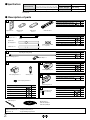
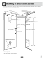
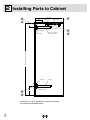
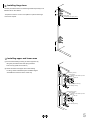
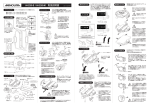
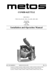
R
FAD-44、FAD-44L
Wooden Frame Type Instruction Manual
Thank you for selecting our product. Before starting installation,
please read this manual thoroughly to ensure correct installation.
Please keep this manual at hand for future reference.
■ About this product.
Lateral swing mechanism hardware that can be installed in narrow
spaces where a normally hinged door may not fit.
Ideal for tight from space applications
● When placing cabinets next to each other the front will be
completely flat when the door is closed.
● There is no need of embedding a rail on the floor.
● It is possible to adjust the door vertically (-3 to +7 mm), horizontally
(±7 mm), as well as in depth and parallel.
※In order to make it possible to adjust, make sure that the shelf board
can be detached for access.
■For your safety work and operation.
This symbol denotes prohibited actions.
This symbol denotes what must be done.
WARNING:
If these warnings are not followed, it may result in death or serious injury.
This (sliding door system) should be installed by an experienced person who has correct knowledge. If the system is not
installed correctly, the door will not operate smoothly, and or may cause injury.
It is necessary to manufacture the frame with sufficient strength so it endures the weight of the door and impact shocks
upon opening/closing the door. Also make sure to only use the designated screws and to fasten them firmly. A frame with
poor strength or loose screws might result in improper and slower movement of the door. In the worst case, the door might
drop down and cause injury.
Do not try to use this product for any other purposes than originally intended for. Do not use the parts for applications that
are out of specification.
Do not disassemble nor modify any parts other than those described in this document.
Caution
If these cautions are not followed, it may result in injury or damage.
This product is a part for cabinets. After installation, make sure to test the finished product thoroughly to ensure that it is
well-functioning and safe.
Make sure to follow the designated measurements and specifications as well as horizontal and verticals angles. Make sure
that frame and door are not warped nor bent, since it may affect the movement of the door.
If cutting any parts, make sure to remove any burr before installation.
Make sure to test the screws for slack at regular intervals (one month from first usage, half year and then one time every
year is recommended).
■ Notes on works
Handling of product
● The door is not supplied.
● After unpacking the product, check for damages on the parts.
●Specifications
From 750 mm to 800 mm*
Cabinet inside
measurement
* If the overlay distance on both sides of side plate
is 25 mm, the door width should be 800 to 850 mm.
Door height
Max. 2380 mm [2980 mm]
Door thickness
From 24 to 38 mm
Door weight
Max. 35 kg
Side plate thickness
Min. 25 mm
Note:Check that the cabinet side plate is constructed and assembled in the vertical direction. The size in [ ] applies to
the FAD-44L.
● Description of parts
1
Supplied Screw
Hinge base x 2
Support arm
nut x 1
Crank bracket
2
Support arm x 1
Upper arm
5
Countersunk self-tapping screw 4.5x30
12
タッピンねじ4.5 15.eps
タッピンねじ4.5×30.eps
Supplied (for assembling arm) Screw
Q'ty
Hexagon socket head cap screw M6x12
2
Spring washer
2
4
Cross-recessed bind self-tapping screw 4.5 x 20
(w/ stopper) x 1
Lower arm x 1
3
Countersunk self-tapping screw 4x20
Channel rail x 1
Gas spring
nut x 1
Q'ty
Clear cushion rubber
x1 + 1 (spare)
1_補助アーム組立
六角穴付ボルトM6×12.eps
2
ばね座金6.eps
Square nut M6(No need for this application)
四角ナットM6.eps
1_ 透明クッションゴム
Pipe length=1990 [2600]
Supplied Screw
1_上側,下側アーム
1_上側,下側アーム
Arm connecting pipe x 1
4
Flat washer
4
Pipe clamp x 1
4
六角穴付ボルトM6×12.eps
5
Supplied Screw
Bearing housing x 4
Gas spring holder x 1
Screw pin x 1
1_ガススプリング取付ブラケット
Q'ty
Hexagon socket head cap screw M6x35
Q'ty
Hexagon socket head cap screw M6x12
8
Spring washer
8
8
Square nut M6(No need for this application)
六角穴付ボルトM6×12.eps
ばね座金6.eps
6
1_ ベアリングハウジング
四角ナットM6.eps
Supplied Screw
Q'ty
16
Cross-recessed bind self-tapping screw 4.5 x 20
Conical springwasher x 1
1_ ねじ込みピン
Supplied Screw
M6
M8
Hexagon socket head cap screw M6x12
Positioning unit x 2
Q'ty
M10 2
Spring washer
2
Flat washer
2
7
1_ 位置調整ユニット
Parts to assemble support
arm 2 and positioning
unit 6 .
六角穴付ボルトM6×12.eps
E-ring
2
ばね座金6.eps
Square nut六角ナッ
M6(No need forト+平座金M10.eps
this application)
2
Gas spring x 1
Eリング6.eps
四角ナットM6.eps
■Tools used
- Phillips screwdriver No. 2 - Hexagonal wrench key 5
- Wrench 10, 16
- E-type retaining ring mounter
2
ガススプリング
Supplied Screw
M6
M8
Hexagon head bolt M10x150
Hexagon nut M10
Flat washer 10
M10
Q'ty
2
2
六角ボルトM10×150.eps
2
六角ナット+平座金M10.eps
Brush seal x 1
FAD-44: (5000)x1
FAD-44L: (6000)x1
1 Working in Door and Cabinet
Have a fixing screw pilot hole drilled in the cabinet or have that position marked precisely beforehand. Set core material of
which strength is enough for secure fixing to this part.
Prep
a
cros re hole
s-rec
f
esse or 4.5 x
d bin 20
d se
685
lf-tap
p
crew
170
20
5
20
ing s
59
378
Prepare hole for 4.5 x 20
cross-recessed bind self-tapping screw
Overl
a
allow ying
a
(hin nce
ged s
ide)
6
20
0
16 .5
2
10 5
4
Top board of cabinet
Two-dot chain line indicates inside
position of cabinet
70
70
(reference of working dimension)
80
70
Prepare hole for 4.5 x 20
30 cross-recessed bind self-tapping screw
110
39
15
Edge of door
39
130
36
Edge of cabinet
Prepare hole for 4.5 x 30
cross-recessed bind self-tapping screw
Hinged side
Approx 60
Rear face of door
Inside of cabinet side plate
Prepare hole for 4.5 x 20
cross-recessed bind self-tapping screw
30
180
70
290
80
70
110
70
Holes for handle
Left side hinged plan
Right side hinged plan can be symmetrical.
3
2 Installing Parts to Cabinet
(750−800)
206
Support arm
130
Channel rail
Bearing housing
Upper arm (w/ stopper)
(See Fig.
on P.5.)
Cabinet inside height max. 2340 [2940]
Hinge base
Gas spring holder
290
Hinge base
Lower arm
Bearing housing
Symbols from 1 to 4 shown in the figure indicate
the locations described below.
4
Use the provided screws to fix each hinge base temporarily to six
drilled holes on the cabinet.
130
1 Installing hinge base
Torque the screws in a criss-cross pattern to prevent the hinge
base to be warped.
Hinge base
290
Countersunk self-tapping screw
2 Installing upper and lower arms
(1) Fix the lower bearing housing to each hinge base by
using the provided screws and spring washers.
Tool: hex key (width across flats 5)
(2) Insert the shaft of the upper arm to the bearing
housing, which is identified by the installed stopper.
Assemble the lower arm in the same way.
Upper bearing housing
Spring washer
Hexagon socket head cap screw
M6×12
Upper arm
Stopper (upper side only)
Lower bearing housing
Upper bearing housing
Spring washer
Hexagon socket head cap screw
M6×12
Lower arm
Lower bearing housing
5
3 Installing channel rail
(1) Fix the channel rail to the top board with the provided screws.
(2) When screwing, tighten in order of ① to ⑤ as shown in the
right figure.
20
6
39
①
4
④
Installing Support arm and Gas spring holder
(1) Assemble the Support arm nut to the Support arm
crank bracket with the provided screws. Leave around 5 mm
of distance between the nut and the bracket.
Insert the Support arm nut to the channel rail and fix it at the
circle-marked position in the right figure.
③
Channel rail
⑤
②
Countersunk self-tapping
screws 4×20
Support arm square nut
Channel rail
Support arm
crank bracket
Gas spring
holder square nut
①
Spring washer
C
aution
・Be sure to fix the Support arm crank bracket to the direction
in the right figure.
Hexagon socket
head cap screw
M6×12
②
Support arm
Gas spring holder
Spring washer
(2) Assemble the Gas spring holder nut to the Gas spring holder
with the provided screws.
Leave around 5 mm of distance between the nut and the
holder.
Insert the Gas spring holder nut to the channel rail and fix it
at the circle-marked position in the right figure. (See ② .)
Position the Support arm in front of Gas spring holder as
shown in the right figure.
Hexagon socket head cap screw M6×12
Support arm
(3) Tape the Support arm temporarily so that it would
not interfere with the installation of the other parts.
Gas spring holder
6
3 Installing Arm Connecting Pipe
1 Cutting Arm connecting pipe
Cap
Clamp
(1) Pipe length = Cabinet inside height - 350
(This does not include the caps on both ends.)
(2) Cut the pipe end without the clamp.
Arm connecting pipe
(4) Replace the cap on the cut end.
Pipe length = Cabinet inside height – 350
(3) Remove burrs around the cutting edge to prevent injury and
enable smooth insertion of the cap.
Hexagon socket
head cap screw
M6×35
Flat washer
Upper arm
Arm connecting pipe
Cap
Hexagon socket
head cap screw
M6×35
Flat washer
2 Installing arm connecting pipe
Attach the Connection pipe to the cutout part on
both arms and fix it with the provided screws and flat
washers.
Torque the screws step by step, in a criss-cross
pattern, to prevent torsion of the pipe.
Cut this end
Cut out
Upper arm
Arm connecting pipe
Cut out
Arm connecting pipe
Pipe clamp
Cut out
Lower arm
Flat washer
Hexagon socket
head cap screw
M6×35
Arm connecting pipe
7
4 Installing Gas Spring
Gas spring
Upper arm
(w/ stopper)
8
Gas spring holder
Fixing Gas spring (arm side)
1 Installing Screw pin
Tighten the Screw pin firmly into the tapped hole on the top face of
the Upper arm.
Move the Upper arm to the full opening position where the
stopper touches the side board, then assemble the Gas spring
to the Screw pin as shown in the below figure.
Stopper
Open position
Screw pin
Spring washer
Viewed from the top of the cabinet.
E-ring
Flat washer
Gas spring
Upper arm
Upper arm
Screw pin
Spring washer
E-ring
Flat washer
Gas spring
Upper arm
Click
Upper arm
3
Fixing Gas spring holder
3-2.eps
Fixing Gas spring (top board)
Loosen the screws on the Gas spring holder a little.
Assemble the Gas spring to the Screw pin as shown in the
below figure.
With Upper arm at the full opened position where the stopper
touches the side board, tighten the screws on the Gas spring
holder firmly.
Attaching Clear cushion rubber
Gas spring holder
Gas spring
Flat washer
Return
Clear cushion rubber
the Upper arm to the closed position, then stick the
Clear cushion rubber on the center of the Upper arm stopper.
Upper arm stopper
E-ring
Gas spring holder
Gas spring
Flat washer
Clear cushion rubber
Upper arm stopper
E-ring
9
5 Installing parts to the door
Fixing Positioning unit
Mount the Positioning unit on the rear face of the door with
the provided screws so that the LAMP logo can be seen
properly.
CAUTION
Set core material of which strength is enough for secure tightening of self-tapping
screws to the locations that parts are to be installed.
Dimensions in lateral direction are determined with the (width) of the cabinet
(wooden frame) regarded as the reference position. If the door end face is
regarded as the reference position, add the overlaying allowance.
rogo can be seen
in the upright position
Ceiling
Reference of arm hinged side
Inside of cabinet
Cross-recessed bind self-tapping
screw 4.5 x 20
4-1.eps
Stick the Brush seal to both edges on the rear face of the door.
Door end side
Rear face of door
Sticking Brush seal
Rear face of door
brush seal
Floor surface
10
Hanging side
Positioning unit
6 Installing door
Assembling Upper and Lower
arms and Positioning unit
1. Open Upper and Lower arms to full opening position
as below.
The figure shows the Upper arm from underneath.
Support arm
Upper arm
(w/ stopper)
Upper
Positioning unit
Arm connecting pipe
Upper arm
Rear face of door
2. When hanging the door, place a support under the
door.
This is to protect the door and roughly match the
height of Upper and Lower arms and Positioning
units.
Pipe clamp
Positioning unit
Back face of the door viewed from
the inside of the cabinet
3. Hang the door in the following manner.
(1) Tighten the horizontal positioning screws on the
Upper and Lower positioning units.
(2) Align the top surfaces of the Upper and Lower
positioning units on the door with the bottom
surfaces of the Upper and Lower arms.
Hexagon head bolt
M10×150
(3) Insert a hexagon head bolt into the connecting
hole with the flat washer.
(5) Screw a hexagon nut into position until it touches
the positioning unit.
Flat washer
Connecting hole
Leave a
clearance here
Arm
10mm
(4) Screw the hexagon head bolt into the
positioning unit until its leading end protrudes
by about 10 mm.
Lower arm
Lower
Upper
Positioning unit
Up
pe
r
Lower
Lower
Hexagon nut M10
C
aution
Assemble the Upper arm and Upper positioning unit first, then
assemble the Lower arm and Lower positioning unit.
11
When positioning the door, be sure to loosen the hexagon socket head cap
screw on the Support arm crank bracket (see P. 6 ④ ) to allow the bracket to
move along the Channel rail.
2 Vertical positioning of door
Be sure that the side board of the cabinet is assembled in a
vertical direction.
1. Remove the support and close the door gently.
2. Measure the clearance between the top surface of the door
and the top board.
(1) The difference between the planned dimension and the
measurement is the required amount of adjustment.
(2) If there is no gap to correct, proceed to “ ③ Horizontal
positioning of door.”
(3) Replace the support in the original position and open the
door again.
・Loosen the hexagon head bolt on the Upper and Lower arms
a little.
・Refer to the right figure and adjust the height. After the
adjustment, turn the hexagon bolt on the Lower arm
clockwise.
・Close the door gently and check the height.
・If the height is OK, tighten the hexagon nut.
Caution
Note that there should be no gap between the Hexagon bolt and washer
for both Upper and Lower arms.
Vertical adjustment
Door
Hexagon head boltM10×150
Arm
Gap is not
allowed
Leave a
clearance here
Positioning unit
Tighten this hexagon nut after
vertical adjustment is complete.
Counter clockwise
360°
Clockwise
360°
1.5mm
Downward
1.5mm
Upward
If any gap is found, tighten the Hexagon bolts so that the load on the
two arms will be equal.
Arm
3 Horizontal positioning of door
1. Measure the horizontal gap between the door and cabinet.
If there is any gap to be corrected, loosen the Hexagon socket
head bolt on the Support arm crank bracket. (See P. 13 ④ .)
2. Loose the horizontal fixing screws on both Upper and Lower
positioning units.
3. Turn the horizontal positioning screws.
(1) Turn the screws clockwise to move the door to the left or
counterclockwise to move the door to the right when the
door is viewed from the front.
3
Positioning unit
Horizontal positioning
screws
Horizontal fixing screw
Horizontal positioning
2
(2) Retighten the positioning screws if the adjustment is OK.
Support arm crank bracket
Counter Clockwise
Clockwise
Clockwise
12
Right hanging
Counter Clockwise
Left hanging
Release Support arm crank bracket.
Loosen the hexagon socket head cap screws on the Support
arm crank bracket, and allow the bracket to move along the
Channel rail.
Hexagon socket head cap screw M6×12
Support arm crank bracket
Channel rail
Support arm
Support arm L-type
bracket
Fixing Support arm
Cross-recessed bind
self-tapping screw
4.5×20
Close the door completely, and fix the Support arm L-type
bracket to the door with provided screws.
Rear face of door
Be sure to face the pin of the crank bracket to
the rear of the cabinet.
Fix Support arm crank bracket.
Open the door slowly and fully and fix the Crank bracket.
When positioning the door, be sure to loosen the hexagon socket head cap screw on the Support arm crank bracket to allow
the bracket to move along the Channel rail.
Adjusting the gap between the side board and door.
Loosen the screws on the Lower arm which fix the Arm
connecting pipe.
While keeping the door closed with no gap between the door
and side board, retighten the screws.
If there is any gap left, adjust it by referring to "7
Troubleshooting【4】".
Rear face of door
Arm connecting pipe
Pipe clamp
Hexagon socket
head cap screw
M6X35
Lower arm
13
7 Troubleshooting
【1】Large friction sound when opening/closing door
Hexagon head bolt M10×150
Possible cause:
Positioning unit may touch the arm.
Solution:
Refer to P. 12 ② and make a clearance between the Positioning
unit and arm.
Arm
Leave a
clearance here
Positioning unit
【2】A gap remains between the side board and the door (hanging side) or it takes a long time to be closed.
Door end side
(1) In case of large gap
Hanging side
Possible cause:
The position of Crank bracket may be improper.
Solution:
Loosen the screws on the bracket and move the bracket to the
door-end direction. Then re-tighten the screws. (See P. 12.)
(2) In case of small gap
Possible cause:
Horizontal positioning of door may be improper.
Solution:
Loosen Horizontal fixing screws on the Positioning unit, then
adjust the position by rotating the Horizontal positioning screw.
Hexagon socket head
Cap screw M6×12
Support arm crank
bracket
Rear face of door
Arm
Horizontal
fixing screw
Positioning unit
Horizontal positioning
screws
Horizontal positioning
【3】Gap between door and cabinet varies after horizontal positioning
Solution:
Check the following in order.
(1) Vertical positioning, (2) Horizontal positioning (P.12), (3) Positioning of Crank bracket (P.13), and (4) Door close
position adjuster screw A, B (P.15)
Possible cause;
If you adjust the vertical position or horizontal position in the last order, the gap between the door and cabinet
may vary.
Connecting hexagon
head bolt
(1) Vertical positioning
Arm
Door end side
Hexagon socket head
cap screw A M6×35
Hanging side
Hexagon socket head
cap screw M6×12
Support arm crank
bracket
Door positioning unit
Horizontal positioning
screws
Horizontal positioning
14
(2)
Rear face of door
Hexagon socket head
cap screw B M6×35
Hexagon socket head
cap screw B M6×35
【4】Gap between door and cabinet still remains
Overview:
This system controls the slant of the door by
bowing the Connecting pipe.
Simply try the following method unsuspectingly.
Release the stress on Connecting pipe by
loosening the 4 pcs of Hexagon socket head
cap screws.
*Also, loosen Door close position adjuster
screw A and B, so that it make
a clearance
Loosen
between the Upper arm and the Connecting
pipe.
*Adjustment need to be done from inside the
cabinet at the closed door. Tighten
Tighten after
the adjustment
Tighten
Arm connecting
pipe
Hexagon socket head
cap screw A M6×35
Hexagon socket head
cap screw B M6×35
Hexagon socket
head cap screw
M6X35
Arm connecting
pipe
Gap at the top Loosen
Hexagon socket
head cap screw
M6X35
Tighten the Hexagon socket head cap screws on Lower arm.
Adjustment would not be achieved if the screws on Lower arm were
loose.
Tighten after
the adjustment
Arm connecting pipe
Gap at the bottom
Pipe clamp
Hexagon socket
head cap screw
M6X35
Lower arm
Tighten
Loosen
Tighten after
the adjustment
Tighten
Loosen
Arm connecting pipe
Hexagon socket
head cap screw
M6X35
Pipeapart
clamp from Upper arm, once loosen the Door
In case the gap still remains, even if the Connecting pipe is 7 or 8 mm
position adjuster screw A and B completely, then tighten them
until
the
Connecting pipe touches Upper arm. (See
Lower arm
below figure.)
Tighten after
the adjustment
Cross section C-C
CC
CC
Hexagon
Hexagonsocket
socket
headcap
headcapscrew
screwAA
M6×35
M6×35
Hexagon
Hexagonsocket
socket
headcap
headcapscrew
screwBB
M6×35
M6×35
15
【5】There are gaps on all four corners
Possible cause:
Large doors are likely to warp, and perfect adjustment is not
possible in case of a large warp.
Adjust the gap between the door and the cabinet by attaching
either the Brush seal or alternatively use "BS Bumpers" (sold
separately).
In case the door bows inward.
It is not possible to make more
than 2 corners to be contacted.
Brush seal
FAD-44:(5000mm)×1
FAD-44L:(6000mm)×1
In case the door bows outward.
It is not possible to make more
than a corner to be contacted.
BS Bumpers(sold separately)
You can choose various thickness.
【6】Out of alignment after using
Possible cause:
The position of the handle may be improper.
The arm may be bent or out of alignment due to improper opening
force if the handle is located far from the Hanging side.
Try the alignment.
If the parts are damaged. Contact us.
2014.06 PRINTED IN JAPAN 0216-3