1
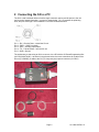
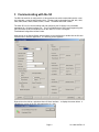
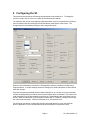
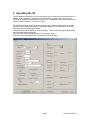
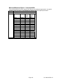
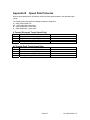
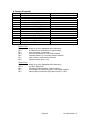
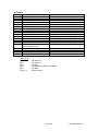
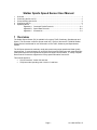
Stalker Sports Speed Sensor User Manual
1
2
3
4
5
Overview................................................................................................................................... 1
Connecting the S3 to a PC....................................................................................................... 2
Communicating with the S3...................................................................................................... 4
Configuring the S3.................................................................................................................... 6
Operating the S3 ...................................................................................................................... 7
Appendix A Command Packet Protocols ............................................................A-1
Appendix B Speed Data Protocols ......................................................................B-1
Appendix C Accessories......................................................................................C-1
1 Overview
The Stalker Speed Sensor (S3) is available in four types: Traffic, Stationary, Speedometer and
Sports. This document covers the Sports model only. Refer to document 011-0080-00 Stalker
Speed Sensor User Manual for user information on the Traffic, Stationary and Speedometer
models.
The S3 Sports operates in stationary mode and reports strong target speeds and faster (peak)
target speeds. It communicates over an RS-232 serial communications port with separate singleended transmit and receive signals and supports full-duplex communication. A variety of Speed
Data Protocol Formats are supported to convey speed information from the S3.
This manual applies to:
• S3 User Interface: Version 0.8 and later
• S3 Sports model operating code: Version 10 and later
Page 1
011-0081-00 Rev. B
2 Connecting the S3 to a PC
The S3 is a self-contained radar unit with a single connector used to provide power to the unit
and to monitor speed information. Its pinout is shown below. Pin 1 is between the polarizing
slots, and pins 2 through 5 are numbered in a counter-clockwise direction.
Pin 1 – RX – Receive Data – toward the S3 unit
Pin 2 – PWR – 12VDC (nominal)
Pin 3 – AUX – Auxiliary Input/Output
Pin 4 – TX – Transmit Data – from the S3 unit
Pin 5 – GND - Ground
The easiest way to start using an S3 is to connect it to a PC with the S3 Power/Programming Box
(ACI P/N 200-0702-00). As shown in the pictures below, there are connections for a cable to the
S3 unit (To RADAR), a cable to the PC (To Computer) and a power connector (9-12VDC).
Page 2
011-0081-00 Rev. B
Connect the S3 to the box with the 155-2223-00 cable provided with the box.
Connect to power by plugging the cigarette plug into a 12VDC nom. power supply.
And connect to a PC serial port using a standard 9 pin D Serial Cable (not provided).
Since some newer PCs are no longer configured with 9 pin D serial ports, a USB to serial adapter
may be required. These products vary and may or may not work well. In some cases they
provide undesirable buffering.
Page 3
011-0081-00 Rev. B
3 Communicating with the S3
The RS-232 serial link is configured for 10 bit asynchronous serial communications with 1 start
bit, 8 data bits, 1 stop bit and no parity (8N1). The baud rate is selectable from 300, 600, 1200,
2400, 4800, 9600, 19200, 38400, 57600, 115200. The default baud rate is 9600.
The basic PC tool for communicating with and configuring the S3 Sports is an executable
application file: “S3 User Interface.exe”. The CD provided with the S3 Power/Programming Box
(ACI P/N 200-0707-00) will install the file on the user’s PC in the “C:\Program
Files\Stalker\Configuration Utilities” folder.
After turning on the Speed Sensor with the switch on the interface box, double-click the S3 User
Interface icon to start the application. The following screen appears:
Right-click on the title bar, and select About S3 User Interface… to display the screen below. It
identifies the version of the PC utility application (e.g. 0.8).
Page 4
011-0081-00 Rev. B
To initiate communications with the S3, select the 9600 baud rate and appropriate communication
port from the pull-down boxes in the Comm Settings area of the screen in the top-left corner.
Then click on the Connect button in the lower-left corner. And finally click the Get Config button
to poll the unit and display its current settings:
If the unit is not communicating, confirm the communication port and baud rate settings from the
pull-down menu.
The version of operating code loaded into the S3 Sports will be displayed in the Software Version
window near the lower-right corner of the screen (e.g. 10).
The software version is also displayed in the “t format” area after clicking the Self Test button at
the bottom of the screen. After a self test, a result code is also displayed in this area – “0” means
all tests passed.
Page 5
011-0081-00 Rev. B
4 Configuring the S3
This section assumes that the S3 already has operational code loaded into it. To change the
version of code in the S3, refer to 011-0054-00 LoadCode User’s Manual.
The settings in the unit can be changed by selecting another value from a parameter’s pull-down
menu as shown below and clicking the Send Data button at the bottom of the screen. The
changes may be confirmed by clicking the Get Config button again.
When the Send Data button is clicked, the PC application sends a command to change only a
single parameter. If multiple settings need to be changed, the Send Data button must be clicked
after each change.
Since the S3 reports speed data while the radar transmitter is on, it is best to turn the transmitter
off while changing settings so that the serial communications aren’t overloaded. The status of the
radar transmitter may be determined by monitoring the Transmit/Hold button at the bottom of the
screen. While the transmitter is off, the legend on this button is “Transmit” (clicking it now will put
the unit into transmit mode). While the transmitter is on, the legend is Hold.
The S3 Sports can also be configured by sending command packets to it over the serial link.
Refer to Appendix A for the command structures and descriptions of parameter values.
Page 6
011-0081-00 Rev. B
5 Operating the S3
The PC application described in the previous section can be used to monitor speeds that the S3
detects. Other equipment or applications can also monitor the speed data from the unit by
decoding the messages it transmits over the serial link. Speed data is only sent from the S3 unit
while the radar transmitter is on (unit not in Hold).
The S3 Sports supports several streaming message types. Refer to Appendix B for a detailed
description of the speed data protocols. Speeds are displayed on the right side of the screen
depending on the message type selected:
Format A and AP speeds display in the A format area. Format A shows strongest target speed,
and Format AP shows peak speed.
Format b and Format S speeds display in their respective areas.
Format F is a development protocol not supported in this application.
Page 7
011-0081-00 Rev. B
Appendix A
Command Packet Protocols
Received Data Packet Format
The format for all received packets is shown below:
Byte #
Description
1
Command ID
2
Message Data
…
Message Data
N-1
Message Data
N
Carriage Return (0x0D)
The number of message data bytes is implicit in the command type so there is no data byte count
in the packet. Packets do not necessarily have data associated with them so the minimum
packet size is two bytes consisting of the Command ID and a carriage return. Message Data
bytes, unless otherwise specified, are ASCII characters: ‘1’ = ASCII 1 = 0x31.
Message Type – Command 81H
Byte #
1
2
3
Description
0x81
Message Type =
0x20 – No Output
0x21 – A Format
0x22 – b Format
0x30 – S Format
0x40 – AP Format
Carriage Return (0x0D)
Auto Repeat Message Delay – Command 82H
Byte #
Description
1
0x82
2
Delay ten thousands digit (ASCII)
3
Delay thousands digit (ASCII)
4
Delay hundreds digit (ASCII)
5
Delay tens digit (ASCII)
6
Carriage Return (0x0D)
The delay parameter specifies the total time in milliseconds between the start of successive
messages. A Delay of ‘0000’ causes the next message to immediately follow the carriage return
of the previous message. In specifying a message repeat rate, there are three constraints that
place a lower limit on the repeat rate:
1. RS-232 baud rate
2. The rate at which the DSP algorithms produce new speed data
3. The radar transmitter must be enabled.
Page A-1
011-0081-00 Rev. B
Transmit/Hold – Command 93H
This command instructs the S3 to enable or disable the radar transmitter. The user only receives
speed data packets when the transmitter is enabled. When the S3 is powered on, the transmitter
is automatically enabled by default.
Byte #
Description
1
0x93
2
‘0’ = Hold
‘1’ = Transmit
3
Carriage Return (0x0D)
Radar Directional Mode – Command 94H
Byte #
1
2
3
Description
0x94
‘1’ = Closing – only report speed of targets moving towards the S3
‘2’ = Away – only report speed of targets moving away from S3
‘3’ = Bi-directional – report speed of targets moving in either direction
Carriage Return (0x0D)
Sensitivity – Command 96H
Byte #
Description
1
0x96
2
‘1’ , ‘2’ , ‘3’ , ‘4’ , ‘5’ , ‘6’ , ‘7’ , ‘8’
3
Carriage Return (0x0D)
The S3 has two overall sensitivity settings: LOW and HIGH. And within each overall setting, four
additional sensitivity levels are available. Therefore settings 1-4 correspond to LOW sensitivity
while settings 5-8 correspond to HIGH sensitivity.
Test – Command 99H
Byte #
Description
1
0x99
2
Carriage Return (0x0D)
This command instructs the S3 to stop transmitting, turn off the auto repeat message delay, and
to perform an internal self test. After the self test is complete the S3 sends a response in the
format below and enters tuning fork test mode for 1 minute.
Test Response Packet – t format
Byte #
1
2
3-6
7
Description
0x84
Test result code (0 = pass)
Software version in 4 ASCII bytes
Carriage Return (0x0D)
Page A-2
011-0081-00 Rev. B
AUX Pin – Command A2H
This command allows the user to enable or disable output on the AUX pin of the external
connector. This pin can either be used to output Doppler audio or speed threshold alarms. Note
(1) the AUX pin is read as an input on power-up to check whether factory defaults should be
restored, and (2) the factory default is that the AUX pin is disabled for output. When used as a
speed alarm, the AUX pin can source a maximum of 10mA at 3.3V.
Byte #
Description
1
0xA2
2
‘0’ = Disable AUX output
‘1’ = Speed Alarm
‘2’ = Doppler Audio without Squelch
‘3’ = Doppler Audio with Squelch
3
Carriage Return (0x0D)
Alarm Speed Threshold – Command A3H
The S3 allows the user to set an alarm speed threshold specified in whole numbers in the range
of 1-309 MPH. This can only be set immediately after the gun is turned on.
Byte #
Description
1
0xA3
2
Alarm speed hundreds digit (ASCII)
3
Alarm speed tens digit (ASCII)
4
Alarm speed units digit (ASCII)
5
Carriage Return (0x0D)
Serial Port Baud Rate – Command A4H
The serial port baud rate may be set in the range of 300-115200. The parameter change will take
effect after the next time the S3 is powered on.
Byte #
Description
1
0xA4
2
Baud rate code:
‘0’ = 300
‘1’ = 600
‘2’ = 1200
‘3’ = 2400
‘4’ = 4800
‘5’ = 9600
‘6’ = 19200
‘7’ = 38400
‘8’ = 57600
‘9’ = 115200
3
Carriage Return (0x0D)
Peak Speed Mode – Command A5H
This command allows the user to enable or disable calculation of the peak speed.
Byte #
Description
1
0xA5
2
‘0’ = disable
‘1’ = enable
3
Carriage Return (0x0D)
Page A-3
011-0081-00 Rev. B
Speed Resolution – Command A7H
Byte #
1
2
3
Description
0xA7
‘0’ = units
‘1’ = tenths
Carriage Return (0x0D)
Speed Units – Command A8H
Byte #
1
2
3
Description
0xA8
‘0’ = MPH
‘1’ = KPH
‘2’ = KNOTS
‘3’ = FPS
‘4’ = MPS
Carriage Return (0x0D)
Directionality – Command A9H
This command allows the user to specify the directionality parameter that the radar uses to
qualify directional true targets from non-directional spurious signals. This parameter can take any
integer value in the range of 0 to 7 inclusive where the parameter is understood to represent the
corresponding power of two. The target must be greater than or equal to 2 to the parameter
value of the corresponding FFT bin of the other spectrum. This yields a settable range of 0-42dB.
Byte #
Description
1
0xA9
2
‘0’ , ‘1’ , ‘2’ , ‘3’ , ‘4’ , ‘5’ , ‘6’ , ‘7’
3
Carriage Return (0x0D)
Auto Clear Delay – Command AAH
Byte #
1
2
3
Description
0xAA
‘0’ = 0 seconds
‘1’ = 1 second
‘2’ = 2 seconds
‘3’ = 3 seconds
‘4’ = 4 seconds
‘5’ = 2.33 hours
Carriage Return (0x0D)
Page A-4
011-0081-00 Rev. B
Minimum/Maximum Speed – Command ABH
This command allows the user to specify the minimum and maximum target speed. Any speed
outside the range is ignored. Also Baseball and Tennis modes are implicitly set as well.
Byte #
Description
1
0xAB
2,3,4
Parameter Mode
Min
Max
Speed
Speed
(MPH)
(MPH)
‘000’
Normal
0
140
‘001’
Normal
5
140
‘002’
Normal
15
140
‘003’
Normal
25
140
‘004’
Normal
50
140
‘005’
Normal
0
- (none)
‘006’
Normal
5
‘007’
Normal
15
‘008’
Normal
25
‘009’
Normal
50
‘010’
Baseball 10
110
‘011’
Baseball 20
110
‘012’
Baseball 30
110
‘013’
Baseball 40
110
‘014’
Baseball 50
110
‘015’
Tennis
50
148
5
Carriage Return (0x0D)
Speeds in KPH are MPH readings x 1.609.
Page A-5
011-0081-00 Rev. B
Appendix B
Speed Data Protocols
When a speed data protocol is selected, the S3 will send speed updates in the selected output
format.
The following streaming protocol message formats are supported:
A – ASCII target speed only
AP – ASCII peak target speed only
B – ASCII All speeds + some status
S – ASCII All speeds + some status
A Format (Strongest Target Speed Only)
Byte #
1
2
3
4
Description
Target speed hundreds digit (ASCII)
Target speed tens digit (ASCII)
Target speed ones digit (ASCII)
Carriage Return (0x0D)
AP Format (Peak Target Speed Only)
Byte #
1
2
3
4
Description
Peak speed hundreds digit (ASCII)
Peak speed tens digit (ASCII)
Peak speed ones digit (ASCII)
Carriage Return (0x0D)
Page B-1
011-0081-00 Rev. B
b Format (all speeds)
Byte #
1
2
3
4
5
6
7
8
9
10
11
12
13
14
15
16
Description
Message Type
Status 1
Status 2
Patrol speed hundreds digit (ASCII)
Patrol speed tens digit (ASCII)
Patrol speed ones digit (ASCII)
Locked speed hundreds digit (ASCII)
Locked speed tens digit (ASCII)
Locked speed ones digit (ASCII)
Peak speed hundreds digit (ASCII)
Peak speed tens digit (ASCII)
Peak speed ones digit (ASCII)
Target speed hundreds digit (ASCII)
Target speed tens digit (ASCII)
Target speed ones digit (ASCII)
Carriage Return (0x0D)
Required Value or Range
0x81
(see detail below)
(see detail below)
0x0D
Status 1 byte
Bit 7-6:
Bit 5:
Bit 4:
Bit 3:
Bit 2:
Bit 1:
Bit 0:
always 01 (to force displayable ASCII characters)
lock status (0=no speed locked, 1=speed locked)
zone (0=opposite, 1=same/both)
fork mode (0=off/normal, 1=fork mode enabled)
secondary antenna (1= secondary antenna selected)
main antenna (1=main antenna selected)
transmitter status (0=off, 1=on)
Status 2 byte
Bit 7-6:
Bit 5-3:
Bit 2:
Bit 1:
Bit 0:
always 01 (to force displayable ASCII characters)
not used - always 000
fast status (0=faster disabled, 1=faster enabled)
Low voltage (LoV) status (0=normal, 1=low voltage condition)
radio frequency interference (RFI) Status (0=none, 1=RFI)
Page B-2
011-0081-00 Rev. B
S Format
Byte #
1
2
3
4
5
6
7
8
9
10
11
12
13
14
15
16
17
18
19
Description
Message type
Peak target direction
Peak target speed
(same)
(same)
(same)
Strongest target direction
Strongest target speed
(same)
(same)
(same)
Log of current speed
(same)
(same)
Log of current speed
(Pos. Freq/Neg. Freq)
(same)
(same)
Status
Carriage return
Required Value or Range
0x83
‘A’ = “away”, ‘C’ = “closing”
Hundreds (100)
‘0’ – ‘9’ (ASCII)
Tens (10)
‘0’ – ‘9’ (ASCII)
Ones (1)
‘0’ – ‘9’ (ASCII)
Tenths (0.1)
‘0’ – ‘9’ (ASCII)
‘A’ = “away”, ‘C’ = “closing”
Hundreds (100)
‘0’ – ‘9’ (ASCII)
Tens (10)
‘0’ – ‘9’ (ASCII)
Ones (1)
‘0’ – ‘9’ (ASCII)
Tenths (0.1)
‘0’ – ‘9’ (ASCII)
Hundreds (100)
‘0’ – ‘9’ (ASCII)
Tens (10)
‘0’ – ‘9’ (ASCII)
Ones (1)
‘0’ – ‘9’ (ASCII)
Hundreds (100)
‘0’ – ‘9’ (ASCII)
Tens (10)
Ones (1)
(see detail below)
0x0D
‘0’ – ‘9’ (ASCII)
‘0’ – ‘9’ (ASCII)
Status byte
Bit 7:
Bit 6:
Bit 5:
Bit 4:
Bit 3:
Bits 2,1,0:
not used (= 0)
not used (= 1)
not used
Fork Mode (1=enabled, 0=disabled)
not used
Antenna Errors
Page B-3
011-0081-00 Rev. B
Appendix C
Accessories
ACI P/N
200-0702-00
Accessory
S3 Programming Box Kit
155-2223-00
S3 Power and I/O Cable, 12’ **
155-2227-00
S3 Power I/O User Cable **
200-0707-00
S3 Applications CD **
155-2226-00
S3 Power and I/O Cable, 75’
155-2252-00
S3 Extension Power I/O Splitter
Cable
200-0708-00
S3 Cable Connector Kit
155-2225-75
S3 to Speed Sign Cable
Description
Along with the programming box itself, items
with ** after their name are included in this kit.
Provides cigarette plug for power, connections
for S3 and serial cables, on/off switch, reset
button and auxiliary I/O access
Standard 12’ cable used to connect the S3 to
the Programming Box or to a 155-2227-00
cable for a user-defined interface
Can be used to interface S3 with 155-2223-00
cable to user-developed power and I/O
connections
CD containing user applications and
associated files
Connects to S3 providing round connector on
the distant end
Mates with round connector on 155-2226-00
cable to extend it by approximately 8’, and
provides a cigarette plug for power and a
direct connection to a computer serial port
Includes a panel mount connector, socket
contacts and a wiring diagram so user can
wire 155-2226-00 cable into their system –
used in lieu of 155-2252-00.
Connects the S3 to an ACI Speed Sign
Page C-1
011-0081-00 Rev. B