1
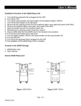
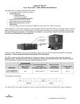
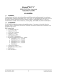
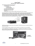
User’s Manual
The RS232 Multi-Port Card provides a way to turn a single UPS’s RS232 serial port into three separate RS232 serial
ports. This allows the user to perform a safe and logical shutdown on three servers or workstations simultaneously by
using power management software. Only one of the three computers can control the UPS, the other two computers can
only monitor the status of the UPS. Connect the RS232 DB9 female to male serial cable to the computer that is going to
control the UPS. Connect the two RS232 DB9 female to RJ45 cables to the two computers that are going to monitor the
status of the UPS. Load the power management software on all three computers. See the power management software
User’s Manual to setup the shutdown feature. There are two status LEDs on the front panel. The Red LED indicates that
there is power to the RS232 Multi-Port Card. The Green LED indicates the working status of the RS232 Multi-Port Card.
When the Green LED is blinking everything is normal, when the Green LED is off or on solid this indicates that there is a
problem.
Internal RS232 Multi-Port Card
UPS
Figure 1 Internal RS232 Multi-Port Card
Installation Procedure of the Internal RS232 Multi-Port Card
1.
2.
3.
4.
5.
6.
7.
8.
9.
10.
11.
Turn off all the equipment that is plugged into the UPS.
Turn off the UPS and unplug the UPS’s power cord from the wall outlet.
Remove the two retaining screws from the option slot’s cover plate (rear panel of the UPS).
Remove the option slot’s cover plate. (rear panel of the UPS).
Insert the RS232 Multi-Port Card into the option slot.
Install the two retaining screws (provided with the RS232 Multi-Port Card package).
Plug in the DB9 cable from the RS232 Multi-Port Card to the computer that will be controlling the UPS.
Plug in the two RJ45 cables from the RS232 Multi-Port Card to the two computers that will be monitoring the UPS.
Plug the UPS’s power cord into the wall outlet.
Turn the UPS and your equipment ON.
The RS232 Multi-Port Card is operational.
Page 1 of 3
34000192 Rev0
Contents of the Internal RS232 Multi-Port Card Package
1. RS232 Multi-Port Card.
2. Two retaining screws.
3. One DB9 Male-to-Female Serial Cable (connects from the RS232 Multi-Port Card’s RS232 connector to the
computer).
4. Two DB9 Female to RJ45 Cables (connects from the RS232 Multi-Port Card’s RJ45 connectors to the computers).
5. User’s Manual.
External RS232 Multi-Port Card
UPS
Power
Adapter
External RS232
Multi-Port Card
Serial UPS cable
Figure 1 External RS232 Multi-Port Card
Installation Procedure of the External RS232 Multi-Port Card
1.
2.
3.
4.
5.
6.
7.
8.
9.
10.
11.
12.
13.
Turn off all the equipment that is plugged into the UPS.
Turn off the UPS and unplug the UPS’s power cord from the wall outlet.
Plug the power adapter’s connector into the connector, on the external adapter box, labeled “Input”.
Plug the DB9 Male to Female serial cable into the connector, on the external adapter box, labeled “To UPS”.
Plug the other end of the DB9 Male to Female serial cable into the Serial Port on the UPS.
Plug the power adapter into one of the Battery Powered outlet of the UPS.
Insert the RS232 Multi-Port Card into the External Box.
Install the two retaining screws (provided with the External RS232 Multi-Port Card package).
Plug in a DB9 cable from the RS232 Multi-Port card to the computer that will be controlling the UPS.
Plug in the two RJ45 cables from the RS232 Multi-Port Card to the two computers that will be monitoring the UPS.
Plug the UPS’s power cord into the wall outlet.
Turn the UPS and your equipment ON.
The RS232 Multi-Port Card is operational.
Contents of the External RS232 Multi-Port Card Package
1.
2.
3.
4.
5.
6.
7.
8.
RS232 Multi-Port Card.
Two retaining screws.
External Box.
Power Adapter.
DB9 Male-to-Female Serial Cable (connects from the RS232 External Box’s RS232 connector to the UPS).
DB9 Male-to-Female Serial Cable (connects from the RS232 Multi-Port Card’s RS232 connector to the computer).
Two DB9 Female to RJ45 Cables (connects from the RS232 Multi-Port Card’s RJ45 connectors to the computers).
User’s Manual.
Page 2 of 3
34000192 Rev0
LIMITED PRODUCT WARRANTY
Para Systems Inc. (Para Systems) warrants this equipment, when properly applied and operated within specified
conditions, against faulty materials or workmanship for a period of three years from the date of original purchase by the
end user. For equipment sites within the United States and Canada, this warranty covers repair or replacement of
defective equipment at the discretion of Para Systems. Repair will be from the nearest authorized service center.
Replacement parts and warranty labor will be borne by Para Systems. For equipment located outside of the United States
and Canada, Para Systems only covers faulty parts. Para Systems products repaired or replaced pursuant to this
warranty shall be warranted for the remaining portion of the warranty that applies to the original product. This warranty
applies only to the original purchaser who must have properly registered the product within 10 days of purchase.
The warranty shall be void if (a) the equipment is damaged by the customer, is improperly used, is subjected to an
adverse operating environment, or is operated outside the limits of its electrical specifications; (b) the equipment is
repaired or modified by anyone other than Para Systems or Para Systems-approved personnel; or (c) has been used in a
manner contrary to the product's operating manual or other written instructions.
Any technical advice furnished before or after delivery in regard to use or application of Para Systems’s equipment is
furnished without charge and on the basis that it represents Para Systems’s best judgment under the circumstances, but it
is used at the recipient's sole risk.
EXCEPT AS PROVIDED HEREIN, PARA SYSTEMS MAKES NO WARRANTIES, EXPRESSED OR IMPLIED,
INCLUDING WARRANTIES OF MERCHANTABILITY AND FITNESS FOR A PARTICULAR PURPOSE. Some states do
not permit limitation of implied warranties; therefore, the aforesaid limitation(s) may not apply to the purchaser.
EXCEPT AS PROVIDED ABOVE, IN NO EVENT WILL PARA SYSTEMS BE LIABLE FOR DIRECT, INDIRECT,
SPECIAL, INCIDENTAL, OR CONSEQUENTIAL DAMAGES ARISING OUT OF THE USE OF THIS PRODUCT, EVEN IF
ADVISED OF THE POSSIBILITY OF SUCH DAMAGE. Specifically, Para Systems is not liable for any costs, such as lost
profits or revenue, loss of equipment, loss of use of equipment, loss of software, loss of data, cost of substitutes, claims
by third parties, or otherwise. The sole and exclusive remedy for breach of any warranty, expressed or implied,
concerning Para Systems’s products and the only obligation of Para Systems hereunder, shall be the repair or
replacement of defective equipment, components, or parts; or, at Para Systems’s option, refund of the purchase price or
substitution with an equivalent replacement product. This warranty gives you specific legal rights and you may also have
other rights, which vary from state to state.
Longer term and F.O.B. job site warranties are available at extra cost. Contact Para Systems (1-972-446-7363) for
details.
Page 3 of 3
34000192 Rev0