1
Merlin Systems Corp. Ltd
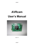
MIABOT BT v5.x
User Manual
Rev. 2.3
i
!
$%
&'
(
"
#
!
#
#
"
Merlin Systems Corp. Ltd assumes no responsibility for any errors which may appear
in this manual, reserves the right to alter the devices, software or specifications
detailed herein at any time without notice, and does not make any commitment to
update the information contained herein. Merlin Systems Corp. Ltd’s products are not
authorized for use as critical components in life support devices or systems.
ii
Introduction....................................................................................................................4
Quick Start .................................................................................................................4
Specification ..............................................................................................................5
Rear View ..................................................................................................................6
Underside View .........................................................................................................7
Internal Views............................................................................................................8
Shaft Encoders ...........................................................................................................8
Drive Chain................................................................................................................9
Batteries .....................................................................................................................9
Communications Board .............................................................................................9
Bluetooth Communications .........................................................................................10
Verifying Robot Communication ............................................................................11
Bluetooth Links........................................................................................................11
Note on Multiple Links.........................................................................................11
Standard Code Command Protocol..........................................................................12
Simple commands................................................................................................12
Distance-controlled ('
BIGTRACK'style)............................................................12
Step movement.....................................................................................................13
Speed control .......................................................................................................13
Saved Parameters .................................................................................................14
Sequence controls ................................................................................................15
Expansion I/O ......................................................................................................16
Bigtrack Simulator .......................................................................................................17
Line Follower...............................................................................................................18
Sensor Board and Mechanics...................................................................................18
Application...............................................................................................................19
Communications ..................................................................................................19
Manual Operation ................................................................................................19
Line Following.....................................................................................................19
Sensors .................................................................................................................19
Tracking Controls ................................................................................................20
Robot Firmware Development.....................................................................................21
Overview..................................................................................................................21
Compiler Installation ...............................................................................................21
Programming............................................................................................................21
Writing Robot Programs ..........................................................................................25
3
Introduction
The MIABOT is a fully autonomous miniature mobile robot. The latest MIABOT-BT
edition features bi-directional Bluetooth communications, which provides a robust
frequency hopping wireless communications protocol at 2.4GHz.
MIABOTs are ideal robots for use as part of technology class tutorials, for research
and development. Universities already use MIABOTs worldwide for a wide variety of
applications including FIRA robot soccer competitions, intelligent behaviours, robot
swarming experiments and mobile robot navigation experiments. Miabots can also be
employed as super mice, for line/maze following experiments etc.
Quick Start
Each robot is supplied with a built in demonstration program: Turn off, move all the
dip switches at the back of the robot to the ON position, make sure robot has plenty of
space, then turn it on. Remember to reset the switches so the robot does not start the
test sequence next time it is turned on!
You can also drive the robot directly using the command protocol (see later section)
or one of the supplied application programs such as Bigtrack BT.
4
Specification
MIABOT-BT
Processor
Memory
Speed
Flash
SRAM
E2
Features
Expansion Port
Dual Drive Train
Speed
Communications
Batteries
Development
Simulator
Atmel ATMega8
8K Flash
8 MIPS (RISC)
8Kbtye
1Kbyte
512 bytes
In System Programmable
Hardware Multiply
Self Programming Feature (useful for
adaptive learning)
8 × digital I/O or 10 Bit A/D inputs
Optical encoders with a resolution of
0.8mm
1m/s
Bluetooth
Rechargeable 8 x 1.2V NiMH
Standard toolset includes GCC ‘C’
compiler & linker
FIRA Simulation Engine
5
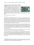
Rear View
(connections and controls are all at the rear)
LED1 and LED2 are under software control, with 330ohm inline resistors provided.
In normal use, LED1 flashes continually when switched on: LED2 lights when a
command is being received.
When the robot reboots (e.g. power-on), the LEDs flash a brief test sequence.
The programming cable provided can be plugged into the expansion port, connecting
the robot to a PC parallel port for rewriting the robot firmware.
The 4-way DIL switch is connected to micro pins (see appendix B) and can be read
under software control.
6
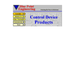
Underside View
The underside looks like this –
The Expansion Port pins connect directly to Atmel Mega8 CPU pins ADC0->ADC7,
and certain other signals (see schematic). GND, +5v and battery supply voltage are
also provided on this connector.
The charge socket and plates connect direct to the battery, allowing the robot to be
charged whether switched on or off.
7
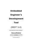
Internal Views
By removing the 4 plastic snap rivets in the corners the case (top) can be removed –
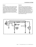
Shaft Encoders
The motor shaft is driven via a worm drive such that the motor shaft turns 16 times
per 1 turn of the wheel. The wheels are 32.5mm in diameter, so one interrupt hole on
the encoder disk corresponds to just under 0.8mm of movement.
The connection circuit is arranged as follows –
8
The outputs produce negative-going pulses on open-collector outputs, which are
connected to the INT0 and INT1 (interrupt-capable) pins on the Atmel processor.
Drive Chain
The drive train is driven by 8 x 1.2v (AA) cells through a driver I.C., with a voltagedrop of about 2.5V (typical, full-speed), equivalent to a nominal drive of about 7-8V.
Batteries
Each robot contains two 4×AA-cell battery packs (nominal 1.2v per cell, 600mAh).
The robot is supplied with a NiMH fast-charger that can charge these completely in
about 1hr. Batteries will last about 1hr typical continuous use (much more if not
moving!). Higher-capacity batteries are also available in the same physical size.
Communications Board
The Bluetooth card enables the robot to communicate with the host PC, converting the
Bluetooth link to logic-level serial signals –
The MIABOT-BT bluetooth boards are supplied with fixed communication settings 19200 baud (8 bits,1 stop bit, no parity).
A PC Bluetooth dongle is supplied that plugs into the USB port on the PC.
This can support wireless links with up to 7 robots at once.
9
Bluetooth Communications
Follow the manufacturers instructions (included) to install the PC dongle.
Once installed, double click on the Bluetooth icon (bottom right hand corner). This
will bring up an explorer window showing “My Bluetooth Places”.
Make the ‘folders’ view visible, and click on “Entire Bluetooth Neighbourhood”.
Then select “Bluetooth\Search for Devices”, and wait while the machine scans for
available contacts.
If the robot is turned on and in range you should get a window looking somewhat like
this –
The robot is the device called “mid100”: MIABOT communications modules are all
identified as “mid<X>” , where <X> is a serial number.
To link to the robot, first right click on the icon and select “Pair Device”.
At this point you will be prompted to enter a password, by clicking on the blue tray
icon (bottom right): Key in the pass code “1234”.
Right click again and select “Discover Available Services”, which should after a short
wait come back with something like “SPP slave” or “Bluetooth Serial Port”.
Right click on the icon once more, and select “Connect to Bluetooth Serial Port” (or
similar), and the robot is connected to a virtual COM port.
The identity of the COM port now appears in the status bar at the bottom of the
explorer window, or can be found from right-click, “Properties” on the icon.
The device icon is highlighted (usually green) when connected.
(N.B. The actual COMport number will depend on the order of connecting, and other
devices in your system).
10
NOTE: this is a ‘safe’ connection method: The process can be made simpler once
you are confident of the details. (Unfortunately, the precise operation depends on the
version of the Bluetooth tray software and the operating system in use).
Verifying Robot Communication
It is a good idea to confirm that communications have been established by using a
terminal program such as Hyperterminal.
Set up a new connection to connect to the appropriate COM port (e.g. COM4): Most
of the ordinary serial settings have no effect, but ensure that “no handshaking” is
selected.
Within the Hyperterminal “Settings” tab, “ASCII setup” page, it is best to set “Send
line ends with line feeds” and “Echo typed characters locally”.
Connect, and type a command like “[t]”, and the robot should then respond with a
signon message e.g. “<MIABOT OS v5.0 : id=00>”.
This command response contains the robot ID, set by the switches at the back of the
robot.
You can try various other commands by referring to the available commands listed in
the “Standard Command Protocol” section, below.
Bluetooth Links
Each Bluetooth link is a dedicated, secure two-way channel established exclusively
between the two devices (the ‘pairing’).
It appears to PC applications programs as a “virtual COMport”, which can be
connected to much like an ordinary serial port. At the robot end, it appears as logiclevel serial signals.
The PC dongle acts a Bluetooth ‘master’ device (which can establish links) while
each robot is a separate ‘slave’ device. A slave device can only be paired with one
master at any one time.
If radio contact is lost, the link will be automatically restored when it is regained.
However, whenever the robot or computer is powered off, the link must generally be
re-established, including re-typing the password.
Note on Multiple Links
To connect to more than one robot you may need to configure extra virtual serial
ports. The steps required vary, depending upon the Bluetooth host software installed,
but here is an example :- Right-click on the Bluetooth tray icon, select ‘Advanced Configuration’.
- Select “Client Applications”. At the bottom of the panel should be a button “Add
COM port”: After selecting this, enter a name for the connection e.g. “MIABOT1”
and select an available COM port (i.e. a currently unused number).
- Repeat this for each additional COM port required.
11
Standard Command Protocol
These are the commands supported by the standard robot control software.
( N.B. the example source code supplied is somewhat simpler, and may not contain all
these commands )
All commands begin with the command-start character '
['
, and end with the commandend character '
]'
. The first character after '
['identifies the command, after that bytes
are free-format, determined by the specific command used.
Extra characters after command-arguments and before '
]'are ignored and extra
characters between commands (after '
]'and before '
['
) are also ignored.
When the processor starts up or reboots, the robot emits the sign-on message e.g.
"<MIABOT OS v2.0 : id=01>", plus some carriage-return / linefeed characters.
Commands recognised and executed can be echoed back, bracketed in '
<'and '
>'
rather than '
['and '
]'(see ‘Saved Parameters’ section).
Some commands produce other output, usually also enclosed in ‘<>’.
Unrecognised commands are always ignored.
Simple commands
[s] - "stop"
Set both wheel speeds to 0
[t] - "test"
Test comms, returns the signon string which also contains the robot-id, read from the
DIL switched on reboot. E.G. "<MIABOT OS v2.0 : id=03>" for robot 3.
[NOTE: if id=15 the robot runs the default test sequence on powerup]
[!] - "flash"
Flash LEDs in power-up sequence (both,#1,#2,neither)
Distance-controlled ('BIGTRACK' style)
Turn at set turn-rate, or move forward/backward at set movement-rate (see '
x'
command, below).
[m<$>] - "left by"
[n<$>] - "right by"
[o<$>] - "forward by"
[p<$>] - "backward by"
<$> is a single binary byte, 0-255
Both wheels are set to run backward/forward by <#> encoder steps, after which the
relevant motor stops. Wheels run independently and a distance of zero means '
forever'
[x<?><#>] - "set movement rate"
Control set power-level for all movement or turn operations.
12
<?> is a movement-type character: '
<'or '
>'to set turn-rate, '
^'or '
v'to set
movement-rate
<#> is a decimal number, read as a power setting in the range 0-127
Step movement
[<] - "step left"
[>] - "step right"
[^] - "step forward"
[v] - "step backward"
Rotate or move forward/backward by set distances. As for distance commands,
wheels run independently, and at set speeds (‘x’ command).
[d<?><#>] - "set step distance"
Control step-distance to move (forward/backward) or turn (left/right) for all '
step'
commands
<?> is a movement-type character: '
<'or '
>'to set turn-step, '
^'or '
v'to set
movement-step
<#> is a decimal number, setting the number of encoder steps 0..65535
[?] - "enquire whether step is running"
Return either “<?=1>”, while step movement is still running, or “<?=0>” if none
(robot at rest, or under speed control).
Speed control
[-<$l><$r>] - "set speed"
Set wheel speed (binary). Speeds apply forever until cancelled.
<$l>is a single binary byte, controlling left wheel speed -128..+127
<$r>is a single binary byte, controlling right wheel speed -128..+127
[=<#l>,<#r>] - "set speed decimal"
Set wheel power (decimal). Speeds apply forever until cancelled.
<#l>is a decimal number, controlling left wheel speed -128..+127
<#r>is a decimal number, controlling right wheel speed -128..+127
[@<#l>,<#r>] - "set distance"
Set to stop current movement after a certain wheel distance (from current position).
Can be used to add distance settings to speed commands (normally indefinite)
<#l>is a decimal number, controlling left wheel distance 0..65535
<#r>is a decimal number, controlling right wheel distance 0..65535
13
Saved Parameters
A set of tuning and control parameters are stored in non-volatile memory -i.e. retained
with power off. These are controlled by various forms of the ‘.’ command :–
[.<cc>] - “read parameter”
Shows the value of a single parameter
<cc> is a parameter name, which may be one or two characters. If the name is
recognised, the current value is returned
E.G. send “[.pT]”, receive back “<pT=00010>”.
[.<cc>=<#>] - “write parameter”
Changes the value of a parameter, and echoes the new value.
<cc> is a parameter name. If known, the value is returned.
<#> is the new value, a decimal number. Parameters are stored as 16-bit unsigned
numbers, so e.g. ‘–2’ will read back as 65534.
E.G. send “[.rT=17]”, receive back “<rT=00017>”.
[.!] - “reset all parameters”
All parameters are reset to factory defaults. (N.B. this gives slow, accurate
movement. Different settings are required for robot football)
[.] - “show all parameters”
All parameter values are listed, each on a separate line.
The current set of control parameters is as follows (output of “.” command) :–
<
[rT=00007]
[r+=00004]
[r*=00010]
[rm=00004]
[pT=00010]
[pV=00006]
[pP=00080]
[pI=00005]
[pD=00000]
[eE=00000]
>
These have the following uses :–
Speed Control: Speed is governed by a PID control algorithm recalculating every pT
milliseconds. The gain terms are set by pP, pI and pD, scaled appropriately, and the
output is the wheel drive power (added to an approximate ‘open-loop’ term
proportional to set speed).
Acceleration Control: All speed changes, except stopping, are limited to r+ units per
rT PID-calculations, to prevent wheel slip.
N.B. rT is not milliseconds : calc is done every (rT*pT) mSecs
14
Endpoint Deceleration: When approaching a set stop-distance (for step-based
commands, or after ‘@’), speed is limited to r* times the distance still to run, above a
minimum speed of rm.
Echo: If the eE value is non-zero, every command successfully recognised and
executed is echoed back inside <>. This also applies to sequence commands, and can
be useful for debugging.
Sequence controls
[~] - "do sequence"
Perform the current stored command sequence
Commands from the stored sequence are executed in turn until the end, or another
received command cancels operation.
Robot is always stopped when sequence ends or is aborted.
Executed commands are echoed as normal received commands.
When performing movement commands, the sequence waits for any set distances to
be completed. The '
wait time command'(see below) can also be used to pause the
sequence for a fixed time (while robot runs on).
Sequence execution stops at the sequence end, or when a new serial command is
received.
N.B. '
~'can be added at the end of a sequence, to make it repeat forever.
The sequence is also run on reboot, if robot id is set to 15 (all switches at ‘ON’)
[$] - "clear sequence"
Erase stored sequence
[+<command>] - "add sequence command"
Add a command to the stored sequence
<command> is any other ordinary command (minus the usual square brackets)
[w<#>] - "wait time"
Typically used with speed settings, to run for a set time.
<#> is a decimal number, specifying the number of ticks (~milliseconds) to pause
sequence execution
15
Expansion I/O
There is no standard usage of expansion port pins, so it is normally necessary to write
a special robot program for i/o usage.
In some later versions of robot code, however, there is an extra ‘V’ command that
supports input voltage readings, as follows :–
[V<#>]
Read single voltage input.
<#> is the channel number = 0..7
[V-]
Read all channels at once
E.G. send “[V3]”, receive back “<V3=1D7>”.
E.G.2 send “[V-]”, receive back “<V 0F3 0F2 1E3 2F4 0F6 09A 0E5 10C>”.
[V<c>=<#n>]
Read channels repeatedly at set rate
<c> is the channel indicator (0..7 or ‘-‘)
<#n> is the repeat-rate in milliseconds (or 0 for none)
In fact, this is all one command with optional parts, so ...
E.G.s –
[V=100]
change rate to 10 per second
[V4]
change to channel 4, if already displaying repeatedly
[V=0] or [V=]
stop repeated operation
All readings are output as 3-digit hex values, in the range 000..3FF (10 bits).
Noise levels are generally in the region of 1-2 lsbs, but can be reduced by averaging.
See Atmel datasheet for more information.
Speeds are mainly limited by the 19,200 baud communications rate, so can be up to
about 100/sec (10mSecs) for single channel, or 50/sec (20mSecs) for all-channels
output.
16
Bigtrack Simulator
Bigtrack simulator is a simple VB application that can be used to drive the Miabot
through a series of movements. Use the red arrow keys to make a series of required
movements. The edit boxes on the top right can be used to alter the distance
associated with each movement. The pause box gives a delay between each
successive movement. As each movement is selected it is written to the listbox below.
The whole sequence can then be repeated by hitting the “GO” button.
17
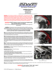
Line Follower
The line follower kit includes a an add-on sensor board, a simple PC application, and
its Visual Basic source code.
Sensor Board Hardware
The board plugs into the expansion port of the robot, so that the 3 infrared sensors
read off the floor just in front of the robot.
The kit is designed for a dark line on a white surface –
• The sensors actually monitor infrared reflectance, but most black and white
surfaces, substances or paints will work.
• The line should be about 2cm or ¾ inch wide.
• Ordinary black electrical insulating tape works well.
The three LEDs on top of the board reflect the state of the sensors: ON over the
background (white), and OFF when detecting the line (dark).
18
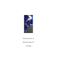
Application
The application “Miabot Line Tracker.exe” presents a single control window :–
Communications
Type your virtual COM port number into the ‘Com port’ box and hit ‘START’.
When the large buttons are ungreyed (enabled), the program is ready to use.
Manual Operation
LEFT, RIGHT, FORWARD and STOP buttons can be used to steer the robot around.
The buttons make the robot move continuously (but fairly slowly), until STOP is
pressed.
Line Following
Pressing ‘FOLLOW’ causes the robot to start line following. The robot begins by
going straight forward for a few seconds, and will try to follow any line it finds.
During line following, the ‘LEFT’, ‘RIGHT’ and ‘FORWARD’ buttons are disabled.
The ‘STOP’ button halts the robot and cancels line following.
Sensors
The ‘sensors’ panel shows the current output of the line-following sensors.
The three buttons L,C and R show the left/centre/right state.
The buttons show off over the background, and on where the line is detected.
19
Tracking Controls
Speed %
This value controls the relative movement speed in line tracking, auto-searching and
in the manual ‘forward’ operation.
It can be controlled 0-100 either via the slider or by typing in the box.
Low settings give more reliable tracking on sharp curves, but speed can often be
increased if the course is fairly smooth.
Turn %
This value 0-100 controls the sharpness of the turn correction that occurs when the
robot runs off the line to one side.
It can be controlled 0-100 either via the slider or by typing in the box.
Low settings will give generally smoother movement, but larger values can follow
sharper bends without losing the line.
N.B. ‘left’ and ‘right’ button turns are not affected –these occur at a fixed rate.
AutoSearch
This option governs what happens when the robot loses the line (includes all-off as
well as all-on state seen by the sensors).
When the line is lost, there is first a short ‘de-glitch’ period during which the robot
runs straight, and then it will either try to find the line again, or stop dead –
• The default is ‘AutoSearch’, where the robot tries to re-find the line by
rotating backward around one wheel to the side it last saw the line.
• If ‘Autosearch’ is turned off, the robot just stops.
AutoSearch generally gives much more robust performance if the line is sometimes
accidentally lost (usually on sharp bends).
The option is also used to control the behaviour at the end of a line: The robot will
either stop or turn around and retrace the line backwards.
20
Robot Firmware Development
Overview
MIABOTs are supplied with standard software already installed.
The ‘c’ source code for the example software is supplied in the files MIABOT.C,
MIABOT.H, EEVARS.H and MAKEFILE. As supplied, these are configured for the
WinAVR development system.
When correctly programmed, the example software will flash the LEDs when the
robot is turned on. It also implements the demo sequence, and most of the standard
commands detailed above.
Compiler Installation
WinAVR is a freeware development environment containing a port of the well-known
GCC compiler. WinAVR is supplied as a self-extracting installer: Run this to install
the software.
Programming
The robot is in-system programmable and new firmware can be downloaded into the
robot via the programming lead.
We supply a freeware development environment called WinAVR. This includes the
GCC ‘c’ compiler for Atmel AVR micros, a full ‘c’ library, a programmer’s editor,
and download and debugging utilities.
At present, we recommend starting with the “PonyProg” programmer instead of the
download tool supplied as part of WinAVR.
PonyProg is a freeware utility supplied by www.lancos.com, which can be used to
take an Intel format hex file (output from GCC) and download it into the robot.
We have supplied the latest version of PonyProg as a zipped file. Please unzip the
setup.exe and run.
21
At this point plug in the programming cable and turn the robot ON.
Now run up PonyProg :–
The first time you use PonyProg, you will need to configure it, selecting the setup
options shown above:
- First select “Interface Setup” from the Setup menu. Select “Parallel” for the
programming port, “LPT1” button for the port (or whichever parallel programming
port you wish to use), and “AVR-ISP I/O” (the hardware interface type) from the
dropdown.
- Next, run “Calibration” from the Setup menu: Follow the instructions to calibrate
PonyProg for the machine speed (N.B. this requires the robot to be connected).
- On the main toolbar, select “AVRMicro” as the processor family and “ATmega8” as
the processor type.
PonyProg should now be set up correctly.
22
To check correct communication with the programmer, you can now read back some
information from the robot: Select “Command\Security and configuration bits”,
which brings up the control pane for the Mega8 fuse and lock-bit settings.
Turn all bits off, then hit the ‘Read’ button to refresh the settings from the robot. It
should look like this :-
The robots are shipped with these Fuse settings already configured. Do not change
anything (or hit “Write”) unless you are quite sure (!).
( N.B. The processor clock controls, CKSEL0..3, are set to 8Mhz which is 1011:
Refer to Atmel datasheet + note that these bits read in reverse logic in PonyProg).
If you are unable to read the fuse settings, some common causes of failure are :–
i)
Cable is not plugged in.
ii)
Robot is not turned on.
iii)
Calibration timing is not correct (run calibration from the setup menu).
iv)
Some PC’s are not always compatible, try downloading an older
version of PonyProg and retry.
Another simple way of verifying the basic connection is to select “Command\Reset”:
The LEDs should flash as the robot reboots.
23
Once communication is established, you can try reprogramming the example
program.
First save a copy of the existing contents:
- Select “Command\Read Program (FLASH)”. The main window should fill up with
code read from the robot.
- Select “File\Save Program (FLASH) File as…”, and save the result as a .hex file,
e.g. “Miabot Original.hex”.
Now, load + program the new file:
- Select “Command\Erase”. This wipes the whole chip. You can confirm that the
light no longer flash when the robot is turned off and on.
- Now select “File\Open Program (FLASH) File …”, and load the example code
“MIABOT.HEX”.
- Select “Command\Write Program (FLASH)”, and PonyProg will reprogram the chip
and verify the data. The robot should work normally again.
Alternative Programming Methods
PonyProg limitations
Current versions of PonyProg have some known problems:
1. For reliable results it may be necessary to always manually erase the device
(Command\Erase) prior to programming: PonyProg has a configurable
automated programming sequence, which can do this for you automatically,
but we have found that using this causes the verify cycle after programming to
fail intermittently.
2. Reading Oscillator Calibration bytes sometimes seems to corrupt the program
window data, leading to bad program data. So always re-load after using these
functions.
3. Fuse settings cannot be saved, verified or programmed from a file.
WinAVR / AvrDude
For more advanced use, we recommend the AvrDude programmer application that
comes with WinAVR.
This is a command-line utility rather than GUI based, but can prove more reliable
than PonyProg and can also solve some PC compatibility problems.
The programming lead provided can be used by selecting the “stk200” parallel
programmer type for AvrDude operations.
For example, the command “avrdude -pm8 -cstk200 -Plpt1” verifies the
programmer connection, reporting either the device signature or an error.
The example code includes a batch file “program_miabot.bat” to program the robot
with avrdude.
See AvrDude documentation for full details.
Atmel AVR Studio
Unfortunately, it is not currently possible to program from AVR Studio via a parallel
lead. Instead you must buy a serially-controlled programmer such as Atmel’s AvrISP.
See Atmel website for details.
24
Writing Robot Programs
You can now modify the example program as you like, or write your own code.
The output from the GCC compiler should be a .HEX file – see GCC documentation
and the example MAKEFILE provided.
NOTE: WinAVR can also interface to Atmel’s “AvrStudio” free development
environment. In particular you can simulate code in AvrStudio by exporting it as a
.ELF file. With suitable hardware you can also use an in-circuit emulator.
A good starting point is to visit the WinAVR homepage at winavr.sourceforge.net.
In the ‘Documentation’ section, you can find the file “install_config_WinAVR.pdf”,
which gives a concise and readable introduction.
25
Appendix A: Miabot board v.5.0A schematic diagram
26
Appendix B: Processor signal connections
(refer to schematic diagram, Appendix A)
Mega8 pin
PD0 (RXD)
PD1 (TXD)
PD2 (INT0)
PD3 (INT1)
PD4 (XCK/T0)
PD5 (T1)
PD6 (AIN0)
PD7 (AIN1)
no.
30
31
32
1
2
9
10
11
signal
RXD
TXD
CNT_RIGHT
CNT_LEFT
PD4_LB
PD5_LF
PD6_RF
PD7_RB
Notes
[expansion port pin]
Serial input to Micro
Serial output from Micro
Opto input Left
Opto input Right
Left REVERSE
Left FORWARD
Right FORWARD
Right REVERSE
PB0 (ICP)
PB1 (OC1A)
PB2 (SS/OC1B)
PB3 (MOSI/OC2)
PB4 (MISO)
PB5 (SCK)
12
13
14
15
16
17
A6/ICP
A7/PWM
SW_~EN
PRG_MOSI
PRG_MISO
PRG_SCK
Interrupt, joined to ADC6
Pwm output, joined to ADC7
enable DIL switches
program in
program out
program clock
PB6
(XTAL1/TOSC1)
PB7
(XTAL2/TOSC2)
7
LED1
330ohm inline resistor
8
LED2
330ohm inline resistor
PC0 (ADC0)
PC1 (ADC1)
PC2 (ADC2)
PC3 (ADC3)
PC4 (ADC4)
PC5 (ADC5)
PC6 (~RESET)
23
24
25
26
27
28
29
A0
A1
A2
A3
A4/SDA
A5/SCL
PRG_RESET
expansion ADC input, digital i/o
expansion ADC input, digital i/o
expansion ADC input, digital i/o
expansion ADC input, digital i/o
expansion ADC input, digital i/o
expansion ADC input, digital i/o
RESET pin, not i/o
ADC6
ADC7
19
22
A6
A7
A/D input, joined to PB0
A/D input, joined to PB1
VCC, VCC2,
AVCC, AREF
4, 6,
18,
20
3, 5,
21
+5V
GND, GND2,
GND3
GND
[3]
[1]
[10]
[8]
[6]
[15]
[13]
[11]
[9]
[7]
[5]
[4]
[3]
[1]
[12]
switched to battery ground
[2]
27
Appendix C: expansion port signals
(refer to schematic diagram, Appendix A)
pin
1
3
5
7
9
11
13
15
2
4
6
8
10
12
14
16
signal
A7/PWM
A6/ICP
A5/SCL
A4/SDA
A3
A2
A1
A0
GND
PRG_RESET
PRG_SCK
PRG_MISO
PRG_MOSI
+5V
V_BAT
-
connects
ADC7, PB1(OC1A)
ADC6, PB0(ICP)
ADC5, PC5
ADC4, PC4
ADC3, PC3
ADC2, PC2
ADC1, PC1
ADC0, PC0
uses
adc, dig-i/o, pwm output
adc, dig-i/o, capture / interrupt input
adc, dig-i/o, I2C-clock
adc, dig-i/o, I2C-data
adc, dig-i/o
adc, dig-i/o
adc, dig-i/o (battery voltage monitoring)
adc, dig-i/o (temperature monitoring)
PC6(RESET)
PB5(SCK)
PB4(MISO)
PB3(MOSI/OC2)
dig i/o, program clock, SPI-clk
dig i/o, program out, SPI-MISO
dig i/o, program in, SPI-MOSI, pwm output
-
unused
28