1
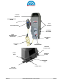
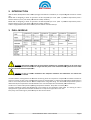
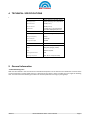
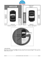
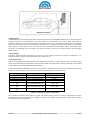
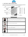
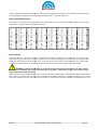
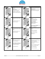
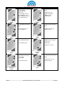
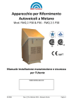
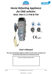
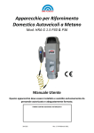
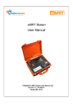
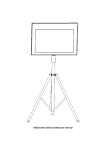
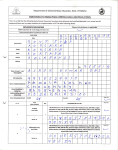
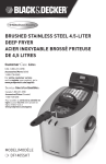
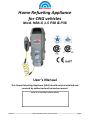
Home Refueling Appliance
for CNG vehicles
Mod. HRA G 1.5 P30 & P36
User’s Manual
This Home Refuelling Appliance (HRA) should only be installed and
serviced by authorized and trained personnel.
STAMP OF AUTHORIZED TECHNICAL SERVICE
39.0152
Rev.4 ENG March 2013 – User’s Manual
Page 1
BRC - FuelMaker - M.T.M. S.r.l. U.
Via Industria, 6 - 12062 - Cherasco - CN - ITALY
International Technical Assistance
Tel. +39.0172.48.68.628 0172.48.68.363 - 0172.48.68.623.- Fax +39.0172.486.630
e-mail: [email protected] - www.brcfuelmaker.it
North America – Canada Technical Assistance
Tel. +1.705.341.19.23
e-mail: [email protected]
39.0152
Rev.4 ENG March 2013 – User’s Manual
Page 2
SUMMARY
1.
SAFETY INSTRUCTIONS ...................................................................................................................................... 4
2.
INTRODUCTION ................................................................................................................................................. 6
3.
PHILL MODELS ................................................................................................................................................... 6
4.
TECHNICAL SPECIFICATIONS .............................................................................................................................. 7
5.
GENERAL INFORMATION ................................................................................................................................... 7
6.
FUNCTIONS OF USER’S CONTROL PANEL ..........................................................................................................10
7.
MAINTENANCE INSTRUCTIONS .........................................................................................................................17
8.
HRA REMOVAL .................................................................................................................................................17
9.
DISPOSAL..........................................................................................................................................................18
10.
WARRANTY CERTIFICATE ..................................................................................................................................19
11.
CE CONFORMITY DECLARATION .......................................................................................................................20
12.
CERTIFICATE SIL 1 .............................................................................................................................................22
TABLES SUMMARY
TABELLA 1 - PHILL MODELS ........................................................................................................................................................ 6
TABELLA 2 - TECHNICAL SPECIFICATION ........................................................................................................................................ 7
TABELLA 3 – COMPENSATION PRESSURE / TEMPERATURE ................................................................................................................ 9
TABELLA 4 -WORKING HOURS CODES ........................................................................................................................................ 11
TABELLA 5 - ERRORS DIAGNOSTICS ............................................................................................................................................ 12
39.0152
Rev.4 ENG March 2013 – User’s Manual
Page 3
1. SAFETY
AFETY INSTRUCTIONS
COMPONENTS
PONENTS ARE NON REPLACEABLE BY USER
USERs SHOULD NOT CARRY OUT ANY MAINTENANCE ON INTERNAL COMPONENTS.
Internal components should only be maintained and overhauled att BRC FuelMaker’s premises or by authorized
dealers.
Do not open or tamper with modules or the warranty
warra
will be invalidated; tampering with or opening
open modules could be
dangerous and cause damage to the compressor and cause serious injury or even death.
READ CAREFULLY BEFORE INSTALLATION
HRAs should only be installed by trained and personnel authorized by BRC FuelMaker.
Please read carefully the manual provided before installation and use.
us
If you have any questions or concerns during installation, please contact your local BRC FuelMaker Distributor.
LOCATION OF Home Refueling Appliance (HRA)
HRAs can be installed both indoors (Garage)
(Ga
and outdoors in safe and protected areas as per installation instructions
and local jurisdictional codes.
The HRA and vehicle have to be located in the same ambient temperature during the refuelling operation to ensure
correct temperature compensation.
See Table
le 2 for temperature compensated maximum fuelling pressures.
pressures
REFUELING APPLIANCE FOR CNG (Compressed Natural Gas) VEHICLES ONLY
Do not use HRA for any other purpose or it may results in serious injury and/or death to and also cause serious
damage to structures. Vehicle gas cylinder should be certified
certified for storing CNG at a 3600 psig or 250 Bar pressure or
higher. HRA is suitable for residential applications, and all installations must comply with installation manuals and
local jurisdictional code requirements.
REFUELING INSTRUCTIONS
Do not refuel with engine turned on and be
b sure that any possible ignition source is absent. Do not smoke or expose
to open flames during refuelling.
IF YOU SMELL GAS
Open allll windows and doors in the location of the HRA if the unit is installed indoors.
indoors
Immediately close the manual valve on natural gas supply line; and, if possible, the valve on the vehicle cylinder.
Switch off any possible ignition sourcess and contact an Authorized Service Centre.
Centre
REFUELING HOSE
The refuelling hose must be protected from damage and abrasion. After refuelling your car, ensure that the refuelling
nozzle is returned to its’ holder. In case of hose and connectorr abrasions or wear, contact your Authorized Technical
Centre for service.
WARNING : DO NOT USE SOLVENT OR AGGRESSIVE CHEMICAL AGENTS FOR CLEANING THE OUTSIDE.
OUTS
USE
ONLY GENTLE DETERGENTS OR SOAP.
39.0152
Rev.4 ENG March 2013 – User’s Manual
Page 4
COOLING
AIR OUTLET
REFUELING NOZZLE
HOLDER
FIXING
BRACKETS
REFUELING NOZZLE
TECHNICAL
DATA LABEL
QUICKDISCONNECTION
BREAKAWAY
REFUELING
HOSE
COOLING AIR
INLET
USER’S
CONTROL PANEL
PRESSURE
RELIEF FITTING
SERIAL
PORT
GAS INLET
FITTING
REFUELING
HOSE
POWER CABLE
EXT. GAS
DETECTOR PORT
39.0152
Rev.4 ENG March 2013 – User’s Manual
Page 5
2. INTRODUCTION
HRA has been developed for both indoors (Garage) and outdoors installation, for compressing
compressing Natural Gas for vehicle
use.
bar
psi at 20° C/68° F (ambient temperature) with a
Model P30 is designed to refuel at a pressure of 207 bar/3,000
3
Nominal Flow of 1,3 sm /h at 50 Hz (1.01 scfm-0.5
scfm
GGE/h at 60 Hz).
Model P36 is designed to refuel at a pressure of 248 bar/3,600
bar
psi at 15° C/59° F (ambient temperature) with a
3
Nominal Flow of 1,3 sm /h at 50 Hz (1.01 scfm-0.5
scfm
GGE/h at 60 Hz).
A HRA is equipped with Internal Gas Sensor/Air Flow Switch and Internal Dryer.
3. PHILL MODELS
Tabella 1 - Phill models
WARNING Phill
hill models without the gas dryer (Smart and Basic) are available but they can be used only if
the gas is already dried. We recommend to use gas with dew point at the maximum delivery pressure of 5°C lower
than the minimum ambient temperature.
WARNING In case of outdoor installation with adequate ventilation the Phill Smart use without the
internal gas detector is allowed
The Phill software is designed for the constant monitoring of the all compressor components The software checks for
pressure increase as well as the maximum filling pressure compensation in reference to the ambient temperature
temper
in
order to avoid overpressures due to external temperature rising after filling. The automatic compensation system is
determined by the temperature sensor installed on the main board (function activated by the manufacturer).
The Phill is air cooled and operates operating temperature between -40°C/-40°F and +45°C/113°F
/113°F.
The Phill ventilation system operates through a fan located in the compressor lower side. The cooling air inlet is
equipped with a grid while the exhaust is located in the compressor
comp
upper side or rear side.
Start, stop, and monitoring are performed by the User Control Panel.
39.0152
Rev.4 ENG March 2013 – User’s Manual
Page 6
4. TECHNICAL SPECIFICATIONS
1.
GAS CIRCUIT
Max Filling Pressure
207 bar (3,000 psig) at 20° C(68°F) ambient
248 bar (3,600 psig) at 15° C (59°F) ambient
Min Inlet Pressure
17 mbar (7” w.c.)
Max Inlet Pressure
35 mbar (14” w.c.)
Nominal Flow
3
1.3 sm /h at 21° C / 15°C - 0.017 bar inlet
1.01 scfm-0.5 GGE/h @ 70°F/59°F-7”w.c.
WIRING CIRCUIT
Electrical Supply
220-240 Volt AC Single Phase, 50/60 Hz
Wiring Circuit Capacity
15 Amp
Full Load Amperes
5.5/5.0 Amp
Average Consumption
0.85 kWh
MECHANICS
Dimensions (L x P x A)
762 x 356 x 330 mm (30”x14”x13”)
Weight
49 Kg/110 lb (packaging included )
Noise
40 dBa at 5 m/16.5 ft.
Covering Protection Level
IP 24
Operating Temperature
From - 40° C to + 46° C (-40°F +115°F)
Tabella 2 - Technical specification
5. General information
- Vehicle Refuelling Point
HRA must be installed in the same location and ambient temperature as the vehicle to be refuelled to ensure that the
correct temperature compensated pressure is delivered to the vehicle; always consider the max length of refuelling
hose and ensure that the refuelling hose does not obstruct pedestrian crossings or passageways.
39.0152
Rev.4 ENG March 2013 – User’s Manual
Page 7
Example for refueling point
Example for refueling point
Max distances
- Impact Protection
HRA should be installed 1,5 mt-5 ft high from the floor so that there will no risk of collision with vehicle. In case of a
bigger vehicle, such as VAN or SUV, additional impact protection may be required (see pict. 5). Local utilities and
codes should be consulted.
39.0152
Rev.4 ENG March 2013 – User’s Manual
Page 8
Protection against Bumps
- Refueling Hose
The HRA refuelling hose must be replaced by authorized personnel trained by BRC-FuelMaker. It can only be replaced
using the correct hose manufactured for use with the HRA to prevent serious injury and or death and damage to
property. A quick disconnect breakaway device is installed in the case of a vehicle driving away when the refuelling
hose is still connected. It parts in two to avoid uprooting HRA from its support, leaving the end of the hose connected
to the vehicle. In the case of a drive away with the hose connected, the hose should only be removed from the
vehicle by an authorized service personnel . Call technical service, do not try to remove fitting to avoid damages
and/or injuries.
- Pressure Relief
A pressure relief line allows discharging of natural gas in the unlikely event that the system overpressures; it is
important keep the pressure relief line free from dirt, material or ice.
- External gas sensor
HRA can be equipped with an External Gas Sensor (Optional) if necessary or required by local code. The External Gas
Sensor is connected to the port situated in the lower side of HRA. Once the sensor installed, it will have to be enabled
in the software by an authorized installation technician.
If ambient temperature detected is lower than - 40° C/-40° F or higher than +45° C/113° F the software will not allow
the HRA to start for safety reasons and an error will be indicated by the User’s Control Panel.
Pressure P30
Pressure P36
Ambient Temperature
207 ± 7bar (3,000± 100 psi)
183 ± 7.5 bar (2,654 ± 108 psi)
166 ± 8.0 bar (2,407 ± 116 psi)
248 ± 7.0 bar (3,600 ± 100 psi)
229 ± 7.5 bar (3,321 ± 108 psi)
211 ± 8.0 bar (3.060 ± 116 psi)
21° / 15° C (70° / 59° F ) or higher
10° C / 50° F
0° C / 32° F
150 ± 8.5 bar (2,175 ± 123 psi)
194 ± 8.5 bar (2,813 ± 123 psi)
- 10° C / 14° F
177 ± 9.0 bar (2.567 ± 130.5 psi)
- 20° C / - -4° F
160 ± 9.5 bar (2,320 ± 137.7 psi)
- 30° C /- -22°F
143 ± 10.0 bar (2,074 ± 145 psi)
- 40° C / - -40° F
133 ± 9.0 bar (1,929 ± 130.5
psi)
116 ± 9.5 bar (1,682 ± 137.7
psi)
100 ± 10.0 bar (1,450 ± 145
psi)
Tabella 3 – Compensation pressure / temperature
User’s should periodically check that the air inlet and exhaust system are free from dirt or obstruction; that the
refuelling hose does not have abrasions, is kinked or have signs of breakage; and that vehicle storage system is tested
and compliant to safety regulations.
39.0152
Rev.4 ENG March 2013 – User’s Manual
Page 9
6. FUNCTIONS OF USER’S CONTROL PANEL
Through the User’s Panel, you can Start or manually Stop the unit. The Panel has a START button and a STOP button,
three LEDs on the left showing State of the unit - Presence of Electrical Supply, Refuelling, Active Regeneration and Error
(Red), and 5 LEDs on the right showing Fuel level indication, Errors or Working Hours (see pict. 16).
(STARTING REFUELING)
F
PRESENCE OF
ELECTRICAL
SUPPLY
97% - 100%
77% - 97%
REFUELING
57% - 77%
37% - 57%
ACTIVE REGENERATION
(in case of dryer)
E
17% - 37%
ANOMALY
FUEL LEVEL INDICATORS
LIGHT
INDICATORS
START
(ERROR)
STOP
User’s Control Panel
(STOP REFUELING)
OPERATING INSTRUCTIONS
1)
With engine off, check the absence of danger, connect Refuelling Nozzle to the vehicle
fuelling receptacle and verify it is correctly connected by pulling it slightly to ensure it will not
disconnect.
2)
Push the START button. The HRA will start working.
3)
If compressor has stopped automatically go to the next step; if you need to stop refuelling
while in progress, press the STOP button.
4)
Disconnect refuelling hose from vehicle and return the refuelling nozzle to the nozzle holder.
39.0152
Rev.4 ENG March 2013 – User’s Manual
Page 10
constantly monitoring and controlling the unit’s operation.
operation Light indicators
A HRA is equipped with diagnostic software constantly
can show different conditions by pushing START and STOP buttons in a specific sequence.
DISPLAY HRA WORKING HOURS
Push STOP to reset panel, then keep START and STOP buttons pressed. Fuel level indicators lights will show unit
working hours. See table below to identify hours code.
Tabella 4 -Working Hours codes
DISPLAY ERRORS
In the case of an error condition, the system stops HRA from working
orking allowing the unit to be reset or locking out the
system depending on the error condition. If the error can be reset,
reset refuelling will restart by first pushing the STOP
button to reset Panel and
d then the START one. In the case of an internal error or gas leak detection, the system will
shut down and lock itself off. An authorized service technician will be required to service and reset the HRA.
WARNING: If software
re blocks HRA, do not disconnect
ct electrical supply as the unit will run when required
exhaust fans and maintain gas sensors until service can be provided.
provided Failure to do so may result in serious injury
and/or death and/or property damage.
When the Error Light is illuminated the User can press and hold the Stop button,
button With the Stop Button depressed the
User’s panel will display the last error code recorded. PC diagnostic software is available to display unit’s
unit current
parameters and Errors Archive. See table below to identify error code and know the possible corrective
correctiv action to carry out.
39.0152
Rev.4 ENG March 2013 – User’s Manual
Page 11
ERROR CODE
CORRECTIVE ACTION
- Check the right inlet
pressure
- Check that inlet manual
valve is open
- Check the adequate
diameter of supply pipe
- Check reducer (if present).
Low Inlet Pressure
ERROR CODE
CORRECTIVE ACTION
- Check that voltage range is
included between 216 V AC
and 252 V AC
- Check HRA right connection
to the electrical supply line
Engine Overvoltage
00001
00101
Disconnect electrical supply
for 1 minute and connect it
again.
- Check possible external
cause:
- Refuelling fitting
- Vehicle equipment
- Refuelling pipe
- Gas Inlet pipe
- Material stored into
refuelling area
If anomaly persists, call
technical support.
High pressure sensor alarm
Int. Gas Sensor Alarm
00010
00110
Disconnect electrical supply
for 1 minute and connect it
again.
- If no causes are found, close
gas manually and call
technical support.
Ambient temperature out of
range:
- Tamb <-45°/-49°F
- Tamb>55°C/131°F
If anomaly persists, call
technical support.
Temperature sensor
malfunction
Overpressure
Ambient temperature out of
range
10111
01110
Back pressure from the car
tank.
Stop the HRA, Re-START
after 5-10 minutes.
Check possible leakages:
- Safety Disconnection device
- Refuelling fitting
- Vehicle equipment and
filling point.
If the problem remains close
the car tank valve and call
the technical support.
This error could occurs if the
car tank is almost empty.
Fill the tank partly.
Do not use the car
Blow down over pressure
Insufficient pressure increasing
00011
00111
Re-START the HRA
Tabella 5 - Errors Diagnostics
39.0152
Rev.4 ENG March 2013 – User’s Manual
Page 12
ERROR CODE
CORRECTIVE ACTION
Check:
- Supply voltage
- Possible air inlets
obstruction
- Air discharge dimension,
min.125mm/4.9”, max.
length 15mt/49ft with max.
3 changes of directiondirection
Fan
ERROR CODE
CORRECTIVE ACTION
Check possible external
cause:
-
Motor overtemperature
High pressure drop
00100
01000
Refuelling fitting
Vehicle equipment
Refuelling pipe
Gas Inlet pipe
Disconnect electrical supply
for 1 minute and connect it
again.
Disconnect electrical supply
for 1 minute and connect it
again.
If anomaly persists, call
technical support.
If anomaly persists, call
technical support.
Bypass-valve malfunction
Combi-valve alarm
11000
10110
Condenser or evaporator or
heater Dryer malfunction.
Dryer condenser
temperature out of range:
< -55°C/
55°C/-67°F
>105°C/221°F
Call technical support.
Call technical support.
Dryer condenser temperature
out of range
Dryer alarm
10000
11001
Dryer evaporator
temperature out of range:
< -55°C/-67°F
67°F
>105°C/221°F
- Disconnect electrical supply
for 1 minute and connect it
again.
If anomaly persists, call
technical support.
Call technical support.
Dryer evaporator temperature
out of range
Peltier power adsorption
11011
11010
Table 5 - Errors Diagnostics (Continue)
39.0152
Rev.4 ENG March 2013 – User’s Manual
Page 13
ERROR CODE
Inadequate Cooling Air Flow
CORRECTIVE ACTION
Check:
- Possible cooling air inlet
obstructions
- Air discharge dimension,
min 125 mm max length 15
mt with max 3 changes of
direction
- Fan
- Ensure operation of air
flow switch checking for
debris blocking movement
01001
ERROR CODE
Ext. Gas Sensor Alarm
01101
- Check possible leakages:
- Refuelling Nozzle
- Vehicle equipment
- Refuelling hose
CORRECTIVE ACTION
- Check possible external
cause:
- Refuelling Nozzle
- Vehicle equipment
- Refuelling Hose
- Gas Inlet pipe
- Material stored into
refuelling area
Eliminate leakage source
(close manual valve) and call
authorized technical support.
Disconnect electrical supply
for 1 minute and connect it
again.
If error condition persists, call
technical support.
Restart HRA.
Max Refueling Time
Electrical error
non-maintainable
01010
11111
Check conformity of gas
supply line pressure to
technical specifications.
Check the pressure regulator
(if present).
High Inlet Pressure
Back-Pressure
01011
Do not disconnect electrical
supply. Do not force refueling
fitting disconnection from
vehicle.
Try to stop and restart HRA
every 5-10 minutes.
If problem persists, close
vehicle manual valve, call
technical support.
Do not use vehicle until error
has been corrected.
22222
Check possible obstructions
or damages:
Check:
- Connections
- Adapter board
- Cables
- Safety Disconnection
device
- Refuelling fitting
- Vehicle filling point
- Refuelling pipe
Try to stop and restart HRA.
If problem persists, replace
user’s control panel.
High Pressure Gas Leakage
01100
Table 5 - Errors Diagnostics (Continue)
39.0152
Start Button Error
10001
Rev.4 ENG March 2013 – User’s Manual
Page 14
ERROR CODE
CORRECTIVE ACTION
Check:
ERROR CODE
- Connections
- Adapter board
- Cables
CORRECTIVE ACTION
- Check possible cooling
system obstruction
- Check the free movement
of flow meter blade
- Check sensor supply voltage
- Replace flow meter
Try to stop and restart HRA.
If problem persists, replace
user’s control panel.
Stop button error
Air flow error
10010
01111
- Check and clean internal
gas sensor
- Check sensor supply voltage
- Replace sensor
- Check connections
- Check sensor supply
voltage
- Replace sensor
Internal gas sensor error
Internal gas sensor calibration
error
10011
10100
Disconnect electrical supply
for 1 minute and connect it
again.
Possible problem related to
excessive jumps of line
voltage.
If anomaly persists, call
technical support.
- If problem is not the line,
Disconnect electrical supply
for 1 minute and connect it
again.
TRIAC error
POWER OFF error
10101
11110
- Possible failure due to the
remote device.
- Possible obstruction of the
tube of high pressure in the
event of a sudden pressure
increase
-Check the connection
- If the problem is not
connecting call for service
Remote communication error
11101
Table 5 - Errors Diagnostics(Continue)
39.0152
-Call technical support.
Sudden pressure increase
11100
Rev.4 ENG March 2013 – User’s Manual
Page 15
- Disconnect electrical
supply for 1 minute and
connect it again
Calibration error
- Disconnect electrical supply
for 1 minute and connect it
again
Software error
Table 5 - Errors Diagnostics(Continue)
Optional functions can be supplied exclusively by the manufacturer:
•
•
•
•
•
•
•
Empty Tank Function
When the tank is completely empty this function allows to make a forced compression to create the necessary conditions
for overcoming the error of Insufficient pressure increasing 00111.
The compressor is placed in standby condition recognizable through the blinking of both filling and error indicators.
To activate this function press three times in three seconds the START button (in case of incorrect procedure the error
High Pressure Gas Leakage 01100 appears.
During the compression the filling indicator remains alight while the error indicator blinks.
At the end of the compression the leak test is performed. If the test is positive the error indicator switch-off and the HRA
continues compressing. If the leak test is not passed the High Pressure Gas Leakage 01100 appears and the HRA stop.
By pressing the STOP button the "Empty tank" function can be stopped and the High Pressure Gas Leakage 01100 error
appears.
During Empty tank (recognizable by the error indicator blinking) supervision is always recommended.
Final pressure compensation function in reference to the ambient temperature. The maximum filling pressure varies
according to the regulations in force in the country of installation. If this function is not required is possible to disable it.
Bypass regeneration function. In case of Dryer error during the regeneration process the HRA stops this function but the
filling goes on. If the by-pass regeneration function is active the Dryer indicator blinks. The bypass regeneration will stop if
one dryer regeneration cycle is completed at least.
Evaporator function (Nafion) Membrane. In case of ambient temperature lower than 5°C/41°F the membrane heater
switch on in order to avoid damages due to ice formation. The heater shutdown if the ambient temperature reaches
7°C/44.6°F.
CMPDrying. This function can be performed by the system before a regeneration in order to purge the moisture
eventually accumulated in the compressor (a number of conditions such as: regeneration required, filling started from
4s, output pressure ≤ 400 psi have to be satisfy). This function is not possible whit HRA models not equipped with
dryer.
Dryer, Internal gas sensor Air Flow Control. These accessories can be avoided if required
Optional functions activated/deactivated by the dealer with the manufacturer permission only:
• External gas detector (provided by manufacturer).
• Maximum filling time.
• Filling pressure increasing check.
• Maximum filling pressure reduction in reference to HRA working hours.
• Time between regenerations.
39.0152
Rev.4 ENG March 2013 – User’s Manual
Page 16
7. MAINTENANCE INSTRUCTIONS
Users and unauthorized personnel should not access internal components for safety reasons; after installation,
authorized personnel should close Cover applying the suitable seal provided with the handbook. HRA should only kept
maintained by authorized personnel suitably
sui
trained.
Technical service should always:
1
2
3
4
Compare errors shown by HRA with table 4
Try to solve problem verifying installation or replacing components
Test HRA to verify if problems have been eliminated
Close and seal HRA
WARNING:
BRC FuelMaker at
a its premises. Any
Any other operation not described in this manual should only be carried out by BRC-FuelMaker
service completed by UNAUTHORIZED personnel will invalidate the warranty and may cause damage to the
compressor, serious injury and/or death.
death
- Ordinary Maintenance Inspection
Periodically check that the outlet pressure is correct (see table 2), verify that refuelling hose does not show abrasions,
cutting or swelling;
welling; always contact an authorized service technician if damage to the hose is noted.
noted Always check
refuelling nozzle and the quick-disconnect
disconnect breakaway device, contact an authorized service technician if damage is
noted. Check that pressure relief and front/rear air inlets are free from material or ice.
Any attempt
ttempt to tamper with or open modules can cause damage, serious injury and/or death , and invalidate the
warranty.
8. HRA REMOVAL
If you need to remove the unit, follow these instructions:
•
•
•
•
Check that Electric Supply button is OFF and gas inlet valve closed.
Check the absence of voltage on electric supply cable and disconnect it.
Disconnect Inlet and Discharge pipe from HRA verifying the absence of overpressures; close fittings.
Pack HRA with its original packaging.
For further information, please feell free to contact Technical Service.
39.0152
Rev.4 ENG March 2013 – User’s Manual
Page 17
9. DISPOSAL
RIGHT DISPOSAL
At the end of the HRA’s life, it should be removed and disposed according to installation
Country laws in force.
A suitable separate collection for the following recycle and environmental disposal helps to
avoid possible negative effects on environment and health and favours re-use
re
and/or
recycle of HRA materials.
DO NOT DISPOSE COMPRESSOR TOGETHER WITH DOMESTIC WASTE
PHILL CONTAINS MATERIAL ABSORBING MERCAPTAN FROM NATURAL
GAS DURING REFUELING OPERATIONS
----------------------------------------------------------------------------------------------------------------------------------------------------------------------------------------------------------------------------------Waste from Electrical and Electronic Equipment
(WEEE)
(Valid for European Union and other European
Countries with waste separate collection systems)
This symbol
on HRA, or on its documents means
that product should be disposed at the end of its life
according to directive 2002/96/CE about waste from
Electrical and Electronic Equipment (WEEE) and
implementation in national law.
HRA should not be disposed as urban waste but rather be delivered to the suitable
collection point for electrical and electronic equipment.
equipment
Phill contains material absorbing mercaptan from natural gas durint refueling operations.
In case of wrong HRA disposal, you will be responsible for it in accordance with laws in
force.
For further information about disposal and recycle of HRA please contact authorised
offices or call your local BRC FuelMaker Distributor
39.0152
Rev.4 ENG March 2013 – User’s Manual
Page 18
10. WARRANTY CERTIFICATE
WARRANTY CONDITIONS
M.T.M. Srl guarantees products for 24 months starting from the date of purchasing, within the limit of
2,000 working hours.
Purchasing should be proved by a fiscally valid receipt issued by the seller (fiscal ticket, invoice or
transportation bill) identifying the product, the date of purchasing and/or delivery.
During the whole warranty period M.T.M. Srl engages itself to:
(a) restore faulty products assuming all burdens of expenses concerning spare parts and
transportation
(b) replace faulty products not usefully repairable (e.g. when repair will cost more than replacement).
GENERAL CONDITIONS
In order to benefit from warranty, the user will contact the seller and/or installer that will repair the
machine having ascertained the working defect.
If seller and/or installer cannot solve the problem, the machine will be forwarded to BRC FuelMaker
that will repair it or replace it with a new one at its own discretion.
The machine will be returned to BRC FuelMaker in its original packaging; lack of this packaging will
automatically cause the warranty forfeiture.
Warranty will be acknowledged only if the purchasing receipt will be sent by fax or mail at the
moment of the intervention request:
BRC FuelMaker – Warranty Dept.
Fax: +39 0172.486.630
E.mail: [email protected]
This warranty will not cover:
a)
b)
c)
d)
Fair wear and tear
Damages deliberately caused or due to negligence
Damages caused by inobservance of working instruction or by a wrong installation
Damages on non-functioning components that do not jeopardize the regular machine work,
scratches and difference in colours included
e) Accidental damages caused by foreign body or substance, especially included the non-standard
composition of the gas supplied to the machine (gas quality).
f) Repairs carried out by unauthorized assistance centres or repairs realized with non original spare
parts
g) Damages caused by transportation
39.0152
Rev.4 ENG March 2013 – User’s Manual
Page 19
11. CE CONFORMITY DECLARATION
39.0152
Rev.4 ENG March 2013 – User’s Manual
Page 20
39.0152
Rev.4 ENG March 2013 – User’s Manual
Page 21
12. CERTIFICATE SIL 1
39.0152
Rev.4 ENG March 2013 – User’s Manual
Page 22