1
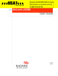
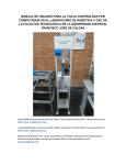
USER MANUAL LS300G-EU GSM/GPRS/EDGE/HSPA+ Sierra Wireless Cellular Modem Issued: 23.11.15 Copyright © 2014-2015 Campbell Scientific Inc. Printed under licence by Campbell Scientific Ltd. CSL 1082 Guarantee This equipment is guaranteed against defects in materials and workmanship. We will repair or replace products which prove to be defective during the guarantee period as detailed on your invoice, provided they are returned to us prepaid. The guarantee will not apply to: Equipment which has been modified or altered in any way without the written permission of Campbell Scientific Batteries Any product which has been subjected to misuse, neglect, acts of God or damage in transit. Campbell Scientific will return guaranteed equipment by surface carrier prepaid. Campbell Scientific will not reimburse the claimant for costs incurred in removing and/or reinstalling equipment. This guarantee and the Company’s obligation thereunder is in lieu of all other guarantees, expressed or implied, including those of suitability and fitness for a particular purpose. Campbell Scientific is not liable for consequential damage. Please inform us before returning equipment and obtain a Repair Reference Number whether the repair is under guarantee or not. Please state the faults as clearly as possible, and if the product is out of the guarantee period it should be accompanied by a purchase order. Quotations for repairs can be given on request. It is the policy of Campbell Scientific to protect the health of its employees and provide a safe working environment, in support of this policy a “Declaration of Hazardous Material and Decontamination” form will be issued for completion. When returning equipment, the Repair Reference Number must be clearly marked on the outside of the package. Complete the “Declaration of Hazardous Material and Decontamination” form and ensure a completed copy is returned with your goods. Please note your Repair may not be processed if you do not include a copy of this form and Campbell Scientific Ltd reserves the right to return goods at the customers’ expense. Note that goods sent air freight are subject to Customs clearance fees which Campbell Scientific will charge to customers. In many cases, these charges are greater than the cost of the repair. Campbell Scientific Ltd, 80 Hathern Road, Shepshed, Loughborough, LE12 9GX, UK Tel: +44 (0) 1509 601141 Fax: +44 (0) 1509 601091 Email: [email protected] www.campbellsci.co.uk PLEASE READ FIRST About this manual Please note that this manual was originally produced by Campbell Scientific Inc. primarily for the North American market. Some spellings, weights and measures may reflect this origin. Some useful conversion factors: Area: 1 in2 (square inch) = 645 mm2 Length: Mass: 1 in. (inch) = 25.4 mm 1 ft (foot) = 304.8 mm 1 yard = 0.914 m 1 mile = 1.609 km 1 lb (pound weight) = 0.454 kg Pressure: 1 psi (lb/in2) = 68.95 mb Volume: 1 UK pint = 568.3 ml 1 UK gallon = 4.546 litres 1 US gallon = 3.785 litres 1 oz. (ounce) = 28.35 g In addition, while most of the information in the manual is correct for all countries, certain information is specific to the North American market and so may not be applicable to European users. Differences include the U.S standard external power supply details where some information (for example the AC transformer input voltage) will not be applicable for British/European use. Please note, however, that when a power supply adapter is ordered it will be suitable for use in your country. Reference to some radio transmitters, digital cell phones and aerials may also not be applicable according to your locality. Some brackets, shields and enclosure options, including wiring, are not sold as standard items in the European market; in some cases alternatives are offered. Details of the alternatives will be covered in separate manuals. Part numbers prefixed with a “#” symbol are special order parts for use with non-EU variants or for special installations. Please quote the full part number with the # when ordering. Recycling information At the end of this product’s life it should not be put in commercial or domestic refuse but sent for recycling. Any batteries contained within the product or used during the products life should be removed from the product and also be sent to an appropriate recycling facility. Campbell Scientific Ltd can advise on the recycling of the equipment and in some cases arrange collection and the correct disposal of it, although charges may apply for some items or territories. For further advice or support, please contact Campbell Scientific Ltd, or your local agent. Campbell Scientific Ltd, 80 Hathern Road, Shepshed, Loughborough, LE12 9GX, UK Tel: +44 (0) 1509 601141 Fax: +44 (0) 1509 601091 Email: [email protected] www.campbellsci.co.uk Precautions DANGER — MANY HAZARDS ARE ASSOCIATED WITH INSTALLING, USING, MAINTAINING, AND WORKING ON OR AROUND TRIPODS, TOWERS, AND ANY ATTACHMENTS TO TRIPODS AND TOWERS SUCH AS SENSORS, CROSSARMS, ENCLOSURES, ANTENNAS, ETC. FAILURE TO PROPERLY AND COMPLETELY ASSEMBLE, INSTALL, OPERATE, USE, AND MAINTAIN TRIPODS, TOWERS, AND ATTACHMENTS, AND FAILURE TO HEED WARNINGS, INCREASES THE RISK OF DEATH, ACCIDENT, SERIOUS INJURY, PROPERTY DAMAGE, AND PRODUCT FAILURE. TAKE ALL REASONABLE PRECAUTIONS TO AVOID THESE HAZARDS. CHECK WITH YOUR ORGANIZATION'S SAFETY COORDINATOR (OR POLICY) FOR PROCEDURES AND REQUIRED PROTECTIVE EQUIPMENT PRIOR TO PERFORMING ANY WORK. Use tripods, towers, and attachments to tripods and towers only for purposes for which they are designed. Do not exceed design limits. Be familiar and comply with all instructions provided in product manuals. Manuals are available at www.campbellsci.eu or by telephoning +44(0) 1509 828 888 (UK). You are responsible for conformance with governing codes and regulations, including safety regulations, and the integrity and location of structures or land to which towers, tripods, and any attachments are attached. Installation sites should be evaluated and approved by a qualified engineer. If questions or concerns arise regarding installation, use, or maintenance of tripods, towers, attachments, or electrical connections, consult with a licensed and qualified engineer or electrician. General • Prior to performing site or installation work, obtain required approvals and permits. Comply with all governing structure-height regulations, such as those of the FAA in the USA. • Use only qualified personnel for installation, use, and maintenance of tripods and towers, and any attachments to tripods and towers. The use of licensed and qualified contractors is highly recommended. • Read all applicable instructions carefully and understand procedures thoroughly before beginning work. • Wear a hardhat and eye protection, and take other appropriate safety precautions while working on or around tripods and towers. • Do not climb tripods or towers at any time, and prohibit climbing by other persons. Take reasonable precautions to secure tripod and tower sites from trespassers. • Use only manufacturer recommended parts, materials, and tools. Utility and Electrical • You can be killed or sustain serious bodily injury if the tripod, tower, or attachments you are installing, constructing, using, or maintaining, or a tool, stake, or anchor, come in contact with overhead or underground utility lines. • Maintain a distance of at least one-and-one-half times structure height, or 20 feet, or the distance required by applicable law, whichever is greater, between overhead utility lines and the structure (tripod, tower, attachments, or tools). • Prior to performing site or installation work, inform all utility companies and have all underground utilities marked. • Comply with all electrical codes. Electrical equipment and related grounding devices should be installed by a licensed and qualified electrician. Elevated Work and Weather • Exercise extreme caution when performing elevated work. • Use appropriate equipment and safety practices. • During installation and maintenance, keep tower and tripod sites clear of un-trained or non-essential personnel. Take precautions to prevent elevated tools and objects from dropping. • Do not perform any work in inclement weather, including wind, rain, snow, lightning, etc. Maintenance • Periodically (at least yearly) check for wear and damage, including corrosion, stress cracks, frayed cables, loose cable clamps, cable tightness, etc. and take necessary corrective actions. • Periodically (at least yearly) check electrical ground connections. WHILE EVERY ATTEMPT IS MADE TO EMBODY THE HIGHEST DEGREE OF SAFETY IN ALL CAMPBELL SCIENTIFIC PRODUCTS, THE CUSTOMER ASSUMES ALL RISK FROM ANY INJURY RESULTING FROM IMPROPER INSTALLATION, USE, OR MAINTENANCE OF TRIPODS, TOWERS, OR ATTACHMENTS TO TRIPODS AND TOWERS SUCH AS SENSORS, CROSSARMS, ENCLOSURES, ANTENNAS, ETC. Contents PDF viewers: These page numbers refer to the printed version of this document. Use the PDF reader bookmarks tab for links to specific sections. 1. Introduction ................................................................ 1 2. Cautionary Statements .............................................. 1 3. Initial Inspection ........................................................ 1 3.1 Ships With List .................................................................................... 1 4. Quickstart ................................................................... 2 4.1 4.2 4.3 4.4 4.5 4.6 Establish Cellular Service .................................................................... 2 Install the SIM Card ............................................................................. 2 Configure LS300G-EU ........................................................................ 3 Set up LoggerNet ................................................................................. 5 Set Up Hardware .................................................................................. 7 Test the Connection ............................................................................. 7 5. Overview ..................................................................... 8 6. Specifications ............................................................ 8 6.1 LS300G-EU Specifications .................................................................. 8 7. Installation .................................................................. 9 7.1 7.2 7.3 Base Station Requirements for LS300G-EU ........................................ 9 Datalogger Site Equipment .................................................................. 9 Wiring and Connections ..................................................................... 10 7.3.1 Modem Connection to the RS-232 Port ...................................... 10 7.3.2 Modem Connections to CS I/O Port Using the SC105 ............... 11 7.3.3 Modem Connection to the CS I/O Port Using the SC932A ........ 13 7.3.4 Antenna Connection.................................................................... 13 7.4 Power Considerations ........................................................................ 14 7.5 AceManager and Template Files ....................................................... 14 7.6 Enabling PPP Mode ........................................................................... 17 8. Operation .................................................................. 19 8.1 8.2 8.3 Ports ................................................................................................... 19 LED Indicator Lights ......................................................................... 19 Reset Button ....................................................................................... 20 9. Troubleshooting ...................................................... 20 i Appendices A. Controlling Power to the LS300G-EU ................... A-1 B. EmailSend Using the Gmail Outgoing SMTP Server ................................................................... B-1 B.1 B.2 B.3 B.4 Setting up a Gmail Account ............................................................. B-1 Sending to Multiple Addresses ........................................................ B-1 Sending a Text Message to a Phone ................................................. B-2 EmailSend Program Example .......................................................... B-2 C. Configuring the LS300G-EU for Dynamic IP ........ C-1 D. Using the LS300G-EU Ethernet Port ..................... D-1 E. LS300G-EU Settings .............................................. E-1 E.1 E.2 E.3 Modem Status Tab ........................................................................... E-1 Settings Tab ..................................................................................... E-2 Dynamic DNS Tab ........................................................................... E-2 F. Regulatory Information .......................................... F-1 F.1 F.2 F.3 F.4 F.5 F.6 Important Information for North American Users ........................... F-1 RF Exposure .................................................................................... F-1 EU .................................................................................................... F-2 Declaration of Conformity ................................................................ F-2 WEEE Notice ................................................................................... F-2 RoHS Compliance ........................................................................... F-3 4-1. 7-1. 7-2. 7-3. 7-4. 7-5. 9-1. 9-2. 9-3. C-1. SIM card installation ............................................................................ 2 9528 Antenna for use with the LS300G-EU modem ......................... 10 Connections using pn #18663 Null Modem Cable ............................ 11 Connections using the SC105 ............................................................ 12 Connections using the SC932A ......................................................... 13 Antenna Connection........................................................................... 13 Can’t Connect… ................................................................................ 21 Can’t Connect, Network Light is Green…......................................... 22 One computer can connect, other(s) cannot… ................................... 23 Serial Server Mode with Dynamic IP .............................................. C-3 Figures ii LS300G-EU GSM/GPRS/EDGE/HSPA+ Sierra Wireless Cellular Modem 1. Introduction This manual provides information for interfacing the Sierra Wireless LS300G-EU cellular modem to Campbell Scientific dataloggers. The LS300G-EU digital cellular modem is manufactured by Sierra Wireless for use on GSM (Global System for Mobile Communications) networks. The modem is accessed through the Internet using TCP/IP communications protocol. Use of the LS300G-EU requires an AT&T® GSM/GPRS/EDGE/HSPA+ business account or an equivalent account from another service provider. See Section 4.1, Establish Cellular Service (p. 2), for more information. For additional information on the LS300G-EU modem, see the Support section of the Sierra Wireless website. Before using the LS300G-EU, please study 2. 3. Section 2, Cautionary Statements (p. 1) Section 3, Initial Inspection (p. 1) Section 4, Quickstart (p. 2) Cautionary Statements READ AND UNDERSTAND the Precautions section at the front of this manual. CAUTION: This device uses considerably more power than cellular modems previously offered by Campbell Scientific (see Section 6, Specifications (p. 8)) and will require a larger power supply, switching power with the datalogger, or a combination of these to ensure the battery is not drained. See Appendix A, Controlling Power to the LS300G-EU (p. A-1), for program examples of using switched 12V to control power to the LS300G-EU. Initial Inspection 3.1 Upon receipt of the LS300G-EU, inspect the package and contents for damage. File any damage claims with the shipping company. Immediately check package contents against the shipping documentation (see Section 3.1, Ships With List (p. 1)). Contact Campbell Scientific about any discrepancies. Ships With List (1) grey power cable (1) Resource DVD 1 LS300G-EU GSM/GPRS/EDGE/HSPA+ Sierra Wireless Cellular Modem 4. Quickstart 4.1 Establish Cellular Service What you need: GSM/GPRS/EDGE/HSPA+ account established with your local carrier. An Access Point Name (APN) must be associated with the account to make the modem accessible through the Internet. The user must program the APN name into the modem as described in Section 4.3, Configure LS300G-EU (p. 3). Your carrier will provide a Subscriber Identity Module (SIM) card for each modem. The SIM card must be installed inside of the modem as described in Section 4.2, Install the SIM Card (p. 2). In addition to the SIM card, you should receive: 4.2 10-digit MSISDN number (telephone number associated with the SIM, used for billing) IP Address and APN for GSM/GPRS/EDGE/HSPA+ service Install the SIM Card The SIM in the LS300G-EU is a smartcard that securely stores the key identifying a mobile subscriber. You will only need to install the SIM once in the life of the modem. To install the SIM card: 1. Remove the SIM card cover. 2. When viewed from the top, the notched corner of the SIM card faces towards the centre of the device as shown in Figure 4-1. Gently slide the card into the slot in the connector until it stops. 3. Replace the SIM card cover. Figure 4-1. SIM card installation 2 User Manual 4.3 Configure LS300G-EU NOTE Quickstart describes configuring the LS300G-EU in serial server mode. It may also be configured in Point-to-Point Protocol (PPP) mode. For a description of the modes, see Section 5, Overview (p. 8). For instructions on setting up the LS300G-EU in PPP mode, see Section 7.5, AceManager and Template Files (p. 14), and Section 7.6, Enabling PPP Mode (p. 17). The LS300G-EU setup for serial server mode may be done with the Device Configuration Utility (DevConfig) version 2.09 or later. DevConfig may be updated/downloaded at no charge at www.campbellsci.com/downloads. (The LS300G-EU can also be set up in serial server mode using template files. See Section 7.5, AceManager and Template Files (p. 14).) Connect a serial cable (for example, USB-to-serial, between the PC and the 9-pin serial port on the LS300G-EU. Open DevConfig (either from the PC’s Start menu or by clicking the icon within LoggerNet) and select LS300 from the Cellular Modem group in the left panel. In the lower left, select the correct Communication Port. Select the Baud Rate. If unsure of the baud rate, click Find Baud Rate. For a new LS300G-EU, 115200 is the correct baud rate. Click Connect. Click Load CSI Settings at the bottom of the screen. On the Modem Status tab, note that the Modem Phone Number and Modem IP Address are displayed, once the modem has authenticated on the network. 3 LS300G-EU GSM/GPRS/EDGE/HSPA+ Sierra Wireless Cellular Modem On the Settings tab: Set the RS-232 Baud Rate appropriate to the datalogger being used: o 115.2K for CR800 Series, CR1000, CR3000, and CR6 Series o 9600 for all others Enter I2GOLD (or your custom APN) in the APN field. Note that the default Device Port number is 3001. This is used in the LoggerNet setup below. Click Apply to save the settings. Reset the modem by briefly pressing the Reset button on the front of the modem or by removing power from the modem. 4 User Manual 4.4 Set up LoggerNet The LoggerNet Network Map is configured from the LoggerNet Setup screen. NOTE Setup has two options, EZ (simplified) and Standard. Click on the View menu at the top of the Setup screen, and select Standard view. From the LoggerNet toolbar, click Main | Setup and configure the Network Map as described below. 1. Select Add Root | IPPort. 2. Add a datalogger to the IPPort (PakBus® dataloggers, for example the CR1000, require a PakBusPort). 3. Select the IPPort in the Network Map. Enter the LS300G-EU IP address (or domain name) and port number. The IP address and port number are input in the Internet IP Address field separated by a colon. Preceding zeros are not entered in the Internet IP Address (for example, 070.218.074.247 is entered as 70.218.74.247). DevConfig and the LS300G-EU template file configure the port number to 3001 for serial server mode. Set the Extra Response Time to 4 seconds. 5 LS300G-EU GSM/GPRS/EDGE/HSPA+ Sierra Wireless Cellular Modem Example settings for a static IP address: 4. 6 For PakBus® dataloggers, leave the default settings for the PakBusPort. PakBus Port Always Open should not be checked. User Manual 5. 4.5 For PakBus® dataloggers, set the PakBus Address to match that of the datalogger (default address in the datalogger is 1). Click Apply to save the changes. Set Up Hardware The simplest hardware setup for modern dataloggers is to connect a null modem cable (CSI pn #18663) between the RS-232 ports of the datalogger and the LS300G-EU. See Section 7.3, Wiring and Connections (p. 10). 4.6 Test the Connection After the Network Map has been configured, test the cellular connection using the Connect screen as shown below. Click on the appropriate station and click Connect to initiate a call to the datalogger. If the call is successful, the connectors at the bottom of the screen will come together and clock information from the datalogger will be displayed in the Station Date/Time field. If the connection fails, a Communications Failure message will be displayed. Troubleshooting procedures can be found in Section 9, Troubleshooting (p. 20). 7 LS300G-EU GSM/GPRS/EDGE/HSPA+ Sierra Wireless Cellular Modem 5. Overview The LS300G-EU modem may be configured in one of two ways, depending on the communications type and needs of the user. For many applications that just need a connection for data collection and datalogger maintenance or monitoring, setup as a serial server is sufficient. In this mode, the modem receives IP communications over the cellular network and converts those to serial (RS-232) communications to pass on to the datalogger. From the datalogger’s perspective, this is no different than a serial cable connecting it to a PC. Section 4, Quickstart (p. 2), describes setting up the LS300G-EU in serial server mode. Alternatively, if IP communications are needed on the datalogger, the modem may be set up in Point-to-Point Protocol (PPP) mode. In this mode, the modem simply passes IP communications directly to the datalogger. This enables features such as FTP, HTTP, and emailing. For information on configuring the LS300G-EU in PPP mode, see Section 7.5, AceManager and Template Files (p. 14), and Section 7.6, Enabling PPP Mode (p. 17). See Appendix B, EmailSend Using the Gmail Outgoing SMTP Server (p. B-1), for more information on emailing. 6. Specifications 6.1 LS300G-EU Specifications Sierra Wireless AirLink® LS300 cellular modem (SL8092 radio module) Network: 3G HSPA+ with fallback to GSM/GPRS/EDGE Host Interfaces 10/100 Base-T RJ45 Ethernet RS-232 serial port, DB9 female USB version 2.0 with micro-B connector 2 SMA antenna connectors (primary, GPS/diversity) Active antenna support Power Input Voltage: 7 to 28 Vdc Current Consumption (@12 Vdc) o Dormant (idle for 10 to 20 s): 185 mA o Transmit/Receive: 255 mA Frequency GSM/GPRS/EDGE: 900/850/900/1800 MHz HSPA+[WCDMA]: 900/2100 MHz (European version) If WCDMA operation at 900/2100 MHz is required, an alternate radio module (SL8092) is available. Dimensions: 76 mm x 90 mm x 25 mm (3.0 in x 3.5 in x 1.0 in) Weight: 190 g (6.7 oz) Size 8 User Manual Environmental Operating Temperature Range: –30 to 70 °C (–22 to 158 °F) Storage Temperature: –40 to 85 °C (–40 to 185 °F) Humidity: 90% @ 60 °C Military Specification : MIL-STD-810 conformance to thermal, mechanical shock, and humidity Industry Certifications 7. PRCRN, R&TTE, FCC, Industry Canada, CE, RoHS Compliant, Class 1 Div 2 Installation 7.1 Base Station Requirements for LS300G-EU PC running Campbell Scientific’s LoggerNet or PC400 software with access to the Internet. 7.2 Datalogger Site Equipment LS300G-EU modem with power cable (included with modem). Datalogger — 21X, CR510, CR10(X), CR23X, CR7, CR2XX, CR1000, CR5000, CR3000, CR800 Series, CR6 Series. Modem Interface If connecting to RS-232 port: Null Modem Cable (pn #18663) — connects the modem to the CR23X, CR3000, CR800, CR2XX, CR1000, or CR5000 RS-232 port. If connecting to CS I/O port: SC105 or SC932A Interface — connects the modem to the 21X, CR510, CR10(X), CR7, or any current datalogger with a CS I/O port. The SC105 must be configured for use with the modem using DevConfig. Settings should be: CS I/O Mode: SDC Address 7, 8, 10, or 11 RS-232 Mode: Modem Baud Rate: 115.2K or 9600 baud depending on datalogger model 8 data bits, 1 stop bit, no parity LS300 Mounting Kit (pn #30988) — includes mounting hardware for securing the modem to below-referenced environmental enclosure and a 9-pin male to 9-pin female cable. Antenna — various antennas are available from Campbell Scientific. Contact a Campbell Scientific application engineer for help in determining the best antenna for your application. 9 LS300G-EU GSM/GPRS/EDGE/HSPA+ Sierra Wireless Cellular Modem Figure 7-1. 9528 antenna for use with the LS300G-EU modem (other antennae are available) 7.3 Power Supply (see Section 7.4, Power Considerations (p. 14)). Environmental Enclosure — ENC10/12, ENC12/14, or ENC16/18. Wiring and Connections 7.3.1 Modem Connection to the RS-232 Port Part number #18663 Null Modem Cable is used to connect the modem to the CR23X, CR3000, CR800, CR2XX, CR1000 or CR5000 RS-232 port (not compatible with the 21X, CR510, CR10X, or CR7 dataloggers). Part number #31055 RS-232/CPI RJ45 to DB9 Male DTE is used to connect the modem to the CR6. 10 User Manual Wiring: Red 12V (or switched 12V) Black G White Same as Red Green No connection Figure 7-2. Connections using pn #18663 Null Modem Cable 7.3.2 Modem Connections to CS I/O Port Using the SC105 The SC105 interface is used to connect the modem to a datalogger CS I/O port, and is recommended for dataloggers with the PakBus® operating system. The SC105 can be connected directly to the modem RS-232 port. Alternatively, it can be connected to the modem using the serial cable supplied with the SC105 (pn #10873). 11 LS300G-EU GSM/GPRS/EDGE/HSPA+ Sierra Wireless Cellular Modem Wiring: Red 12V (or switched 12V) Black G White Same as Red Green No connection Figure 7-3. Connections using the SC105 SC105 Settings: CS I/O Mode: SDC Address 7, 8, 10, or 11 RS-232 Mode: Modem Baud Rate: 115.2K or 9600 baud depending on datalogger model 8 data bits, 1 stop bit, no parity 12 User Manual 7.3.3 Modem Connection to the CS I/O Port Using the SC932A The SC932A interface is used to connect the modem to the CS I/O port, and is recommended for dataloggers with the mixed-array operating system (for example, the CR10X). The SC932A can be connected directly to the modem RS-232 port. Alternatively, it can be connected to the modem using the serial cable supplied with the SC932A (pn #10873). Wiring: Red 12V (or switched 12V) Black G White Same as Red Green No connection Figure 7-4. Connections using the SC932A 7.3.4 Antenna Connection Connect the antenna to the SMA antenna connector as indicated below. Figure 7-5. Antenna Connection 13 LS300G-EU GSM/GPRS/EDGE/HSPA+ Sierra Wireless Cellular Modem 7.4 Power Considerations CAUTION The LS300G-EU uses considerably more power than cellular modems previously offered by Campbell Scientific, Inc. and will require a larger power supply, switching power with the datalogger, or a combination of these to ensure the battery is not drained. A power cable included with the modem connects to the datalogger 12V or switched 12V terminal. Connection to the switched 12V terminal allows the datalogger to switch power to the modem during scheduled transmission intervals if desired. See Appendix A, Controlling Power to the LS300G-EU (p. A-1), for switched 12V program examples. Connect the red and white lead wires to 12V for constant power and to SW12 for program-controlled power, and the black lead to G (ground). The green wire lead is not necessary and can be removed or insulated. When using the switched 12V terminal, the modem can typically be powered with a BP12 battery, CH150 charger/regulator, and SP10 solar panel. 7.5 AceManager and Template Files Section 4, Quickstart (p. 2), describes how to set up the LS300G-EU in serial server mode using DevConfig. AceManager along with template files can be used to set up the LS300G-EU in serial server mode or PPP. AceManager is accessed via a web browser. For initial setup or troubleshooting with a direct (cabled) connection, connect a standard Ethernet (RJ45) cable between the Ethernet port on the PC and that on the modem. Type http://192.168.13.31:9191 into a web browser. Once the modem is provisioned on the network, it may be accessed over the air by typing http:// followed by the IP address (dynamic or static) of the modem, followed by the port :9191. The first screen is a login (shown below). The default password is 12345 and it is strongly recommended to leave it as the default. If security is of concern, contact a Campbell Scientific application engineer to discuss options. 14 User Manual After entering the password and pressing enter (or clicking Log In), the following status screen is displayed. Template files from Campbell Scientific’s website (www.campbellsci.com/downloads) are used to configure the LS300G-EU modem using AceManager. Template files for the LS300G-EU Description LS300G Template 115200 Serial server mode or PPP mode, for newer dataloggers* LS300G Template 9600 Serial server mode, for older dataloggers** that support 9600 baud * CR1000, CR800, CR3000, CR6 Series ** CR200(X), CR10(X), CR510, CR500, 21X, and CR7 15 LS300G-EU GSM/GPRS/EDGE/HSPA+ Sierra Wireless Cellular Modem Click the Template link in the top right of the screen. When prompted for a template file name, select LS300G-EU Template 115200 or LS300G-EU Template 9600. The following screen shows the settings under the Serial tab after the 115200 baud template file has been loaded. Under Advanced, change AT Verbose Mode to Numeric for use with CR10(X), CR510, and CR23X dataloggers. 16 User Manual Click on WAN/Cellular for the following screen: Enter the APN as shown in the screen above. The example is for an APN = I2GOLD. After the template file has been loaded, and the APN entered, click Apply to save the changes in the modem. Click Reboot to restart the modem. Alternately, reset the modem by pressing Reset on the front of the modem or by removing power from the modem. Click Logout to terminate communications with the modem. WARNING Unless you Apply the commands, the changes made will not be saved in the modem. For most commands, you must reboot the modem for the newly written values to take effect. The modem is now set up in serial server mode. To enable PPP mode, see Section 7.6, Enabling PPP Mode (p. 17). 7.6 Enabling PPP Mode The first step in enabling PPP mode is using the template file to configure the LS300G-EU as described in Section 7.5, AceManager and Template Files (p. 14). After configuring the modem, you must use DevConfig to configure the datalogger for PPP mode. Connect to your datalogger in DevConfig and go to the PPP tab. 17 LS300G-EU GSM/GPRS/EDGE/HSPA+ Sierra Wireless Cellular Modem For the Config/Port Used, use the drop-down list to select the datalogger port you wish to use for PPP. RS-232 is the standard choice, but any port in the drop-down list can be used. Set the Modem Dial String to AT\APPP. Press Apply to apply the changes. With PPP enabled, PakBus/TCP communications use port 6785. Therefore, in LoggerNet use :6785 after the IP address or domain name as shown below. 18 User Manual 8. Operation 8.1 Ports RS-232 The RS-232 port is the main port used with Campbell Scientific dataloggers. Its function is described throughout this manual. USB The USB Port is not used in Campbell Scientific applications. Ethernet The Ethernet port may be used in place of PPP Mode to get to the IP stack of the datalogger. However, this method comes with higher current drain for both the modem and the datalogger. See Appendix D, Using the LS300G-EU Ethernet Port (p. D-1), for more information. 8.2 LED Indicator Lights When your LS300G-EU is connected to power and an antenna, there is a specific pattern to the lights to indicate its operation mode. LED Colour Coding: Off – No activity Red – No functionality Yellow – Limited functionality Green – Full functionality Blinking – Altered or reduced functionality Network LED – monitors the cellular network Red – no cellular coverage Flashing red – attempting to connect to cellular network Yellow – cellular network found, modem connecting Flashing yellow – unable to authenticate on the network Green – connected to cellular network Flashing green – roaming Signal LED – shows the strength of the cellular signal Flashing red – no signal (RSSI worse than –110 dBm) Red – poor signal (RSSI between –100 and –110 dBm) Yellow – marginal signal (RSSI between –85 and –100 dBm) Green – good signal (RSSI better than –85 dBm) Activity LED – indicates whether data are currently being transferred Off – normal Flashing green – transmitting or receiving 19 LS300G-EU GSM/GPRS/EDGE/HSPA+ Sierra Wireless Cellular Modem Power LED – monitors power and GPS status Off – no power or power outside operating range Red – not operational Yellow – entering low power mode or boot Green – power within range and normal operation Green with yellow flash – GPS fix Light Patterns 8.3 Normal – Each LED, mentioned above, lit as applicable Start up – The LEDs will cycle Configuration Reset – LEDs flashing yellow Reset Button The Reset button has two functions. If it is quickly depressed and released, the modem will simply power cycle the internal hardware. If, however, the reset is depressed and held for several seconds (count to 60 slowly and wait for all of the lights to flash yellow continuously), the ALEOS® configuration settings will return to the factory defaults. 9. Troubleshooting Note that it can take several minutes (at least three) for the L300G to boot and authenticate on the network. If you are not able to communicate after five minutes, use the flowcharts below to troubleshoot the issue. 20 User Manual Figure 9-1. Can’t Connect… 21 LS300G-EU GSM/GPRS/EDGE/HSPA+ Sierra Wireless Cellular Modem Figure 9-2. Can’t Connect, Network Light is Green… 22 User Manual Figure 9-3. One computer can connect, other(s) cannot… 23 LS300G-EU GSM/GPRS/EDGE/HSPA+ Sierra Wireless Cellular Modem 24 Appendix A. Controlling Power to the LS300G-EU The LS300G-EU uses considerably more power than cellular modems previously offered by Campbell Scientific, Inc. Therefore, it may be necessary to use the datalogger to control power to the LS300G-EU. The following program examples show how to control power to the LS300G-EU using the switched 12V terminal on the datalogger. The first program, created by Short Cut, uses the TimeIsBetween instruction to turn on SW12 for 15 minutes every 60 minutes between 9:00 a.m. and 5:00 p.m. (Note that the TimeIsBetween instruction requires operating system version 28 or later in the CR1000, CR3000, or CR800. It is supported in all CR6 operating systems.) 'CR6 Series 'Created by Short Cut (3.1) 'Declare Variables and Units Public BattV Public PTemp_C Public SW12State As Boolean Units BattV=Volts Units PTemp_C=Deg C 'Define Data Tables DataTable(Table2,True,-1) DataInterval(0,1440,Min,10) Minimum(1,BattV,FP2,False,False) EndTable 'Main Program BeginProg 'Main Scan Scan(5,Sec,1,0) 'Default Datalogger Battery Voltage measurement 'BattV' Battery(BattV) 'Default Wiring Panel Temperature measurement 'PTemp_C' PanelTemp(PTemp_C,60) 'SW12 Timed Control 'Turn ON SW12 between 0900 hours and 1700 hours 'for 15 minutes every 60 minutes If TimeIsBetween(540,1020,1440,Min) And TimeIsBetween(0,15,60,Min) Then SW12State=True Else SW12State=False EndIf 'Always turn OFF SW12 if battery drops below 11.5 volts If BattV<11.5 Then SW12State=False 'Set SW12-1 to the state of 'SW12State' variable SW12(1,SW12State,0) 'Call Data Tables and Store Data CallTable Table2 NextScan A-1 Appendix A. Controlling Power to the LS300G-EU The next program, also created by Short Cut, performs the same function as the first program (turn on SW12 for 15 minutes every 60 minutes between 9:00 a.m. and 5:00 p.m.) without using the TimeIsBetween instruction. This method should be used for CR1000, CR300 and CR800 operating systems prior to version 28. 'CR1000 'Created by Short Cut (3.1) 'Declare Variables and Units Dim MinIntoDay Public BattV Public PTemp_C Public SW12State As Boolean Units BattV=Volts Units PTemp_C=Deg C 'Define Data Tables DataTable(Table2,True,-1) DataInterval(0,1440,Min,10) Minimum(1,BattV,FP2,False,False) EndTable 'Main Program BeginProg 'Main Scan Scan(5,Sec,1,0) 'Default Datalogger Battery Voltage measurement 'BattV' Battery(BattV) 'Default Wiring Panel Temperature measurement 'PTemp_C' PanelTemp(PTemp_C,_60Hz) 'SW12 Timed Control 'Get minutes into current day MinIntoDay=Public.TimeStamp(4,1)/60 'Turn ON SW12 between 0900 hours and 1700 hours 'for 15 minutes every 60 minutes If (MinIntoDay>=540 And MinIntoDay<1020) And ((MinIntoDay-540) Mod 60 < 15) Then SW12State=True Else SW12State=False EndIf 'Always turn OFF SW12 if battery drops below 11.5 volts If BattV<11.5 Then SW12State=False 'Set SW12 to the state of 'SW12State' variable SW12(SW12State) 'Call Data Tables and Store Data CallTable Table2 NextScan A-2 Appendix B. EmailSend Using the Gmail Outgoing SMTP Server The datalogger has a mail client in it similar to a mail client on a computer. For the datalogger to send an email, it needs an SMTP server to send through like any other mail client. The Gmail SMTP server can be used for sending outgoing email from the datalogger. Both the modem and the datalogger must be configured for PPP as described in Section 7.5, AceManager and Template Files (p. 14), and Section 7.6, Enabling PPP Mode (p. 17). B.1 Setting up a Gmail Account First you need to create a Gmail account, if you do not already have one. To create a gmail account, go to www.gmail.com from your PC. Gmail accounts are free of charge. The credentials to access the mail server will be the username and password used when creating the Gmail account. In the following example program you will see: NOTE ServerAddr set to smtp.gmail.com:587 UserName set to (the Gmail account user name). Password (the one you established at Gmail) Gmail requires Transport Layer Security (TLS) to connect to their mail server. You must go into the Settings Editor in DevConfig to enable TLS in the datalogger. In 2013, Gmail changed the way they receive email. The changes require a port number of 587 to be added to the IP address or server name you are sending to (for example, 174.194.68.108:587, smtp.gmail.com:587). This will allow for the datalogger to establish a TLS connection with the correct SMTP (Simple Mail Transfer Protocol) port on Gmail’s SMTP servers. Also, a new security feature has been added to Gmail that will prompt if the device/PC sending the email is authorized to do so. You will see a message in the Result variable (of the EmailSend Instruction) that refers to opening your email account in your web browser. If you see this message, open your web browser and point it to http://email.google.com. Enter the username and password that your datalogger is using to send email. You should then see a red bar at the top of the browser screen. Follow the listed instructions to allow the datalogger to send email. B.2 Sending to Multiple Addresses Sending to multiple email address can be done by using a comma to separate the email addresses ([email protected], [email protected]). B-1 Appendix B. EmailSend Using the Gmail Outgoing SMTP Server B.3 Sending a Text Message to a Phone To send a text message to a phone, the email needs to be converted to a text message via an email-to-text message gateway. Most cellular providers have an email-to-text message service for their phone subscribers. To send a text message to AT&T® Wireless phone subscribers, send an email to the (10 digit phone number of the person’s phone)@vtext.com ([email protected]). Most text messages are limited to 160 characters, so any email messages greater than 160 characters will be truncated. Email-to-Text Message Gateways T-Mobile: [email protected] Virgin Mobile: [email protected] AT&T®: [email protected] Sprint: [email protected] Verizon: [email protected] B.4 EmailSend Program Example The following example sends an email message when an alarm condition is True. Both the CR1000 and LS300G-EU modem must be configured as PPP as described in Section 7.5, AceManager and Template Files (p. 14), and Section 7.6, Enabling PPP Mode (p. 17). Transport Layer Security (TLS) must be enabled in the datalogger to use the Gmail mail server. (TLS is automatically enabled in the CR6 and in the CR1000/CR3000/CR800 with OS revision 24 or later.) 'Main program variables Public Batt, RefTemp, Temp 'declare Email parameter strings (as constants), Message String & Result Variable Const ServerAddr="smtp.gmail.com:587" Const UserName="[email protected]" Const Password="password" Const ToAddr="[email protected], [email protected]" Const FromAddr=UserName Const Subject="Email Message Test" Const Attach="" Const CRLF = CHR(13) & CHR(10) Public AlarmTrigger As Boolean Dim Message As String * 250 Public EmailServerResp As String * 50 Public EmailResult DataTable (TenSecData,True,-1) DataInterval (0,10,Sec,10) Sample (1,Batt,FP2) Sample (1,Temp,FP2) EndTable DataTable(EmailLog,True,10) Sample (1,EmailResult,FP2) Sample (1,EmailServerResp,String) Sample (1,Message,String) EndTable B-2 Appendix B. EmailSend Using the Gmail Outgoing SMTP Server BeginProg Scan (1,Sec,3,0) Battery (Batt) PanelTemp (RefTemp,250) TCDiff (Temp,1,mV2_5C,1,TypeT,RefTemp,True ,0,250,1.0,0) CallTable TenSecData NextScan SlowSequence Do Delay (1,1,Sec) 'Approximately every 1 second, check for an email alarm condition 'If the temperature has transitioned from below 27 degC to 'to above 28 degC, send an email alarm message If AlarmTrigger = False Then If Temp > 28 Then AlarmTrigger = True If AlarmTrigger Then 'Create email message body Message = "Warning!" & CRLF & CRLF Message = Message & "An alarm condition has been identified. " Message = Message & "The temperature is " & Temp & " degrees C." & CRLF & CRLF Message = Message & "Datalogger time is " & Status.Timestamp 'Attempt to send the email message EmailResult=EmailSend (ServerAddr,ToAddr,FromAddr,Subject,Message,Attach,UserName,Password,EmailServerResp) CallTable EmailLog EndIf EndIf If Temp < 27 Then AlarmTrigger=False Loop EndProg B-3 Appendix B. EmailSend Using the Gmail Outgoing SMTP Server B-4 Appendix C. Configuring the LS300G-EU for Dynamic IP Some carrier accounts are provided with a static IP address and do not require the settings described in this section. Alternatively, accounts may be provided with a dynamic IP address, which will require the IP Manager settings described below. A static IP address is permanently assigned to a particular account and will always be used whenever the LS300G-EU connects to the Internet. A dynamic IP address is assigned on a “need to have” basis. The address can change each time the modem or device reconnects to the network. A dynamic IP address is used with a service such as IP Manager (described below) to translate a domain name to a dynamic IP address, so that the LS300G-EU can be contacted by name as if it had a static IP. IP Manager is a free service provided by Sierra Wireless for the LS300G-EU to translate a dynamic IP address into a fully-qualified domain name, so it can be contacted directly on the Internet. IP Manager translates a dynamic IP address to a fully qualified-domain name so you can contact your LS300G-EU by name as if it had a static IP address. NOTE Connecting to a modem using the IP manager service will only work if your carrier allocates individual publically accessible dynamic IP address. Please check with your carrier before trying this option. If the LS300G-EU is configured for dynamic IP, when the LS300G-EU first connects to the Internet, it sends an IP change notification to IP Manager. IP Manager will acknowledge the change and update the dynamic DNS record. The changed IP address will then be the address for the LS300G-EU configured name. Once the LS300 IP has been updated in IP Manager, it can be contacted via name. AceManager is used to configure the dynamic IP settings in your LS300G-EU so that it will use IP Manager as described below. Connect with modem using AceManager. Select the dynamic IP group to configure your modem to use IP Manager. To configure your Sierra Wireless modem to be addressed by name, the modem simply needs to have two elements configured: Enable Dynamic DNS and enter a meaningful name for the Device Name. Under the Services tab, select the Dynamic DNS group and use the dropdown list to select IP Manager. This will reveal the settings specific to this DNS service. Enter a Device Name; this is a unique name for the modem (the 10-digit MDN number is recommended). C-1 Appendix C. Configuring the LS300G-EU for Dynamic IP Restrictions for Device Name: Must begin with a letter or number Can include a hyphen (-) Cannot contain spaces Must be no longer than 20 characters total Verify that the Domain, IP Manager Server 1, and IP Manager Server 2 are the same as above. Click Apply to save the changes. Click Reboot to restart the modem. Click Logout to terminate communications with the modem. In LoggerNet/PC400, the IP address for PPP is: modemname.eairlink.com:6785 The IP address for serial server is: modemname.eairlink.com:3001 C-2 Appendix C. Configuring the LS300G-EU for Dynamic IP Figure C-1. Serial Server Mode with Dynamic IP C-3 Appendix C. Configuring the LS300G-EU for Dynamic IP C-4 Appendix D. Using the LS300G-EU Ethernet Port The LS300G-EU Ethernet port can be used to communicate with IP-enabled devices such as dataloggers and IP cameras. However, the use of Ethernet communication increases the total system current demand (the modem and the device you are connecting to) by several milliamps as compared to the use of serial communication. The following example can be used to communicate with a CR1000 / NL121 via the LS300G-EU Ethernet port. Port forwarding in the LS300G-EU needs to be enabled and specific ports need to be forwarded to the CR1000 (in this case ports 80 and 6785). Additional ports can be configured as needed. The host IP address 192.168.13.50 specified in the figure below is the IP address of the CR1000. For this example, a static IP address, Subnet Mask, IP Gateway, and DNS is configured in the CR1000 as shown in the figure below. The example CR1000 IP address of 192.168.13.50 is the same address used in the LS300G-EU port forwarding configured previously. D-1 Appendix D. Using the LS300G-EU Ethernet Port Once the LS300G-EU and CR1000 have been configured and the LS300G-EU has been rebooted, you can communicate with the CR1000 via LoggerNet using the public IP address of the LS300G-EU and port 6785. You can also open a web browser and enter the public IP address of the LS300G-EU to see the default web page of the CR1000. D-2 Appendix E. LS300G-EU Settings All of the LS300G-EU settings available from the Settings Editor in DevConfig are described below. E.1 Modem Status Tab Model (read only) Specifies the model for this phone modem. Modems Phone Number (read only) Shows the modems phone number associated with the account. ALEOS® SW/HW Version (read only) Specifies the hardware and software versions of ALEOS® on the modem. Network State (read only) Specifies the current state of the cellular radio network connection. Network Ready Connected to a mobile broadband network and ready to transfer data. Connecting To Network Establishing a network connection; wait until the connection is established. No SIM or Unexpected SIM Status Unable to read the SIM information; check that the SIM card is installed correctly. Network Authentication Failed Unable to connect to the network because of invalid authentication data. If the problem persists, contact your Mobile Network Operator. Receive Signal Strength Indicator (RSSI) (read only) Specifies the modems current receive signal strength. RSSI Signal Strength > –70 dBm Excellent –70 dBm to –85 dBm Good –86 dBm to –100 dBm Fair < –100 dBm Poor –110 dBm No Signal E-1 Appendix E. LS300G-EU Settings Modems IP Address (read only) Reports the IP address currently assigned to the modem by the cellular network. This value will always be assigned by the network. In the case of a static IP address, the network will issue the same address each time that the modem connects. E.2 Settings Tab RS-232 Baud Rate Sets the bit rate used by the RS-232 Port. APN Specifies the Access Point Name (APN) that will be used on the mobile network. An APN is the name of a gateway between a GPRS, 3G or 4G mobile network and another computer network, frequently the public Internet. A mobile device making a data connection must be configured with an APN to present to the carrier. I2GOLD (an AT&T® APN) is a special purpose APN primarily used when the functionality is needed to push data, meaning the device can receive unsolicited packets from the Internet. This APN also includes a static IP address. Use of this APN is limited to 30 devices. A Custom APN is required if you have more than 30 devices. Device Port Specifies the TCP port number used for serial server communication on the modem’s RS-232 connector. This value will be set to 3001 when using Load CSI Settings. KeepAlive Ping Interval (Min) Specifies the interval, in minutes, at which the modem will send ICMP ping messages in order to test network connectivity. If a value of zero is specified, the modem will not send ping messages. If set to a value greater than or equal to 15, the modem will send ping messages at that interval. This value will be set to a default of 0 when using Load CSI Settings. Diversity Antenna This setting is use to enable the diversity antenna. When a single antenna is used, the diversity antenna should be disabled. When using Load CSI Settings, this is set to Disabled. E.3 Dynamic DNS Tab Modem Name Specifies the name of the modem used with the eairlink.com DDNS IP Manager server. The modem name needs to be a unique name with the eairlink server. A suggestion for a unique name is to use the 10 digit phone number associated with the modem account. This can be found on the Modem Status tab once the modem has been provisioned on the mobile network. E-2 Appendix E. LS300G-EU Settings IP Manager Specifies whether the modem will support dynamic DNS with eairlink.com using the value provided by the Modem Name setting. This value will be set to Disabled when Load CSI Settings is used. IP Manager Server 1 Update (Min) Specifies the interval, in minutes, at which the modem will send an IP address update notification to the first IP Manager server. This value can be set from 5 to 255 minutes. This message will be sent even if the modem IP address has not changed. This value will be set to 255 when Load CSI Defaults is used. IP Manager Server 2 Update (Min) Specifies the interval, in minutes, at which the modem will send an IP address update notification to the second IP Manager server. This value can be set from 5 to 255 minutes. This message will be sent even if the modem IP address has not changed. This value will be set to 255 when Load CSI Defaults is used. E-3 Appendix E. LS300G-EU Settings E-4 Appendix F. Regulatory Information This information provided by Sierra Wireless. F.1 Important Information for North American Users NOTE This equipment has been tested and found to comply with the limits for a Class A digital device, pursuant to part 15 of the FCC Rules. These limits are designed to provide reasonable protection against harmful interference when the equipment is operated in a commercial environment. This equipment generates, uses, and can radiate radio frequency energy and, if not installed and used in accordance with the instruction manual, may cause harmful interference to radio communications. Operation of this equipment in a residential area is likely to cause harmful interference, in which case the user will be required to correct the interference at his own expense. WARNNG Changes or modifications to this device not expressly approved by Sierra Wireless could void the user’s authority to operate this equipment. F.2 RF Exposure In accordance with FCC/IC requirements of human exposure to radio frequency fields, the radiating element shall be installed such that a minimum separation distance of 20 cm should be maintained from the antenna and the user’s body. WARNING This product is only to be installed by qualified personnel! To comply with FCC/IC regulations limiting both maximum RF output power and human exposure to RF radiation, the maximum antenna gain must not exceed the specifications listed below for the device used. FCC ID/IC N7NSL8090 / 2417C-SL8090 N7NSL5011 / 2417C-SL5011 Cellular Band 6.2 dBI 8.5 dBi PCS Band 3.8 dBi 4.15 dBi Antenna Gain F-1 Appendix F. Regulatory Information F.3 EU Sierra Wireless hereby declares the AirLink LS300 devices is in compliance with the essential requirements and other relevant provisions of Directive 1999/5/EC. The LS300 displays the CE mark. WARNING Changes or modifications to this device not expressly approved by Sierra Wireless could void the user’s authority to operate this equipment. WARNING This product is only to be installed by qualified personnel. F.4 Declaration of Conformity The Declaration of Conformity made under Directive 1999/5/EC is available for viewing at: http://source.sierrawireless.com/resources/airlink/certification_and_type_approval/ls300_ce_declaration_of_conformity/. F.5 WEEE Notice If you purchased your AirLink LS300 in Europe, please return it to your dealer or supplier at the end of its life. WEEE products may be recognized by their wheeled bin label on the product label. F-2 Appendix F. Regulatory Information F.6 RoHS Compliance F-3 CAMPBELL SCIENTIFIC COMPANIES Campbell Scientific, Inc. (CSI) 815 West 1800 North Logan, Utah 84321 UNITED STATES www.campbellsci.com [email protected] Campbell Scientific Africa Pty. Ltd. (CSAf) PO Box 2450 Somerset West 7129 SOUTH AFRICA www.csafrica.co.za [email protected] Campbell Scientific Australia Pty. Ltd. (CSA) PO Box 8108 Garbutt Post Shop QLD 4814 AUSTRALIA www.campbellsci.com.au [email protected] Campbell Scientific do Brazil Ltda. (CSB) Rua Apinagés, nbr. 2018 - Perdizes CEP: 01258-00 São Paulo SP BRAZIL www.campbellsci.com.br [email protected] Campbell Scientific Canada Corp. (CSC) 14532 – 131 Avenue NW Edmonton, Alberta T5L 4X4 CANADA www.campbellsci.ca [email protected] Campbell Scientific Centro Caribe S.A. (CSCC) 300N Cementerio, Edificio Breller Santo Domingo, Heredia 40305 COSTA RICA www.campbellsci.cc [email protected] Campbell Scientific Ltd. (CSL) 80 Hathern Road, Shepshed, Loughborough LE12 9GX UNITED KINGDOM www.campbellsci.co.uk [email protected] Campbell Scientific Ltd. (France) 3 Avenue de la Division Leclerc 92160 ANTONY FRANCE www.campbellsci.fr [email protected] Campbell Scientific Spain, S. L. Avda. Pompeu Fabra 7-9 Local 1 - 08024 BARCELONA SPAIN www.campbellsci.es [email protected] Campbell Scientific Ltd. (Germany) Fahrenheitstrasse13, D-28359 Bremen GERMANY www.campbellsci.de [email protected] Campbell Scientific (Beijing) Co., Ltd. 8B16, Floor 8 Tower B, Hanwei Plaza 7 Guanghua Road, Chaoyang, Beijing 100004 P.R. CHINA www.campbellsci.com [email protected] Please visit www.campbellsci.com to obtain contact information for your local US or International representative.