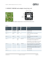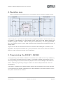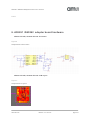
1
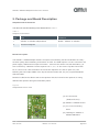
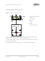
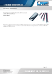
User Manual – AS5261 / AS5262 Adapterboard
AS5261-EK-AB / AS5262-EK-AB
12 BIT Magnetic Angle Position
Sensor with 2 Outputs
www.ams.com
Revision 1.0 / 2012/10/31
AS5261/ AS5262 Adapterboard User manual
Table of Contents
1.
General Description ............................................................................................................... 2
2.
Package and Board Description ............................................................................................ 3
3.
AS5261/ AS5262 and adapter board pin out ......................................................................... 5
4.
Operation case ...................................................................................................................... 6
5.
Programming the AS5261 / AS5262 ...................................................................................... 6
6.
AS5261 /AS5262 adapter board hardware ........................................................................... 7
7.
Ordering Information .............................................................................................................. 8
Copyright ....................................................................................................................................... 9
Disclaimer ..................................................................................................................................... 9
www.ams.com
Revision 1.0 / 10/31/12
page 1/10
AS5261/ AS5262 Adapterboard User manual
1. General Description
This document describes the features and operation of the AS5261 / AS5262 Adapterboard.
The AS5261 / AS5262 is a contactless magnetic angle position sensor for accurate angular
measurement over a full turn of 360°. A sub range can be programmed to achieve the best
resolution for the application. It is a system-on-chip, combining integrated Hall elements, analog
front end, digital signal processing and best in class automotive protection features in a single
device.
To measure the angle, only a simple two-pole magnet, rotating over the center of the chip, is
required. The magnet may be placed above or below the IC.
The absolute angle measurement provides instant indication of the magnet’s angular position
with a resolution of 0.022° = 16384 positions per revolution. According to this resolution the
adjustment of the application specific mechanical positions are possible. The angular output data
is available over a 12 bit ratiometric analog output.
The AS5261 / AS5262 operates at a supply voltage of 5V and the supply and output pins are
protected against overvoltage up to +20V. In addition the supply pins are protected against
reverse polarity up to –20V.
The AS5261 / AS5262 is a dual die version, with 2 independend die’s in one package. This part
can be used full redundant with 2 supplies.
www.ams.com
Revision 1.0 / 10/31/12
page 2/10
AS5261/ AS5262 Adapterboard User manual
2. Package and Board Description
Adapterboard Kit Contents
The demo kit includes following items listed below in Table 1.
Table 1:
Adapter Kit Contents
Pos
Item
Comment
1
AS5261 or AS5262 Adapterboard
Board + AS5261 or AS5262
2
Diametrial Magnets
Board Description
The AS5261 / AS5262 adapter board is a simple circuit allowing test and evaluation the rotary
encoder quickly without building a test fixture or PCB. The PCB requires a 4-wire connection: 5V
power supply, GND and two output connection . If there is the need to use full redundancy ( 6wire connection), a different PCB is required. Pin 1, 3, 5, of JP1 are the Top Die Connection.
Pin 2,4 and 6 of JP1 are the bottom die connection.Capacitor C1 and C2 (both 1uF) are
buffering the LDO output VDD3 of the top-die and the bottom-die; C3 (1uF) is placed between
VDD and GND.
Resistor R1,R2,R3 and R4 as well as the capacitor C5,C6,C7 and C8 are optional, for using
different filter options during the Evaluation phase..
Figure 2
Adapterboard front view
(A) JP1 Connector
A
( GND,VCC,OUT)
(B) AS5261 / AS5262 sensor
(C) 4 x 2.6 mm mounting
holes
B
C
www.ams.com
(D) Marking for AS5261 or
AS5262 AB Board
D
Revision 1.0 / 10/31/12
page 3/10
AS5261/ AS5262 Adapterboard User manual
Mounting the AS5261 / AS5262 adapter board
Figure 3
Adapter board with mechanical components
A
Magnet
C
B
(A) Rotating shaft and magnet
holder – Not
0.5~2mm
AS516x
ferromagnetic
D
(B) Bearing
E
(C) Casing
(D) Spacer
2
(E) M2~M2.5 Screw + nut
1
OUT
VCC
GND
JP1
4x2.6 mm
Diametral
Magnet
N
AS516x
S
A diametric magnet must be placed over or under the AS5261 / AS5262 Sensorboard, and
should be placed centered in x and y direction. Tolerance of 0.5mm
The airgap between the magnet and the encoder casing should be maintained in the range of
0.5mm~2mm ( magnet related).
The magnet holder must be not ferromagnetic. e.g copper, aluminium, stainless steel.
www.ams.com
Revision 1.0 / 10/31/12
page 4/10
AS5261/ AS5262 Adapterboard User manual
3. AS5261/ AS5262 and adapter board pin out
VDD_B
VDD_T
OUT_B
OUT_T
16
15
14
13
NC_T 1
NC_B
12 S_B
2
11 S_T
Epad
VDD3V3_T 3
10 NC_B
VDD3V3_B 4
9 NC_T
7
8
NC_T
NC_B
GND_T
6
GND_B
5
Figure 4 AS5261/AS5262 adapterboard connectors and sensor pinout
Table 2:
Pin Out
Pin#
Pin#
Symbol
Type
Description
Board
AS5261/62
Board
JP1 - 1
1,2,4,5,7,8
GND
S
Supply ground
JP1 - 2
1,2,4,5,7,8
GND
S
Supply ground
JP1 - 3
15,16
VCC
S
Positive supply pin (overvoltage
protected)
JP1 - 4
15,16
VCC
S
Positive supply pin (overvoltage
protected)
JP1 - 5
11,13
OUT
DIO/AIO
Top
Output and interface pin. Provides PWM
on TopOutput on the AS5261 and
Analogoutput on the AS5262 .It is as well
used for programming UART interface
JP1 - 6
12,14
OUT
DIO/AIO
Top
Output and interface pin. Provides PWM
on BottomOutput on the AS5261 and
Analogoutput on the AS5262 .It is as well
used for programming UART interface
JP1 - 7
Not connected
JP1 - 8
Not connected
www.ams.com
Revision 1.0 / 10/31/12
page 5/10
AS5261/ AS5262 Adapterboard User manual
4. Operation case
Figure 5 Operation Case example pull up. This operation case is working for AS5261 as well.
The OUT pin (JP1 – 5) is used as output as well as programming interface. After the first power up,
the AS5261 or the AS5262 is in communication mode. During this mode different settings are
possible to program. via UART . After the fusing of the internal OTP ( one time programmable )
block, the AS5261 provides a pulse width modulated output (PWM) and the AS5262 provides an
analog output,
Figure 5 shows the recommended schematic for AS5261 and AS5262(pull up solution) in the
application. All components marked with (*) are optional and can be used to further increase the
EMC.For further information, please refer to datasheet.
5. Programming the AS5261 / AS5262
For programming of the AS5261 / AS5262 4 connections (VCC, GND and OUTTop, OutBottom)
or 6 connections (full redundant) are necessary. The AS5261 /AS5262 programming is a onetime-programming (OTP) method, based on polysilicon fuses. The advantage of this method is
that no additional programming voltage is needed. The internal LDO provides the current for
programming.
The AS5261 / AS5262 uses a standard UART interface with an address byte and two data byte.
For programming the AS5261 / AS5262 there is a DemoSoftware ( Executable Labview) and an
easy UART-Interfaceboard available.
www.ams.com
Revision 1.0 / 10/31/12
page 6/10
AS5261/ AS5262 Adapterboard User manual
FOTO
6. AS5261 /AS5262 adapter board hardware
AS5261-EK-AB; AS5262-EK-AB Schematic
Figure 6
Adapterboard Schematic
AS5261-EK-AB; AS5262-EK-AB PCB layout
Figure 7:
Adapterboard Layout
www.ams.com
Revision 1.0 / 10/31/12
page 7/10
AS5261/ AS5262 Adapterboard User manual
7. Ordering Information
Table 2:
Ordering Information
Ordering Code
Description
comments
AS5261-EK-AB
Adapterboard
3 diametric magnets
AS5261-EK-AB
Adapterboard
3 diametric magnets
www.ams.com
Revision 1.0 / 10/31/12
page 8/10
AS5261/ AS5262 Adapterboard User manual
Copyright
Copyright © 1997-2012, ams AG, Tobelbader Strasse 30, 8141 Unterpremstaetten, Austria-Europe.
Trademarks Registered ®. All rights reserved. The material herein may not be reproduced, adapted, merged,
translated, stored, or used without the prior written consent of the copyright owner.
All products and companies mentioned are trademarks or registered trademarks of their respective companies.
Disclaimer
Devices sold by ams AG are covered by the warranty and patent indemnification provisions appearing in its
Term of Sale. ams AG makes no warranty, express, statutory, implied, or by description regarding the
information set forth herein or regarding the freedom of the described devices from patent infringement. ams
AG reserves the right to change specifications and prices at any time and without notice. Therefore, prior to
designing this product into a system, it is necessary to check with ams AG for current information.
This product is intended for use in normal commercial applications. Applications requiring extended
temperature range, unusual environmental requirements, or high reliability applications, such as military,
medical life-support or lifesustaining equipment are specifically not recommended without additional
processing by ams AG for each application. For shipments of less than 100 parts the manufacturing flow might
show deviations from the standard production flow, such as test flow or test location.
The information furnished here by ams AG is believed to be correct and accurate. However, ams AG shall not
be liable to recipient or any third party for any damages, including but not limited to personal injury, property
damage, loss of profits, loss of use, interruption of business or indirect, special, incidental or consequential
damages, of any kind, in connection with or arising out of the furnishing, performance or use of the technical
data herein. No obligation or liability to recipient or any third party shall arise or flow out of ams AG rendering of
technical or other services.
Contact Information
Headquarters
ams AG
Tobelbader Strasse 30
8141 Unterpremstaetten
Austria
T. +43 (0) 3136 500 0
For Sales Offices, Distributors and Representatives, please visit:
http://www.ams.com/contact
www.ams.com
Revision 1.0 / 10/31/12
page 9/10
Mouser Electronics
Authorized Distributor
Click to View Pricing, Inventory, Delivery & Lifecycle Information:
ams:
AS5262-EK-AB AS5261-EK-AB