1
EML 4905 Senior Design Project
A B.S. THESIS
PREPARED IN PARTIAL FULFILLMENT OF THE
REQUIREMENT FOR THE DEGREE OF
BACHELOR OF SCIENCE
IN
MECHANICAL ENGINEERING
Autonomous Irrigation Robotics System
100% Report
Armando Camacho
Frank Azcuy
Benjamin Sturman
Advisor: Dr. Sabri Tosunoglu
November 22nd, 2015
This B.S. thesis is written in partial fulfillment of the requirements in EML 4905.
The contents represent the opinion of the authors and not the Department of
Mechanical and Materials Engineering.
Ethics Statement and Signatures
The work submitted in this B.S. thesis is solely prepared by a team consisting of Armando
Camacho, Frank Azcuy, and Benjamin Sturman and it is original. Excerpts from others’ work
have been clearly identified, their work acknowledged within the text and listed in the list of
references. All of the engineering drawings, computer programs, formulations, design work,
prototype development and testing reported in this document are also original and prepared by
the same team of students.
Armando Camacho
Team Leader
Frank Azcuy
Team Member
Dr. Sabri Tosunoglu
Faculty Advisor
ii
Benjamin Sturman
Team Member
TABLE OF CONTENTS
Chapter
Page
Cover Page
Ethics Statement and Signatures
Table of Contents
List of Figures
List of Tables
i
ii
iii
vi
vii
Abstract
1
1. Introduction
2
1.1 Problem Statement
2
1.2 Motivation
3
1.3 Literature Survey
4
1.4 Survey of Related Standards
7
2. Project Formulation
8
2.1 Overview
8
2.2 Project Objectives
9
2.3 Design Specifications
10
2.4 Addressing Global Design
11
2.5 Constraints and Other Considerations
13
3. Design Alternatives
14
3.1 Overview
14
3.2 Design Alternate 1
15
3.3 Design Alternate 2
16
3.4 Design Alternative 3
17
3.5 Integration of Global Design Elements
18
3.6 Feasibility Assessment
20
3.7 Proposed Design
22
iii
4. Project Management
24
4.1 Overview
24
4.2 Breakdown of Work into Specific Tasks
25
4.3 Gantt Chart for the Organization of Work and Timeline
28
4.4 Breakdown of Responsibilities among Team Members
29
4.5 Commercialization of the Final Product
31
5. Engineering Design and Analysis
32
5.1 Overview
32
5.2 Kinematic Analysis and Animation
33
5.3 Force Analysis
36
5.4 Structural Design
38
5.5 Stress Analysis
39
5.6 Deflection Analysis
41
5.7 Flow Analysis
42
5.8 Thermal Analysis
45
5.9 Material/Component Selection
47
5.10 Cost Analysis
49
5.11 Design Overview
50
6. Prototype Construction
51
6.1 Description of Prototype
51
6.2 Prototype Design
52
6.3 Parts List
55
6.4 Construction
57
6.5 Prototype Cost Analysis
63
6.6 Programming and Path Finding
64
6.7 Discussion
67
iv
7. Testing and Evaluations
68
7.1 Overview
68
7.2 Design of Experiments – Description of Experiments
69
7.3 Test Results and Data
75
7.4 Evaluation of Experimental Results
82
7.5 Improvement of Design
83
7.6 Discussion
84
8. Design Considerations
85
8.1 Health and Safety
85
8.2 Assembly and Disassembly
87
8.3 Manufacturability
89
8.4 Maintenance of the System
91
8.5 Environmental Impact and Sustainability
92
8.6 Economic Impact
93
9. Design Experience
95
9.1 Overview
95
9.2 Standards Used in the Project
96
9.3 Impact of Design in a Global and Societal Context
97
9.4 Professional and Ethical Responsibilities
99
9.5 Life-Long Learning Experience
101
9.6 Discussion
102
v
10. Conclusion
103
10.1 Conclusion and Discussion
103
10.2 Evaluation of Integrated Global Design Aspects
104
10.3 Evaluation of Intangible Experiences
106
10.4 Commercialization Prospects of the Product
108
10.5 Future Work
110
References
112
Appendix
115
A.1 Technical Drawings
115
A.2 User Manuals
116
A.3 Sample Code
125
vi
LIST OF FIGURES
Figure
Page
Figure 1: Conventional Sprinkler System [2]
3
Figure 2: Water Walker System [4]
4
Figure 3: Droplet Robotics Sprinkler [5]
5
Figure 4: An Autonomous Robotic Vacuum Cleaner [6]
6
Figure 5: Four Wheel Mecanum Drive Robot [11]
15
Figure 6: Three Wheel Omni Robot
16
Figure 7: iRobot Create 2 Programmable Robot [12]
17
Figure 8: Rotating Support Shaft into a Bearing within the Sprinkler Mounting Bracket
33
Figure 9: Sprinkler Base Plate Shown in Yellow
34
Figure 10: Roller Bearing to be used in Shaft
34
Figure 11: Force Vector on Robot Sprinkler Structure
36
Figure 12: Sprinkler Mounting Assembly
38
Figure 13: Stress Analysis of Sprinkler Mounting Bracket Assembly
39
Figure 14: Sprinkler Mounting Bracket in Detail
40
Figure 15: Deflection Analysis on Sprinkler Mounting Bracket
41
Figure 16: Moody Diagram [14]
43
Figure 17: Thermal Study during Worse Case Temperatures
45
Figure 18: Arduino Housing
52
Figure 19: ARSS Chassis
53
Figure 20: ARSS Chassis
57
Figure 21: 3D Printed Bin Tray and Wiring
57
Figure 22: Tapping of Sprinkler Base
58
Figure 23: Sprinkler Support Structure
59
Figure 24: 16x2 LCD Screen
60
Figure 25: Digital Flowmeter
60
Figure 26: Distance Sensor
61
Figure 27: Completed Assembly
61
vii
Figure 28: Pathing Diagram Array
64
Figure 29: Experiment #1 Stress Test Set-up
69
Figure 30: Experiment #2 Stress Test Set-up
70
Figure 31: Experiment #3 Battery Testing Set-up
71
Figure 32: Experiment #4 Watering Radius Set-up
72
Figure 33: Experiment #5 Temperature Testing Set-up
73
Figure 34: Experiment #1 Resulting Failure
75
Figure 35: Experiment #2 Shaft Stress Test
76
Figure 36: Experiment #4 Watering Diameter
78
Figure 37: Experiment #5 Initial Robot Temperature with Sprinkler Base Cover
79
Figure 38: Experiment #5 Final Temp. Reading at 15 Minutes with Sprinkler Base Cover
80
Figure 39: Experiment #5 Initial Temperature Reading with no Sprinkler Base Cover
80
Figure 40: Experiment #5 Final Temp. Reading at 15 Minutes without Sprinkler Base Cover
81
viii
LIST OF TABLES
Table
Page
Table 1: Gantt chart
28
Table 2: Material Selection/Design
47
Table 3: Cost Analysis
49
Table 4: Prototype Cost Analysis
63
Table 5: Experiment #1 Testing Results
75
Table 6: Battery Life Testing Results
77
Table 7: Initial and Final Temperatures
81
ix
Abstract
For this project, the goal is to design a system that is capable of autonomously
administering water and plant nutrients over a grassy terrain within the boundaries specified by
an end user. This will be accomplished by designing a weather proof chassis that houses onboard
electronics that will be responsible for the autonomous behavior desired.
The water delivery system will be a lightweight hose that is resistant to kinking, catching
on obstacles, or becoming entangled. In order to further mitigate this issue, the hose attachment
on the robot will be able to rotate in any direction so that the hose is always facing towards the
main water source.
The power source will be an onboard battery that will be charged by a charging station
that will be installed where the end user desires. This charging station will also double as the
“home” port for the robot itself.
1
1. Introduction
1.1 Problem Statement
In the past decade, the field of robotics has grown considerably in a short amount of time.
There are countless innovations in robotics applications that are available to consumers because
robots have become relatively cheap to buy and/or build. For example, Unmanned Aerial
Vehicles (UAVs) and manufacturing processes have benefitted from this booming industry. The
possibilities for the applications of robots and autonomous systems are only restrained by the
designer’s creativity.
Unfortunately, in the field of agriculture, specifically in residential lawn care, little
advancements have been made that take advantage of the benefits that the field of robotics can
offer. There is a lack of products and systems at the residential level that can water lawns and
this is due to the fact that very few companies are conducting product development in this
specific area.
Caring for and maintaining a yard requires time and resources to insure that it is healthy
and aesthetically pleasing to the eye. Designing an autonomous robot that can water a given area
such as a residential lawn can make maintenance of the area far more efficient and cost effective.
2
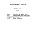
1.2 Motivation
One main components of lawn care is watering the lawn itself and its surrounding plants.
This action alone is simple, yet time consuming enough to create a system to do it autonomously
and more importantly, in an efficient fashion. A robot that is capable of watering a lawn
autonomously is a very convenient and cost-effective product. Due to the cost of sprinkler
installations and ongoing maintenance costs, conventional sprinkler systems can be expensive
[1]. Additionally, dry areas that cannot be reached by use of these conventional sprinkler systems
can now be watered by the mobility of the robot. The largest benefit for the environment is the
conservation of a vital natural resource and that resource is water.
Figure 1: Conventional Sprinkler System [2]
3
1.3 Literature Survey
Currently, there are a few products on the market that are capable of being considered as
moving sprinklers. Figure 2 shows a system called the Water Walker that uses the hydraulic
pressure available through a traditional garden hose to move forward and water its surroundings
[3].
Figure 2: Water Walker System [4]
The main issue with the Water Walker is its inability to move freely in any direction and
must travel along a unidirectional predetermined path set by a hose in order to move. This track
is required to be laid down and picked up every time it is used. If not, it will be unsightly and can
possibly damage the grass over time. This track placement by the end user makes this product
non-autonomous as well as tedious. It also moves at a very slow place making the possibility of
over watering, which can cause damage to the lawn an issue.
4
A currently available product for autonomous plant watering is the Droplet Robotics
Sprinkler [5]. It is capable of connecting to databases in order to check weather patterns [5]. This
allows it to calculate how much watering is needed or if watering is required at all. Figure 3
shows a product illustration.
Figure 3: Droplet Robotics Sprinkler [5]
This system is autonomous and requires little to no human input, but is unable to move
about freely and only has an effective range of 30 feet [5]. Therefore, several units would be
required to achieve complete coverage for a medium sized yard. These units are expensive and
require a conveyor such as a hose in order to transport water to the unit. These hoses may not be
ideal for an end user concerned with aesthetics and cost. If a new area is to be watered by this
system, relocation would be required for both the robot and the water connection which may be
time consuming and cumbersome.
5
In the market, there exists several autonomous vacuum cleaners whose operating
functions are very similar to what this project intends to achieve, covering a large space
autonomously with object avoidance. However in this case, instead of cleaning a floor, an area
will be watered. These autonomous vacuums are appropriately sized, battery powered, and can
clean an entire floor of a house effectively [6].
Figure 4: An Autonomous Robotic Vacuum Cleaner [6]
Figure 4 shows one such example of an autonomous robotic vacuum cleaner. These
robots functionality, usefulness, and overall market share prove that a sprinkler robot is
definitely a feasible product. The advantage of choosing a sprinkler design that is autonomous
and mobile is that it has a much larger effective range while requiring no human input. Once the
system is finished with its watering routine, it can return to its charging station, and prepare for
the next watering cycle as set by the end user. The modifications required for a robot with a
sprinkler design would be to design it with the harsh elements that come from an external
environment such as rain, snow, heat, and dust while making sure that it is capable of traversing
tough terrain.
6
1.4 Survey of Related Standards
The design of any system must adhere to constraints and standards set by a regulating
body that specializes in the design of said system. The Occupational Safety and Health
Administration (OSHA) Standard Number 1910.211 and ISO 13482:2014 has requirements and
procedures in place for the safe operation of robots by end users [7] [8]. In the case of the
autonomous sprinkler system being designed, it must be safe to approach if the user wants to
modify or relocate the system manually while the system is in operation. Integrating a sensor into
the sprinkler system that turns off the sprinkler assembly when animals or humans approach
would be a requirement set forth by this standard.
For irrigation systems, the Irrigation Association (IA) & American Society of Irrigation
Consultants (ASIC) state that an irrigation system shall be designed so as to distribute water at a
safe and efficient flow rate while adhering to local regulations on water use and consumption [9].
Some additional considerations are to include a mechanism that can record the amount of water
used for future management of water consumption data, prevent runoff water or unnecessary
watering of areas [9]. Other consideration would be to protect the system from harsh weather
conditions such as freezing temperatures as well as measures to prevent vandalism of the system.
A full outline of these standards can be found on the IA website.
The Institute of Electrical and Electronics Engineers (IEEE) places standards on the
safety of electronic systems. IEEE 802.11 states that wireless transmissions of devices shall not
interfere with nearby systems where the interference may create a safety hazard [10]. In the event
of electrical failure, a failsafe should be implemented to prevent any large scale damage to the
surrounding area or persons [10].
7
2. Project Formulation
2.1 Overview
In this chapter, project objectives will be discussed as well as an introduction to the
design that is being considered. Along with this discussion, design specifications will also be
presented and the reasons why they are required in order to create an effective system that is
capable of meeting project objectives. In addition, a major subject of this project is global design
and how it will be addressed to ensure that the design is globally conscious and friendly. Finally,
constraints and other considerations will be brought forth at the end of the chapter and the steps
taken to account for these constraints.
8
2.2 Project Objectives
The main goal for this project is to design a new irrigation system. The Autonomous
Irrigation Robotics System (ARSS) which will be for use in residential lawn care applications.
More specifically, an autonomous robot that requires minimal human interaction in order to
function similarly to a conventional sprinkler system. An onboard computer can perform the
necessary calculations and actions required in order to maneuver the system once first time set
up is completed.
Additionally, this system needs to be just as, if not more, efficient as a conventional
sprinkler system and remain environmentally friendly. Taking these objectives into
consideration, an autonomous sprinkler system can be a suitable replacement to any sprinkler
system currently in use today.
Keeping the cost low is an important objective in order to facilitate widespread adoption
for the majority of current consumers. Furthermore, it should be a viable replacement for current
systems that require lengthy construction, high initial costs, costly maintenance, or a possible
choice for first time owners interested in lawn care.
9
2.3 Design Specifications
ARSS will have several features that will provide a realistic alternative to several
different lawn watering systems offered to consumers. A reasonable alternative requires a cost
benefit over other systems. So an important design specification is the requirement of a low cost
system that is relatively inexpensive to manufacture.
As a residential lawn care product, the ARSS system should be lightweight and easy to
move in the event of relocation of the system. Ease of use is another main design specification.
Therefore, a friendly user interface that the end user will interact with to instruct the ARSS as
well as simple first time set up will be a design goal. Moreover, a valve which affects the
effective radius of the robot can be used for smaller sized lawns.
There are several methods to providing power to a system, but in the case where the
ARSS will be located outside most of the time; solar energy is a reliable and sustainable energy
source. Keeping global awareness and environmental consequences in mind, solar energy is the
most natural but most involved decision for powering ARSS. Hydraulic pressure is another
possibility where the pressure from the residential water source can be used to power certain
components of the robot.
Perhaps the most important design feature is the requirement of ARSS being able to
withstand several harsh weather conditions such as rain, snow, hot, and humid weather or
combinations of these conditions. Failure to account for these factors may lead to premature
failure of the system by overheating or water damage.
The integration of sensors into ARSS such as proximity sensors, humidity sensors, and
temperature sensors among several will create a smart robot that can make decisions on how
much to water or if watering the area is required at all.
10
2.4 Addressing Global Design
In a fast paced world where standards are commonplace, there needs to be an order of
consistency between different standards that account for the same phenomena. One dominant
example for this that still creates problems today is the use of both the SI as well as the Imperial
system of measurements. The United States continues to use the Imperial system in an economy
where the SI system is the dominant standard for measurements among most countries. One
global learning component that can be used in this project would be the use of both measurement
systems to expand the reach of this project to other parts of the world outside of the United
States.
Machines today are more complex than they have been in past centuries. With added
complexity to these systems, their inherent danger is much more real and apparent. If a project or
product is to be used around the world, one of the biggest obstacles would be the language
barrier among countries. There are hundreds of languages in the world with only a few major
ones so the most realistic goal would be to create manuals in 3 or more languages and use
industry standard danger symbols to alert any users of serious injury no matter what language
they may speak.
Creating a safe operating environment for any system is crucial to widespread adoption in
a global sense. Taking into account different backgrounds and making sure the users are safe no
matter the language barrier is a first step in global design.
A major problem today that is a controversial topic is climate change caused by industrial
processes and secondary sources of pollution. Around the world, manufacturing processes
release millions of tons of greenhouse gases every year. Recent movements and laws have
caused companies to rethink manufacturing designs to be more environmentally friendly.
11
In most countries, there is an official currency that is used for the purchase of goods and
services within its borders. Due to economic conditions within the country and other external
factors such as location and resources, the relative value of any currency can be worth more or
less when compared to other currencies. One example is the Euro and the Dollar and how their
different values can cause problems when products are sold overseas.
Conducting a cost analysis in different currencies and locations can help demonstrate
how it may be preferable to conduct business/manufacturing in another country because of the
price of resources and labor. At the same time, differing prices can be set to stifle income
inequality in several countries. A product that can be sold at a high profit margin in the United
States can be sold at a much lower price in developing countries while still profiting from sales.
Due to the lack of standardization across several countries in power grid design and outlet
designs found in homes, there exists a variety of connections and adapters in order to
accommodate several products created in different parts of the world. One issue that always
occurs in the design of electrical components is how a 110/220V or 50/60Hz system will be
integrated into an existing or changing design. Changing the design to allow for this is an
important aspect of creating a product or system that can be used anywhere in the world
regardless of electrical standards.
12
2.5 Constraints and Other Considerations
As with every project, constraints are unavoidable and must be accounted for. The ARSS
system must carry its weight as well as the weight and friction that come as a result of carrying a
hose along with it. The system should not weigh so much as to prevent movement of the robot as
it carries it out its task. The robot should be manufactured with weight in mind.
As the ARSS moves around the boundary to be watered, the location and position of the
hose must be kept in mind because possible blockages or tangling may occur which will prevent
normal operation. A light weight hose must also be paired with a programmed behavior where
the robot will always have its fluid inlet pointing in the direction of the water source. This will
reduce the possibility of tangling and aid the robot to maneuver more effectively.
Outside the realm of design, local watering regulations must be obeyed and is at the sole
discretion of the end user. Moreover, to prevent mishaps of water wastage, should the system be
unable to move about because of blockages or obstructions, a check will be made by onboard
instruments every minute to make sure that in the event that a blockage does occur, the water
source will be turned off.
Yards come in several shapes and sizes and in the event that a yard is too small, the flow
rate can be modified using the system interface to decrease the watering radius of the sprinkler.
Furthermore, yard owners may have more than one area to be watered so different profiles may
be set on the robot where the appropriate profile can be selected for the corresponding area to be
watered.
13
3. Design Alternatives
3.1 Overview
As previously mentioned due to the various obstacles that the ARSS may encounter in
one’s yard, and the fact that it will be outdoor constantly, there will many critical parameters that
need to be considered in all design alternatives. First is the use of a sensor and control system in
order for the robot to determine the area that the user defined as needing to be watered. Second,
because the robot will be primarily outdoors, it will need the necessary motors and proper wheels
to travel over any obstacles found in a typical household. The robot will also need to be designed
to be weather resistant due to the many elements it may encounter outside. Finally, one of the
robot’s most crucial parameters, the hose system, must be designed so that it will be able to
water an area as efficiently as possible without getting tangled with itself or anything else it may
encounter. These critical parameters will be incorporated in all the design alternatives as well as
other parameters that will be discussed in further detail in the next sections.
14
3.2 Design Alternate 1
The primary focus for each design alternative is the orientation of the hose nozzle with
respect to the main water source. It is for this reason that this design allows the robot to strafe
from left to right, ensuring that the nozzle is always pointed in one direction. This is achieved by
using four Mecanum wheels with their own separate electric motors. With four motors, this will
help the robot gain traction. An added advantage to having the robot move in this motion is to
allow more freedom in avoiding objects effectively [11].
Figure 5: Four Wheel Mecanum Drive Robot [11]
The disadvantage with type of drive system is that these wheels cannot be used on
various surfaces. This is due to the lack of grip these wheels can provide. Another issue with this
drive system is that it will not be able to climb over obstacles. Finally, because this is a specialty
drivetrain, it is very expensive which might deter consumers from buying this product [11].
15
3.3 Design Alternate 2
The second design alternative has a three Omni wheel drivetrain. Similar to the first
design alternative, this drive system allows for the robot to travel in any direction. However
because it has one less wheel, the orientation of each wheel is angled so that it still has the same
maneuverability as a four wheel drivetrain.
Figure 6: Three Wheel Omni Robot
This design focuses on taking the positives from the previous design but at the same time
cutting the overall cost. By removing one wheel and one motor, is it possible to significantly cut
the material cost of the robot. Even though the second design alternative addresses some issues
such as cost and maneuverability, the robot with the use of this drive system will not have the
necessary traction to be used on grass.
16
3.4 Design Alternative 3
The final design alternative is a two wheel, circular robot similar to the Roomba shown
below. Each wheel will be powered separately with their own individual electric motors. It will
contain a rechargeable battery pack as well as various sensors to determine its location and return
home to the docking station [12].
Figure 7: iRobot Create 2 Programmable Robot [12]
Where it varies is in the size of the wheels and motors in order to compensate for any tall
grass or slopes that the robot may encounter outside. Also, since it will not have the same
maneuverability as the previous design alternatives, the hose attachment on the robot will be
designed to rotate as the robot changes direction. This will help ensure that the hose will not get
tangled on the robot.
17
3.5 Integration of Global Design Elements
The integration of global design elements will begin with the first and foremost important
aspect of the ARSS system. How will it charge and operate using various power grids. Within
the ARSS there will be a space specifically designed to house a transformer so that it will be
usable on all types of power grids. For example, countries that run on 220V with 50Hz will have
the same base model ARSS sent to them as the ones in the United States. However, during
manufacturing different transformers will be installed depending on their end destination. In
order to adjust for the two most common power grid configurations there will be models that
utilize 120V at 50/60Hz as well as 220V at 50/60Hz using these transformers.
Safety is a top priority for the ARSS as it will be marketed to the everyday consumer.
Due to this fact, a large number of safety factors and precautions will be introduced into the
ARSS system. First and foremost will be clearly visible warning labels on the ARSS itself.
Cautionary warnings against electric shock, touching and/or transporting the ARSS while it is in
operation, and other pertinent warning labels required by the aforementioned standards will be
implemented. Other safety factors include onboard sensors to monitor the ARSS during
operation. A pressure sensor to monitor the flow of water within the system will turn the system
off if pressure becomes too high or low. Temperature sensors will be implemented within the
system as well so as to prevent a meltdown or possible explosion due to fluid leakage.
Higher levels of detailed warnings for operation will be included within the manual of the
ARSS system. This operation/safety manual will be available in the language of whatever
country that the ARSS is sold in. These manuals will include detailed instructions on the set up,
usage, maintenance, safety precautions, and storage of the ARSS system.
18
The calculations and final specifications of the ARSS system will be done and presented
using the SI unit system. However, similar to the language translations available, US units will
be converted and available on the United States models.
19
3.6 Feasibility Assessment
The feasibility of any new product design must be weighed using its pros and cons, the
innovations as well as the roadblocks. These pros and cons are based mostly off of the advances
in robotics that have been made recently as well as technology that has been available.
One of the aspects of current autonomous technology that is a benefit to the ARSS is the
tracking system shown in the Roomba Create 2. This type of system utilizes onboard sensors and
memory to avoid obstacles while also recalling and tracing the predetermined paths needed to
clean the room [12]. This is a feature that is applicable to the ARSS as it solves many of the
problems mentioned previously. A few of them being object and obstacle avoidance, proximity
sensors for pets and humans, and proper mapping when traveling to locations that need watering.
Finally, the software will be designed for a simple one time user input during the initial set up of
the ARSS.
Current battery advances have allowed for components to be small enough to fit onto the
ARSS without causing a hindrance to the overall weight or maneuverability of the system. The
docking station to be used as the home “base” for the ARSS has also been tested and proven to
be an effective and feasible method for the updating and charging of an autonomous robotic
system.
Similarly, servos and motors have become smaller, more powerful, and their efficiency
has improved. This will allow the ARSS to employ small servomotors in order to power each of
its wheels. These motors will allow the ARSS to traverse rougher terrains, higher grass, and even
small obstacles such as sticks or rocks in order to reach its destination.
20
The rotational base for the sprinkler apparatus on top of the ARSS allows it to turn in any
direction while simultaneously keeping its supply hose pointed in the direction of the water
source. This will diminish the torque that would have been applied to the ARSS which can cause
wear and tear on the sprinkler apparatus as well as pulling the ARSS off course.
IR technology allows for a very precise and strong communication network for the
directional/location system of the ARSS. IR can be used to update the onboard systems in order
to eliminate the need for another plug and or connection on the home dock. This will ensure that
ease of docking is maintained while also extending the longevity of the system.
The feasibility of the ARSS is high due to the recent advancements in robotics as well as
the already proven and available autonomous robots on the market today. Examples of these
autonomous robots are the Roomba Create 2, the Water Walker System, and the Droplets Water
Sprinkler. The goal with this design is to build upon the already established robotic principles
demonstrated by already existing autonomous robots. By adding modifications and unique ideas
to these principles, it is believed that the ARSS will be able to perform just as effectively as its
predecessors.
21
3.7 Proposed Design
The proposed design for the ARSS will utilize the Roomba Create 2 platform. It will
consist of a powerful two wheel drivetrain and a charging station. To facilitate the robot’s
maneuverability around the customer’s backyard, the ARSS will be fitted with multiple sensors.
These various sensors will be able to detect any objects it might collide into, determine if it has
rained recently, and avoid any sharp drops that might damage the robot.
Another design standard that will be implemented to the ARSS will be to keep its entire
critical electrical components waterproof. In doing so, this will ensure that the components won’t
get damaged while the sprinkler head is running. Also, because the ARSS will mostly remain
outdoors, it will be manufactured with high grade materials to certify the robot will have a long
life.
The sprinkler system on the robot will consist of a rotating sprinkler head, rotating base,
hose retrieval system, and a variable water valve. The rotating sprinkler head was chosen
because it is the most efficient and versatile way to water an area. The variable water valve helps
conserve water as well as give the customer freedom to adjust the effective range of the ARSS
sprinkler depending on the size of their yard. In order to prevent the ARSS from tangling itself
with the hose, the sprinkler head will be attached to a rotating base which will originate from the
center of the robot. This rotating base will be attached to the robot with a sealed roller bearing to
allow it to rotate with minimal friction. The hose retrieval system will consist of a torsional
spring that will allow the robot to move freely while keeping enough tension so it can recover the
hose.
22
As previously mentioned, the robot will be programmed to determine where it is in
relation to the charging station, while avoiding collision with objects and falling down steep
slopes. It will also be able to conserve water by turning off the water supply if it gets stuck in one
location for a long period of time. The customer will be able to monitor the status of the ARSS
on their Apple or Android device. Within the application, multiple programmable irrigation
profiles can be created if there is more than one area that is to be watered.
23
4. Project Management
4.1 Overview
The Autonomous Robotics Sprinkler System’s three key areas of design will be:
hardware testing and integration, programming and user input, and finally electronics
modification and integration. Hardware and electronics modification are two different fields that
will eventually be conjoined together to complete the final design. Programming however is a
separate task without requiring as much input from the hardware and electronics areas as these
do not directly affect the code itself.
24
4.2 Breakdown of Work into Specific Tasks
The breakdown of the individual tasks for hardware, electronics, and programming will
be as follows. For hardware, chassis modification to the Roomba will be made in order to help
for traversing grass and small obstacles. This will include possible motor upgrades, wheel
tread/size changes, any alterations to the frame of the robot when incorporating the various
sensors, and waterproofing electronics inside.
The sprinkler system which includes a servo motor to control the effective radius, water
flow sensor, hose retrieval, and payout system must be designed. This system will be modeled
after the electric cord retrieval systems employed on large yachts and commercial vessels in the
marine industry. The system will include a motor to payout and retrieve the hose, a limiting
switch to start and stop the motor in conjunction with the movements of the ARSS, as well as a
receptacle for storing the hose when not in use.
The docking station for the ARSS will be a modified, more robust version of the Roomba
chassis’ original docking station designed for outdoor use. This will include waterproofing the
system, creating a platform for the ARSS to rest on while not in use so as to avoid mold and
outdoor degradations to the system.
In terms of electronics, the ARSS will incorporate sensors such as humidity, temperature,
barometric pressure, fall/flip over, and collision detection. These sensors and servos will be
controlled using the Arduino Uno microcontroller. This is where the hardware and electronics
will become integrated piece by piece as the microcontroller as well as all of its peripheral I/Os
are incorporated into the ARSS chassis. A cool, padded, and waterproof location inside the
chassis will be designed and used to house Arduino Uno.
25
The sensors will be placed at strategic locations on the chassis so as to be able to provide
optimal data for the operation of the ARSS. This will include modifying the chassis to
incorporate the sensors as well as modifying the sensors themselves so that they will be able to
stand up to the outdoor elements. As previously mentioned, the hose retrieval system while
largely mechanical will have an electronic component in the form of a motor and a limiting
switch which will be the controller for the motor itself. These will be calibrated so as to provide
the proper amount of retrieval and payout tension on the hose as the ARSS waters the lawn. This
system will be incorporated so as to avoid entanglements as well as keep the load of the ARSS as
light as possible by not dragging any unnecessary extra length of hose that the robot will have to
pull around the yard with it.
The ARSS will have a small LED screen incorporated into the ARDUINO for the initial
set up. This will require a space to be made on the ARSS chassis for the screen as well as
weatherproofing the screen so as to protect from outside contaminants.
Since these electrical components will be utilized, there will be a significant amount of
programming. All programming for the Arduino will be done in its native language (Arduino
Software IDE), and any supplemental programming will be done in C++. The Arduino Uno will
be programmed to interface with the built in sensors on the Roomba chassis as well as the
directional and memory functions of the system. These systems are critical for determining and
executing the watering pattern for the end users yard. The Arduino will be programmed to
receive inputs from the sensors and subsequently control the ARSS based upon the temperature,
barometric pressure, and humidity. The temperature and humidity sensors will be used to
deactivate the ARSS on wet, rainy days so as to conserve water and protect the lawn from
overwatering. The ARSS will be programmed to provide a simple one time user interface for
26
initial set up. This set up will have the user input: lawn size, watering intervals, path of watering
and obstacles in the lawn.
27
4.3 Gantt Chart for the Organization of Work and Timeline
Table 1: Gantt chart
28
4.4 Breakdown of Responsibilities among Team Members
Armando Camacho.
Major Role: Programming, Support Role: Electronics and Hardware.
Armando will be the leader and primary programmer for the Arduino Uno and Roomba chassis.
This will involve programming the Arduino to recognize and utilize all sensors for the system
and incorporate them into the everyday function of the ARSS. Other tasks include writing the
end user initial set up program as well as the internal operation code for the ARSS itself as
described in section 4.2. Armando will be supported by Frank Azcuy, and Benjamin Sturman.
Frank Azcuy.
Major Role: Electronics, Support Role: Programming and Hardware.
Frank will be the leader and primary integrations specialist for all of the electronics that will be
place in and on the ARSS. This will involve the calculation of power levels, conversions, wiring,
collaborating with Benjamin on the hardware side to ensure all parts fit, collaborating with
Armando to ensure all programming is synchronized as well. Support will be provided by
Armando Camacho and Benjamin Sturman as required.
Benjamin Sturman.
Major Role: Hardware, Support Role: Electronics and Programming.
Benjamin will be the leader and head designer on the chassis modifications as well as the
preparations and calculations of all the parts used on the ARSS. Weatherproofing and
waterproofing all the electronic components of the ARSS, preventative measures (lubrication and
greasing) for metallic and moving parts. This will involve the calculation of strains and stresses
29
on the vital areas of the system such as motor shafts, wheels, bearings, hose attachments, hose
retrieval system, and couplings. Other duties will include the design and integration of the hose
retrieval system where he will work in conjunction with Armando to design the electrical
systems involved. Finally, any hardware on the original Roomba chassis which needs to be
replaced or redesigned for outside use will be his responsibility as well.
30
4.5 Commercialization of the Final Product
Commercialization of the Autonomous Robotics Sprinkler System will begin with initial
testing within small markets. South Florida will be the initial test market, as the flat land and
deep grasses that are more common will provide a solid testing background. It is believed that if
the ARSS is able to operate on the deep and thicker grasses and sandy soil of Florida that it will
be able to operate anywhere in the United States. Once the personal ARSS system is up and
running, it can expand into other markets. This will involve approaching a company such as G3
Engineering Design Inc. who will be able to take this project and help work towards a
commercial level product [13]. Once initial testing, feedback, modifications have been finished
and a reliable product has been established it, will be time to take the ARSS to a commercial
factory level of production.
31
5. Engineering Design and Analysis
5.1 Overview
In this chapter, several analyses will be conducted on the ARSS which help support the
feasibility of the project as well as the design that is planned to be put into use in the first
prototype. Starting with the kinematic analysis, the topic of how all moving parts and how the
robot will behave during operation will be discussed followed by an animation which will
provide a visualization of the discussion. Moving from the topic of motion, focus is turned to the
a force analysis which will help to gain insight onto what forces the robot will be experiences as
it waters a given area. These forces will place a strain on the robot so stress analyses and
structural analyses will also be conducted. Deflections are also another important parameter that
must be inspected to ensure that the system will behave without any excessive deformations
getting in the way of normal operation.
A one dimensional flow analysis will be conducted to present all variables that need to be
taken into account to make sure that the robot has a functional watering range. The last of the
simulations will be a thermal simulation to study how radiation form the sun and other forms of
heat transfer will affect ARSS. Material selection and a cost analysis will bring the chapter to a
close and a brief summary of what the design encompasses and what the prototype will look like.
32
5.2 Kinematic Analysis and Animation
There are four main focuses of kinematic analysis within the ARSS: the rotating support
shaft, the sprinkler base plate, the sprinkler head, and the hose reel system.
Figure 8: Rotating Support Shaft into a Bearing within the Sprinkler Mounting Bracket
The rotating support shaft (pictured as red) is shown in Figure 8. It will consist of a
central shaft located inside a roller bearing (pictured as a brown part) which is placed inside the
sprinkler mounting bracket (pictured as a cyan part) and will be mated to the robots chassis. This
will allow for the rotation of the sprinkler base plate which will be located above the shaft. As
previously mentioned, allowing the robot to move about while keeping the hose always directed
at the water source is an important objective to keep kinking and entanglement from occurring.
33
Figure 9: Sprinkler Base Plate Shown in Yellow
The sprinkler base plate (pictured yellow) is a disk which will house the sprinkler head
on the top and is shown in Figure 9. The six armed sprinkler mounting bracket (cyan) will hold
the support ring for the bearing itself. The main focus of this kinematic portion of the ARSS
system will be on the bearing as it is the only actual moving part. The sprinkler base plate will be
attached to the support shaft will be able to swivel as the robot turns due to the roller bearing.
This swivel ability will ensure that the hose will always point towards the water source thus
preventing kinking. This will allow the robot to make any necessary movements without
entangling itself within the supply hose as well. Figure 10 illustrates the bearing to be used.
Figure 10: Roller Bearing to be used in Shaft
34
The sprinkler head is a commercially available rotary sprinkler head which will rotate in
accordance with the pressure and flow rates of the system. A higher pressured residency will
allow a higher range for the ARSS to project water around its radius due to increased rotation
speeds of the sprinkler head.
The hose reel system consists of a flat hose reel, swiveling mounting bracket, Arduino Uno
Microcontroller and a general purpose motor. This reel system will rotate clockwise and
counterclockwise unreeling and reeling in the hose as the ARSS moves about the yard. The
motor, gears, and shaft will all be under varying degrees of stress due to rotational forces. The
motor will provide the torque required to turn the reel and the gears will provide the speed
reduction necessary for slow even reeling.
35
5.3 Force Analysis
The main issue that will be analyzed in this project in terms of force analysis will be the
force imparted on the housing that the sprinkler will ultimately rest on. The main source of
forces and stresses that can prove to be of any cause in structural failures will be the weight of
the hose as the robot moves along its path.
Figure 11: Force Vector on Robot Sprinkler Structure
The force can be modeled as a vector that is pointing towards the ground at an angle. This
force comes from the frictional effects that the hose will experience as it slides across the ground
and the angle is a result of the hose not being collinear with the fitting found on the sprinkler
base plate. A lighter weight hose will reduce the friction considerably. This force will grow in
magnitude as the system increases distance from the water source for two reasons. The first
reason is because as the length of the hose grows longer, there is more contact area between the
hose and the ground which signifies a higher frictional force. The second reason is since the hose
is growing longer, the volume of flowing water inside the hose on the way to the sprinkler head
36
grows as well which adds to the normal force. A higher normal force on the hose leads to higher
frictional forces.
This frictional force can be calculated using the following methodology:
The force that the robot experiences increases proportionally with increasing distance
from the water source. While the force as a function of distance can be formulated analytically, it
would be more useful to calculate the maximum force the robot feels experimentally which
would coincide with the condition where the robot is farthest away from the water source. By
experimentation, a unit length of hose that is full of water can be subjected to being dragged on a
surface of interest. The force required to move this unit length of hose can be measured using a
force gauge. This measured constant force value can then be multiplied by the total length of the
hose to find the total amount of force required to drag the hose as well as the volume of water
through the measured surface. This can be expressed in an equation as:
𝐹𝑡 = 𝐶𝐿ℎ
Where 𝐹𝑡 is the total force the robot is experiencing, 𝐶 is the measured frictional
constant in unit length of hose, and 𝐿ℎ is the total length of the hose. This simplified equation
can be used for an approximate estimate at the time of maximum distance from the water source.
The angle that the force points downward is dependent on the hose material and distance
but can be assumed to be 20 degrees as an average. With knowledge of the behavior of the force
now quantified, structural analysis and design can be conducted.
37
5.4 Structural Design
The entire mounting assembly was designed not only to allow the mounting of the
sprinkler head onto the system, but to also deal with the forces that were discussed in Section
5.4.
Figure 12: Sprinkler Mounting Assembly
These forces will be transmitted throughout the entire assembly and therefore, the entire
system will be analyzed for points of high stress areas. The robot is not of any concern in the
structural design of the system since the sprinkler mounting base is predicted to be the weakest
portion of the assembly. By inspection, it is predicted that the legs connecting to the mounting
base will experience the highest deflections and stress. To compensate for this, thicker cross
sections being used in the six legs was kept in mind. These legs are connected to two mounting
bases which will be fixed to the top of the robot. The mounting legs will also connect to a
bearing fixture where the bearing will register. A shaft will connect to the inside of the bearing
which is connected to base plate and at the top is the sprinkler head.
38
5.5 Stress Analysis
A stress analysis was conducted using SolidWorks simulation software which is a wellknown FEA package. Figure 13 shows an overview of how the sprinkler mount behaves when
subjected to the forces discussed in Section 5.4.
Figure 13: Stress Analysis of Sprinkler Mounting Bracket Assembly
Areas of blue show low stress and should not be paid much attention to. Attention will be
turned to green areas or areas that are out of view in Figure 14.
39
Figure 14 shows more vulnerable areas on the assembly that should be analyzed further.
Red areas denote sections of the system experiencing the highest levels of stress when compared
to the rest of the model. As long as these stress values do not exceed the yield stress of the
material which in this case is ABS plastic (60.6 MPa), the system will not fail mechanically.
Figure 14: Sprinkler Mounting Bracket in Detail
As expected, red areas are found on the legs of the mounting bracket near the bearing
support. These stresses are at 2.8 MPa in magnitude and were nowhere near yielding stress. This
is a good indicator that this design can be used without risk of mechanical failure.
40
5.6 Deflection Analysis
Although stress analysis has been conducted and the results support that the design
should function when subjected to operating conditions, deflection analysis is another important
parameter that needs to be analyzed. Stresses may be at acceptable levels, but deflections can
prevent the normal functioning of the assembly such as the loss of a planar surface where the
sprinkler will be registered or shaft deflections that will prevent the bearing from working as
expected.
Figure 15: Deflection Analysis on Sprinkler Mounting Bracket
Figure 15 illustrates the deflections that the mounting bracket will experience during
operation. Deflections for the forces experienced are roughly 0.302 mm. These types of
deflections are not sufficient enough to cause failure in the mechanism. Further experimental
testing can confirm these results once the prototype is built.
41
5.7 Flow Analysis
In order to verify that the ARSS will be able to be an effective method of watering one’s
yard, flow analysis is conducted. One of the first steps for this analysis is to determine the
Reynolds number which will help determine if the flow is laminar or turbulent. The equation to
calculate Reynolds number is shown below:
𝑅𝑒 =
𝜌𝑉𝐷
𝜇
Rho (ρ) signifies the density of the fluid which in this case is water which has a density
of 1000 kg/m3. Velocity (V) is the velocity of the water that comes from the home of the user at
the moment the water enters the hose. The cross-sectional diameter (D) is also based off the hose
of the user’s house which will be equal to 5/8 of an inch. Mu (μ) is the viscocity of the fluid
𝑁𝑠
which is roughly 1.002 x 10⁻³𝑚2 .
Knowing what the flow regime (laminar or turbulent) is for the fluid being conveyed to
the robot is important because it is a step in determining viscous losses (or head losses) as it
moves through the hose. Viscous losses occur from water coming into contact with the inner
hose wall as well as mixing of adjacent layers in the streamline. These losses are impossible to
eliminate so calculation of these head loss values are paramount to predicting the true behavior
of this system.
42
Calculating head loss is done by analyzing the material of inner walls of the hose which
have a roughness factor ε and can be found in the literature if the said material is known. Using
ε, the Darcy Friction Factor, ƒ, can be found which will be used to calculate these head losses.
The Moody Diagram shown in Figure 16 is a simple way of finding the friction factor compared
to other difficult methods which involve using long and complicated equations that don’t
explicitly solve for ƒ.
Figure 16: Moody Diagram [14]
43
After the Reynolds number and the friction factor are calculated, the exit velocity of the
water exiting out of the sprinkler on top of the robot can be found by utilizing Bernoulli’s
equation for incompressible, one dimensional, steady state flow.
𝑃1 𝑉12
𝑃2 𝑉22
𝐿
𝑉22
+
+ 𝑍1 =
+
+ 𝑍2 + (𝑓 + ∑𝐾𝐿 )
ρg 2𝑔
ρg 2𝑔
𝐷
2𝑔
All variables with subscripts of 1 represent the fluid coming into the hose from the user’s
home and variables with subscripts of 2 represent the fluid right before the exit of the sprinkler.
Gravitational effects can be ignored due to negligible changes in elevation. The variable K
accounts for losses incurred from geometric obstacles such as turns and fittings. Rearranging
variables to solve for V2 yields the equation
𝑉2 =
2(𝑃1 − 𝑃2 ) + 𝑉12
√
𝐿
𝜌 (1 + (𝑓 𝐷 + ∑𝐾𝐿 ))
With the exit velocity of the water found, the predicted range of the water stream exiting
the hose can be calculated.
Using the equations of kinematics for frictionless projectile motion, the maximum range
of the water streams which define the effective watering radius of the ARSS can be solved for.
𝑑=
𝑉22
𝑔
sin(2𝜃)
Where θ is the angle of the released water stream that comes from the sprinkler head.
From this analysis, it can be seen that the longer and more complicated the shape of the hose, the
smaller the effective watering radius of the robot will be.
44
5.8 Thermal Analysis
Being aware that this system is going to be placed outside for most of its operating life,
heating effects from the sun will have to be addressed and convective effects which can be a
method of heat rejection. One way to counteract radiation effects from the sun which can cause
excessive heating of the robot is to coat the top surface of the sprinkler base in a reflective paint
to reject a substantial amount of the radiation. The sprinkler base already provides some
protection from heating by acting as an obstacle and providing shade to the robots vital internals
and Arduino. This extra step alongside other possible solutions such as a protective roof which
will live on top of the robot’s docking station can considerably reduce harmful heating effects
which can cause system failure.
Figure 17: Thermal Study during Worse Case Temperatures
Figure 17 shows that the base plate does an excellent job in keeping the center and
bottom of the robot much cooler than the surrounding areas. This is important because the
electronics only function properly if temperatures are at a safe level. The outside perimeter of the
robot is much hotter but this can be counteracted by expanding the base plate or using a
45
reflective paint. Further research will be conducted. Note that this is a worse case analysis of 110
degrees Fahrenheit outside temperature.
It is not recommended to leave the robot outside once the 100 degree Fahrenheit mark is
passed as this may damage the robot permanently. As previously mentioned, a small awning that
will cover the dock station can be used to further mitigate excessive heating from solar radiation.
It is also not recommended to leave the robot outside in freezing temperatures as this may
damage the hose system or moving parts on the robot. Care should always be taken when either
temperature extreme is being experienced outside.
46
5.9 Material/Component Selection
Table 2: Material Selection/Design
Part
Material
Bearing
Steel
Mounting Bracket
ABS Plastic (Preference Aluminum)
Support Shaft
PLA
Guide-Plate
ABS Plastic (Preference Aluminum)
Hose Reel
Wood (Preference Aluminum)
Gears
ABS Plastic
Hose
Polyurethane
Screws
Stainless Steel
Adhesive
Epoxy Resin and Fiberglass Cloth
Robot
Roomba Create 2
Hose Connection
Aluminum/Brass
Water Seal
Rust-Oleum NeverWet
The mounting bracket, guide-plate, and gears will all be made of 3D printed ABS plastic.
This is for prototyping purposes only and once the product reaches production on a larger scale,
the material of choice would be aluminum due to its resistance to corrosion and light weight.
Aluminum does not rust under water, it only corrodes. Corrosion on aluminum is far easier to
circumvent with the proper preventative measures. The choice for each material was a mix of
economy and durability. Economy due to the fact that this system is meant to be a low cost
47
alternative to a conventional sprinkler system, and durability that this is a low cost product not a
cheap one.
The bearing was chosen not only for its strength, but for its roller bearing design which
will house the support shaft and allow the sprinkler base to rotate unhindered by avoiding pinch
and stress points that a traditional ball bearing would induce.
The hose reel which will be a single groove fire hose style reel will be made from wood
initially, however in full production it will be made of aluminum for the same lightweight and
durability reasons as previously mentioned.
The Roomba robot was chosen due to its durability, programmability, and built-in
sensors. Many of the built-in functions of the Roomba will be able to be utilized via the Arduino
thus negating lengthy programming and design time. The Roomba itself will be fully
waterproofed and sealed against the elements using Never Wet.
The screws and adhesives used will be stainless steel and epoxy resin and fiberglass
cloth. The stainless steel screws will be used for their strength and resistance to rust. The epoxy
resin and fiberglass cloth will be used due to its high strength, heat resistance, and overall
durability under wet or dry conditions.
48
5.10 Cost Analysis
Table 3: Cost Analysis
Part
Quantity Unit Cost Total ($)
Roomba
1
$160
$160.00
Arduino
2
$40
$80.00
Bearing
1
$8
$8.00
Plastic Material
1
$50
$50.00
Gilmour Sprinkler Head
1
$10
$10.00
Clear-Flow Hose
1
$60
$60.00
RGB LCD Display
1
$18
$18
Mini-DIN Connector
1
$12
$12
Liquid Flow Meter
1
$12
$12
Ultrasonic Range Finder
1
$30
$30
Velcro
1
$6
$6
Hose Reel
1
$10
$10
Total Cost:
$456.00
49
5.11 Design Overview
Now that the required analyses have been conducted, a simple overview of the design
will help clarify design intent and what is planned for the prototype. To begin, the Roomba
Create 2 will be the chassis of the system which contains the programming to be an out of the
box capable project. On top of the robot will be the sprinkler mounting bracket which will help
register the sprinkler head to the top of the robot. The Sprinkler on top will be able to rotate
freely and sits on a rotating base which will prevent tangling. The robot will be treated with
chemicals that will make the robot water resistant and painted with reflective paint to reduce
heating effects from the sun. The robot will be connected to motorized hose reel which will
release or take in hose so there isn’t excess hose in the area that the robot may entangle itself
with or add unnecessary weight. It will be able to dock itself as well and most importantly,
autonomous with minimal maintenance.
50
6. Prototype Construction
6.1 Description of Prototype
The Autonomous Robotic Sprinkler System is a sprinkler system designed to have a low
visual/spatial footprint while providing all the benefits of a traditional sprinkler system. Various
sensors will be attached to the chassis and incorporated into the ARSS system. These sensors
will supplement the ones already present in the Roomba chassis. These sensors broaden the
ARSS’s detection capacity and safety features. The chassis itself was modified to house the
sensors. This involved drilling into the chassis so as to provide proper housing for the sensors.
The sensors are secured to the chassis by epoxy resin along with rubber seals to prevent water
damage.
An Arduino Uno micro controller which communicates between the sensors and the
built-in iRobot systems was incorporated into the Roomba chassis as well. The portion of the
Roomba which used to house the rotary carpet cleaner was removed and the now houses the
Arduino Uno. The largest modification to the Roomba chassis was the addition of the sprinkler
and sprinkler support. The support is attached to the top of the Roomba itself and the sprinkler
head is subsequently attached to it. These components in conjunction with a motor driven hose
reel system make up the Autonomous Robotic Sprinkler System.
51
6.2 Prototype Design
The Autonomous Robotic Sprinkler System’s construction revolves around the Roomba
Create 2 programmable chassis. This chassis houses all the sensors used on the ARSS. These
sensors include a distance sensor and a force sensor. These sensors will be constantly monitoring
the ARSS’s position as well as tension on the hose connection in order to avoid obstacles and
potential tipping of the chassis itself. The bin housing the vacuum portion of the Roomba chassis
was removed and a custom one was 3D printed to replace it. The space formerly occupied by the
vacuum now houses the Arduino Uno microcontroller.
Figure 18: Arduino Housing
The Arduino microcontroller is the communications link between the Roomba’s built in
systems and the added sensors. The Arduino will communicate with the Roomba through the use
of the chassis’ built in serial cable. The Arduino controls the pathing, movement, flow control
valve, as well as the hose reel system. Based upon the size of the yard itself the Arduino will
adjust the pathing layout as well as the flow rate of the water for the sprinkler head.
The chassis has been fitted with a base to support the hose connection and sprinkler head.
This base consists of two semicircular bases of which 6 legs (3 to a base) are attached. These
legs then converge and attach to a circular central hub which houses the bearing that the plastic
52
support pipe is press fitted into. This vertically aligned plastic shaft supports the circular base
plate which in turn supports the hose attachment as well the sprinkler itself. The plastic shaft is
press fitted into a bearing so that as the ARSS travels and adjusts its path the hose support is able
to swivel so as to always have the hose pointing towards the hose reel. This reduces the tension
on the support assembly while simultaneously avoiding hose entanglements.
Figure 19: ARSS Chassis
The sprinkler itself is a Gilmour stationary sprinkler and is attached to the previously
mentioned rotating circular base plate. The sprinkler is attached to a valve which controls the
flow rate of water from the hose. The valve is controlled by a small DC motor, and the motor
itself is controlled by the Arduino Uno. This valve allows for the reduction or enhancement of
the overall watering diameter of the sprinkler head.
The hose reel system consists of a plastic 1 inch wide reel of which the Clearflow
collapsible hose reels and unreels from as needed by the ARSS. This reel will be attached to the
house by swiveling mount so as to allow for the tension of the hose to always be in a direct line
between the ARSS and the reel itself. The reel is controlled by a DC motor controlled by a
second Arduino microcontroller that communicated with the one of the ARSS. The reel will
53
wind out as the ARSS is heading out to water and will rewind as it comes back to dock. This will
alleviate tension as the ARSS heads out and lightens its load as well as entanglements as it heads
back to its dock. The Clearflow collapsible hose also aids in lightening the load by empting itself
of water while the ARSS is moving around the yard, thus becoming lighter and easier to
transport.
54
6.3 Parts List
Part
Description
Quantity
Company
Roomba Create 2 Programmable Robot
1
iRobot
Gilmour 1225 sq. ft 8-Pattern Stationary Sprinkler
1
Gilmour
HK2512 Needle Roller Bearing
1
VXB
1
Clear-Flow
Picture
25mmx32mmx12mm
Clear-Flow Garden Hose 5/8”
Sprinkler Support
Self1
3D Printed PLA
Produced
RGB LCD Display Kit
1
Adafruit
Liquid Flow Meter
1
Adafruit
1
Tensility
Mini-DIN Connector Cable
55
LV-EZ Ultrasonic Range Finder
1
Maxbotix
Industrial Velcro
1
Home Depot
Hose Reel
1
SelfProduced
Arduino Uno Board
56
1
Arduino
6.4 Construction
The Roomba chassis is the base for the construction of the ARSS as shown in Figure 20.
Figure 20: ARSS Chassis
The chassis was initially modified by using a custom 3D printed bin tray to replace the
factory bin tray that originally housed the vacuum portion of the robot. This custom tray was
screwed in place by stainless steel screws and now houses the Arduino Uno. The Arduino is held
in place as well by small stainless steel screws in order to prevent unnecessary jostling or
damage that is expected from the movement of the ARSS. This modified printed bin tray is
shown in Figure 21 alongside the completed electrical wiring.
Figure 21: 3D Printed Bin Tray and Wiring
57
The sprinkler supports and bearing base were assembled by first sanding each of the
pieces so as to remove any burrs or rough patches left during the printing process. This allowed
for a smooth fit as well as roughed up the edges to allow for the epoxy resin to have a secure
hold on the pieces. Epoxy resin was used due to its strength, durability, and its resistance to mold
and water damage. The center of the sprinkler support was first fitted with the needle roller
bearing along with the press fitted plastic shaft. Figure 22 shows the tapping of the sprinkler base
onto the webbed shaft which goes into the bearing and bearing base.
Figure 22: Tapping of Sprinkler Base
58
Figure 23 shows the finished product which will be placed on top of the robot. Note that
it is upside down for illustrative purposes. This stand is able to rotate freely.
Figure 23: Sprinkler Support Structure
Once these parts were assembled, the sprinkler platform was attached to the plastic pipe
as well. Once the entire sprinkler assembly was completed it was then securely attached to the
top of the iRobot chassis by industrial strength Velcro. Figure 23 shows the sprinkler structural
assembly attached securely onto the robot chassis.
59
Once the main assembly is finished, it’s time for the accessories such as sensors and
displays. Figure 24 shows a 16x2 LCD screen that is fitted onto the assembly to read out
diagnostics information, water usage and if time permits a scheduler for times that are desired for
yard watering.
Figure 24: 16x2 LCD Screen
A flow meter which is attached right before the sprinkler shown in Figure 25 will
measure how much water is being consumed for every watering cycle and current water usage
during operation.
Figure 25: Digital Flowmeter
60
Figure 26 shows a distance sensor which will be used to tell the robot where it is situated
and to see obstacles up to 10 feet away. It is placed in front of the robot to prevent collisions
without having to bump into an obstacles.
Figure 26: Distance Sensor
Figure 27 shows the entire ARSS system as it will be tested and experimented on. As
mentioned before, it is a prototype and a work in progress so more features may be added in
future work.
Figure 27: Completed Assembly
There are other sensors on the robot as well that will be used such as the cliff
detectors and bump sensors that will not be included in this report, but can be found in the User’s
manual available at the iRobot website.
61
All electronics used in this project were prepared with a water resistant coating of NeverWet by Rust-Oleum. This coating will protect the internal and external electronics from any
possible water leakages or condensation that may occur within the system itself. The chassis
itself was sealed using a combination of epoxy resin and GE Ultra Glaze.
The hose reel system for the Autonomous Robotic Sprinkler System will consist of a
typical fire hose style reel controlled by a motor and small microcontroller. This reel will be
attached to the wall of the user’s home just like any other hose reel; however the ARSS hose reel
is mounted on a swivel. This swivel is so that as the ARSS travels around the lawn that the hose
will always be pointing directly towards the ARSS itself. This will reduce kinking of the hose as
well as tension and force required to pull the hose by the system itself. The reel will receive
signals from the ARSS to unravel as the ARSS travels away from the reel and to ravel as the
ARSS travels towards the reel. This again will minimize entanglements with obstacles in the
yard and system as well as reduce the force required by the ARSS to move the hose about the
yard. The hose used is a collapsible hose just like a traditional fire hose and is made of non-toxic
material. The motor used is a small DC motor located at the central axis of the hose reel and is
controlled by a small micro controlled switch. This switch receives its input from the ARSS itself
via wireless communications received through an antenna.
62
6.5 Prototype Cost Analysis
The prototype is going to be designed and manufactured similar to the cost as previously
shown. The cost breakdown for the prototype is shown in the table below.
Table 4: Prototype Cost Analysis
Part
Quantity Unit Cost Total ($)
Roomba
1
$160
$160.00
Arduino
2
$40
$80.00
Bearing
1
$8
$8.00
Plastic Material
1
$50
$50.00
Gilmour Sprinkler Head
1
$10
$10.00
Clear-Flow Hose
1
$60
$60.00
RGB LCD Display
1
$18
$18
Mini-DIN Connector
1
$12
$12
Liquid Flow Meter
1
$12
$12
Ultrasonic Range Finder
1
$30
$30
Velcro
1
$6
$6
Hose Reel
1
$10
$10
Total Cost:
$468.00
63
6.6 Programming and Path Finding
So far, Chapter 6 has discussed the mechanical design of the ARSS system, but one
important subject that is just as important is the programming. One challenging dilemma that
faces the design of this system is the fact that it will be an autonomous irrigation robot and being
autonomous means that minimal user input is required in order to operate. Goals in autonomous
behavior would be object avoidance, preventing kinking in the hose and the ability to be
scheduled for watering cycles throughout the week. Section 6.6 will talk mostly about the path
finding algorithm used to water a set area and the procedures required in order for the program to
work correctly which includes first time set up and certain things to avoid allowing normal
functioning of the ARSS.
To begin, in order for the ARSS to know what size of the area it will be watering, it will
have to be user inputted. After this is done, the ARSS will automatically calculate an array which
will represent the yard. This is shown in Figure 28 as follows.
Figure 28: Pathing Diagram Array
64
This array is calculated by taking the dimensions input by the user and dividing them by
the watering radius. This will create an m by n array which can be declared as an array data type
in the program that runs the algorithm. The array location that the robot considers home must
also be declared in order for the robot to know where it is situated in the area and as an example,
the home array element is set at the most bottom right. Once this is set, the robot will begin by
watering the column of each array. Each array element starts with a value of zero which is
considered false. Any array with the value of zero means that that area has not been watered just
yet. Once the robot passes through the array coordinate, it means that the location was watered
and the array which represented that area will be given a value of 1 or true. The robot will then
know that this spot has been watered. The speed at which the robot drives itself will be
determined by the flow rate which is given by the flow meter on the ARSS and the water
requirement set by the user. More water means that the robot will move slower and less watering
means that the robot will move faster before marking all the array values as 1 and returning to
base.
In the event that the distance sensor begins to read an obstacle as shown in figure 28 as a
dark shape on the top left of the array, it will notify the robot and a sub-routine will tell the robot
to either steer left or right. This decision is made depending on which side the ARSS’s home is
set at. If the hose location is to the right of the obstacle, the ARSS will go around the obstacle to
the right in order to keep the hose form tangling itself with the obstacle it is trying to avoid.
In order for the robot to know its exact position in the grid, an encoder that is in the robot
can be used to tell where the robot is located at all times. The encoder basically counts how
many wheel revolutions have been done which gives distance if the radius of the wheels are
given which in this case, it is known.
65
There are limitations and specific situations where this pathfinding algorithm may not
function correctly. For example, placing an obstacle right next to the home of the robot may
block its path completely. Additionally, having very large obstacles such as large trees or bushes
in the center of the watering area will prevent the hose from moving freely from behind the
robot. This is expected and as a comparison, the iRobot company also suggests the same with its
vacuuming robots [16]. A much cleaner and organized yard with minimal obstacles is ideal for
the ARSS to operate.
66
6.7 Discussion
The analysis of the construction of the ARSS was explained in detail and organized to
show the steps in which we took to achieve our goal. In section 6.1 the description of the ARSS
prototype and the requirements set that we wanted to accomplish. Section 6.2 goes into further
detail of the various subsystems and describes how they help the prototype carries out all of the
necessary functions. The following section shows all of the individual parts necessary to build
the prototype. Section 6.4 shows the workflow of how the group came together to build the final
prototype. Section 6.5 shows the cost analysis of the final prototype and how we were able to
determine the total price for the build. 6.6 shows the programming algorithms that make it
possible for the ARSS to operate. It is not a final version but it is a starting point and will be
worked on in the future.
67
7. Testing and Evaluations
7.1 Overview
Chapter 7 will cover all subjects pertaining to the testing and experimentation of the
prototype developed in chapter 6. In the design process, the actual design is just part of the
process itself to create something that is truly functioning in the ways that the designer intends.
More specifically, while the fit and form of a design may be met, one must not forget about the
intended function. This chapter will touch on a few parameters that are necessary for the robot to
function as it will face several different environments during operation. Such as stress testing on
various parts of the project, battery testing to see how long it lasts in its operating environment
before needing to recharge, outside temperature testing to make sure there is no danger from
overheating, hydraulic testing to ensure satisfactory watering radii/behavior and a pull test to see
how much weight the robot can pull before it can no longer move. Several trials will be
conducted to ensure more accurate data in the long run.
68
7.2 Design of Experiments – Description of Experiments
It is one thing to be certain of what needs to be tested and experimented on, but the other
aspect that needs to be regarded with attention is exactly how an experiment will be carried out
in order to collect the data that is needed. There will be several experiments conducted to
confirm that the robot will function when it is finally in the hands of the end user.
First off, stress and force testing will be conducted on the robot to make sure that none of
the structural components that hold up the sprinkler will fail. Referring to the structural
simulations in Chapter 5, the areas most at risk are the feet that hold the sprinkler base plate in
place. For this reason, stress testing will begin here and then a second test will be at the shaft that
enters the bearing and connects to the sprinkler base plate.
In order to test the legs of the assembly, a leg will be placed on a vice and weights will
slowly be added until the part fails completely. The amount of weight will be recorded and the
experiment will be conducted 3-5 more times for precision and accuracy. Figure 29 shows the set
up for this first experiment.
Figure 29: Experiment #1 Stress Test Set-up
69
A second, but similar experiment will be conducted for the shaft of the assembly in order
to see what magnitude of loading will cause it to ultimately fail (destructive testing) or at least
ensure that it will not fail at a certain amount of weight (non-destructive testing). Figure 30
illustrates a very similar testing set up for the experiment. The black string is what will hold the
weight that the shaft will experience.
Figure 30: Experiment #2 Stress Test Set-up
70
With structural issues addressed, attention is focused to electrical and battery testing. One
important parameter that should be known is how long the battery will last before having to
return to the dock for a recharge. Watering different parts of a lawn at different times may cause
problems in lawn uniformity. The longer that the battery lasts, the larger an area it can water. The
test will involve the robot being connected to the water source while the valve on the robot is
turned off. Regular operation will be emulated by having the robot move back and forth
throughout its max range of motion non-stop until the battery completely dies. This maximum
distance is determined by the hose length of 45 feet. The amount of time the robot will do this
and how many cycles it completes will be recorded. This will give a realistic figure on longevity
of robot battery life. Figure 31 illustrates the set up for this third experiment.
Figure 31: Experiment #3 Battery Testing Set-up
71
A fourth experiment which concerns the watering aspect of the ARSS system is the
effective watering radius of the robot at differing distances from the water source. As discussed
before, all fluid flow experiences internal friction effects and as a result, the longer a pipe or hose
system is, the less pressure and velocity available at the end of the hose or nozzle. It is expected
that the farther the robot is away from the water source, the smaller the radius of the sprinkler.
The aim of this experiment is to verify this hypothesis and to see the magnitude of radius loss
due to frictional effects as a result of maximized flow distance at 50 feet and adding another 50
feet of hose to see what the watering radius will be. Figure 32 is a set up that will help measure
these effects. Figure 30 shows the set up at 50 feet.
Figure 32: Experiment #4 Watering Radius Set-up
72
The fifth experiment to be conducted concerns temperature issues with the robot. In
detail, how heating from the sun or other external factors influence the operating temperature of
the robot. Additionally, there will be a control in this experiment to see how well the sprinkler
base plate which was designed to prove shading from the sun will perform. It is obvious that the
base plate will promote cooler running temperatures for the robot, but the magnitude of the
difference between sprinkler base plate and no sprinkler base plate is a parameter that will give
insight to the effectiveness of the shade design in terms of temperature. Figure 32 will show the
experimental setup which is simply leaving the robot outside during the hottest hours of the day
which are typically around noon and measuring the temperature with a thermal camera. Figure
33 shows the set up with the base plate.
Figure 33: Experiment #5 Temperature Testing Set-up
73
The sixth and final experiment will be a qualitative assessment on whether the prototype
runs or not and it will be verified by observation. If the prototype can successfully navigate
through a grassy terrain while watering its surrounding area following its path and avoiding
obstacles, it will be considered a successful project by the team. Providing a truly waterproof
chassis is a challenge and there is a possibility that the system will fail as a result of leakage
seeping into the electronic systems of the ARSS.
74
7.3 Test Results and Data
From the first experiment, five different legs were tested to see at what loading
magnitude they would fail. This is important to know since the ARSS can be pushed to a certain
point knowing when failure is eminent. Using the set up displayed in Section 7.2, the plastic legs
were tested until failure as shown in Figure 28.
Figure 34: Experiment #1 Resulting Failure
Figure 34 shows the deviation in angle before failure and it can be noted that there is a
large crack formation right at the support as expected for what can be considered a cantilever
beam. Cantilever beams experience the highest stresses right at their supports. Table 4 shows that
five different leg specimens were tested and all failed at roughly the same loading.
Table 5: Experiment #1 Testing Results
Leg 1
Leg 2
Leg 3
Leg 4
Leg 5
0 lbs / 0 kg 3 lbs / 1.4 kg 6 lbs / 2.8 kg 9 lbs / 4.2 kg 12 lbs / 5.6 kg 15 lbs / 7 kg
0
0.7
0.9
2.5
4.1
VMF
0
0.7
1.3
2.5
4.4
VMF
0
0.6
1.4
2.6
4.7
VMF
0
0.5
1.3
2.8
4.3
VMF
0
0.8
1.9
2.8
4.5
VMF
75
Units
mm
mm
mm
mm
mm
Experiment #2 does not have much data to display, but the most important thing is that
the part did not fail when exposed to high loadings. Figure 35 shows a qualitative analysis of a
non-destructive test of the shaft. At 28 pounds, the shaft did not show any measurable deflection
which is 3 times less than the magnitude that the shaft will experience during operating
conditions. More weight can be added, but the part was too valuable to destructively test. This
experiment was successful in showing that the shaft can survive high load situations which is
satisfactory for operating conditions.
Figure 35: Experiment #2 Shaft Stress Test
76
Experiment #3 was a simple experiment where the battery life of the ARSS was field
tested. As expected from the Roomba Create 2 reference manual, battery life topped out at 1.5
hours at best. Three trials were conducted with the hose attached and a small back and forth
algorithm which mimicked operating conditions was used to test battery life. Table 6 shows the
results of the three trials.
Table 6: Battery Life Testing Results
Time (hr:sec)
1:18
1:23
1:14
1:18
Trial 1
Trial 2
Trial 3
Average
77
Experiment #4 was conducted in order to determine the range of the sprinkler head that is
mounted on the top of the robot. A larger sprinkler radius allows for the robot to do less moving
and path finding since the water is making its way to the desired watering area. This can increase
battery life and allow for the programming to make adjustments for the array size that was
discussed in Section 6.6 which discussed the programming of the ARSS. Figure 36 shows the
experiment in progress. Afterwards, a tape measure was used to measure where the wet spots
created by the sprinkler ended.
Figure 36: Experiment #4 Watering Diameter
When measured, the tape measure gave a reading of 28 feet in diameter which is
acceptable for medium size lawn applications. A higher pressure water source which can be
found in larger houses can contribute to an even higher watering radius. Using a shorter hose will
sacrifice flexibility, but with less distance for the fluid to experience friction, an even higher
radius value can be achieved for watering.
78
Experiment #5 was an important test which concerned the temperature of the robot when
outside. A thermal imaging camera was used in order to record the temperature of the ARSS. As
previously mentioned, the temperature of the robot was taken with the spring base plate on top of
the robot and again without it. It was designed to not only hold the sprinkler, but to also provide
shade for the robot when outside during hot conditions. The robot was left for fifteen minutes
outside in direct sunlight in order for the system to reach steady state. As a reference, the
sidewalk that the chassis was measured on was 87.4 ºF. Figure 37 shows initial conditions when
the robot was placed outside. One thing to note that it was a windy day so convective cooling
occurred which may have impacted results by cooling the chassis off and giving lower
temperature readings.
Figure 37: Experiment #5 Initial Robot Temperature with Sprinkler Base Cover
79
After 15 minutes, another thermal image was taken and the temperature of the assembly
did not increase since the base plate is white and most of the radiation was rejected. Figure 38
shows the thermal image after the 15 minutes.
Figure 38: Experiment #5 Final Temp. Reading at 15 Minutes with Sprinkler Base Cover
Next, the base plate which provided shading was removed and the experiment repeated.
Figure 39 shows the initial temperature reading of the robot.
Figure 39: Experiment #5 Initial Temperature Reading with no Sprinkler Base Cover
80
Once again, 15 minutes were taken to allow the system to reach a thermal steady state.
Figure 39 shows the final temperature of the robot.
Figure 40: Experiment #5 Final Temp. Reading at 15 Minutes without Sprinkler Base Cover
Figure 40 shows that the robot reaches 106 ºF after 19 minutes. This is a temperature
differential of 21 ºF which is a considerable amount. This experiment shows that the sprinkler
base cover does a very good job of keeping the robot cool on even warmer than usual days.
Table 7 displays the results.
Table 7: Initial and Final Temperatures
Initial Temperature ºF
86.4
85.5
Plate
No Plate
81
Final Temperature ºF
86.5
106
7.4 Evaluation of Experimental Results
From the test results that were obtained, it can be said that they are satisfactory. The first
two experiments which detailed how well the structural components of the ARSS behaved under
high levels of loadings shows that they are very reliable for use during operating conditions.
During normal operations, one can be confident that none of the structural members will fail
which means that the product can be considered reliable.
The battery testing provided promising results that the robot can reliably water a sizable
area without having to recharge. Not having to recharge during a watering cycle means a more
consistent looking yard. Different times of the day result in differing behaviors of how plant life
reacts to being watered.
The watering radius is also of a very good value. A range of 30 feet can reliable water a
yard with few passes which means less work for the robot to maneuver around which decreases
operation times. As said before, the watering radius can be improved by reducing the hose
distance or using a higher pressure source of water. Different hose settings for the shape of the
water stream can further increase or decrease the radius in accordance with the user’s preference.
A manual valve is also inserted into the assembly to allow a smaller radius if a yard is too small
to water or is watering outside of its intended bounds.
The thermal test also gave insight into how successful the shading design was in
protecting the robot from radiation heating from the sun. Even in hot weather, the cover provided
good protection versus not having the cover on top of the robot. Overall, the experiments
provided value in determining whether the robot was ready for its final testing.
82
7.5 Improvement of Design
What can be taken away from experiment #1 and #2 is that while the structural
components were very strong for what was hypothesized for 3D printed parts, further
improvements in the rigidity and reliability of the structure can be made by switching to plastic
injection molded parts which offer even a greater amount of strength or going straight to nonferrous metals such as aluminum which provide very good structural support and is good for
dealing with outside environments which plastic may not be able to handle. Furthermore,
fasteners such as screws are improved press fits can be used in order to prevent flexing of the
structure which can introduce problems later on such as fatigue cracking induced by water or
humidity. This may drive up price, but in the end it will be a more reliable product which offers
value.
Battery life could also be used by using higher capacity batteries which could be
interchanged. From what was measured in experiments, the team feels that battery life is more
than satisfactory for what the team wants to do with the ARSS.
The watering radius was a respectable value which can take care of most medium sized
yards. One way that the design can be improved is to use a more efficient sprinkler head to
achieve a further range.
Temperature management can also be improved by using a reflective coating to reflect
radiation away from the robot and using fans in the internals of the robot to remove heat from the
onboard electronics if need be. Additionally, brighter colors on the chassis will help temperatures
from getting to high which could harm the robot.
83
7.6 Discussion
This chapter highlighted the very important subject of testing. The results recorded were
promising and the ARSS should perform to the expectations set throughout the report. Further
design changes can be made in future work when there is the time, but the testing that has been
done should be comprehensive enough to allow for a functional prototype to be created that can
test well. If funding was not an issue, the project could have had more features. Nevertheless, the
robot still is a work in progress and meets its basic design goals.
84
8. Design Considerations
8.1 Health and Safety
When designing any consumer product, there are many variables that need to be
considered. Knowing ones target audience is crucial so that the product may be tailored to gain
the highest sales. Insuring the highest quality is important because it promotes a company’s
ability to design a reliable product which in turn enhances its brand. However the most important
aspect when designing a consumer product is ensuring the safety of the consumer.
The first step to help keep the end user safe while using the robot, is providing them with
the necessary information of the capabilities of the robot. This is done by making sure each robot
comes with a simple yet descriptive user’s manual. The user’s manual must also be provided in
multiple languages especially if the product is one that will be sold in multiple countries.
Typically, a user’s manual will contain technical information about the product and how to
properly use it in a safe manner. The user’s manual will also show how to assemble the product
if assembly or installation is required.
The design of the robot will have a robust construction and consist of various sensors to
ensure that the end user is safe. Sensors incorporated in the robot will recognize proximity and
cliff detection which will allow anyone to safely approach the robot and move it while it is
operating. If the robot needs to be moved, it must also be built to be safe to handle, avoiding any
sharp corners or moving parts that may harm the user. Due to the fact that the robot will be
exposed to outside elements, the chassis which houses all of the electrical components must be
completely sealed to ensure that no user could be electrocuted while it is being handled. These
safety features will be incorporated into the overall design of the robot as it will be in adherence
85
with OSHA standards. Specifically the standards that ensure that the robot adheres to the
minimum safety requirements for end users.
86
8.2 Assembly and Disassembly
When the ARSS is purchased, it will come fully assembled so that the consumer will only
need to input the dimension of their yard and the time of day that they want the lawn to be
watered. Due to the small and compact footprint the ARSS, storage of the device is fairly simple.
The consumer will also need to install the charging station in their backyard near an outlet so that
the ARSS stays fully charged. The assembly also comprises a retrievable hose system which is
attached to an electric motor. The robot maneuvers through the yard while the hose reel pays out
the hose and then retrieves it as the robot returns to the charging station. This hose retrieval
system was designed for the lightweight polyurethane hose making it easy to assemble and
disassemble from the device if need be. To change the hose on the robot the user must unroll the
hose from the device and unscrew the end attached to the center of the hose reel. The user will
then be able to take out the polyurethane hose that comes with the robot and insert a hose of their
choice. Due to the fact that the original design of the robot was constructed with the lightweight
polyurethane hose other hoses may or may not perform with the same capacity as polyurethane
hose due to their weight.
In regards to the user assembling the robot, the only part of the robot that the user will
interact with is the hose itself. The robot is manufactured in a manner that interaction with it is
only needed when the user wants to check if the system is functioning properly. Due to the fact
that the robot must be fully sealed to prevent water damage, it is not recommended for the user to
disassemble the robot. If the consumer does need to disassemble the robot for any repairs, the
robot may be taken to a local repair shop. The robot is a user friendly device that was designed to
need very little maintenance from the end user. It is designed for the user to perform minimal
87
work in the assembling of the product in order to promote the safety of the user and optimal
efficiency of the product.
88
8.3 Manufacturability
The original design of the ARSS did not take manufacturability into account because the
basis of this project was to create a prototype to verify if this product is worth mass producing.
Manufacturability will be taken into account if it is decided to continue further with the ARSS
past the prototype stage. By designing the robot efficiently and with lean manufacturing in mind
this will ensure that the product will be simple to manufacture. Also this will ensure not only
high quality as well but will help to bring down the overall cost of the product. Currently the
various parts of the ARSS were 3D printed which is quick and effective for prototyping
purposes; however this method is not effective for mass production. In the future the 3D printed
parts as well as the main chassis will be manufactured using direct injection molding. Direct
injection molding has a very expensive overhead cost but this cost is offset as the quantity of the
product increases.
In the case that the ARSS reaches the manufacturing stage there will be many changes to
the prototype that will be proposed and then analyzed. As mentioned before, many parts of the
ARSS were 3D printed in order to minimize cost and provide a durable material for prototyping.
The materials were printed as closely to that which would be used in a manufacturing setting as
possible. In the manufacturing stages these parts would be constructed out of ABS plastic due to
its robust nature. ABS is a strong material that will be able to withstand the weight of the robot
without increasing the overall weight of the product which would affect the efficiency of the
robot. ABS will also be able to endure the environment in which the robot will function, i.e. sun,
grass, rocks, and rain. ABS is also a cost efficient material that would still allow the robot to
perform efficiently. Some materials that could be used would be non-ferrous metals due to their
sturdiness in harsh environments; however there are also draw backs to these materials. Using
89
metal during construction will increase the overall weight of the robot. This added weight would
slow the machine as well as minimize the efficiency of water distribution per area. Non-ferrous
metals while rust resistant still do tend to corrode over time. This means that the consumer will
need to replace these metal parts after certain period of time. For manufacturing purposes the
materials used in the prototype should be analyzed and tested in comparison to other materials
that would provide the same or better efficiency while also being cost efficient.
90
8.4 Maintenance of the System
The ARSS was designed to be fairly easy to maintain with the majority of the
maintenance primarily focused on ensuring the electrical components are in working condition.
Apart from maintaining the electrical components, structural maintenance can be done by
visually inspecting any signs of wear due to the sun or other environmental factors that the ARSS
may encounter. In addition to the regular visual inspections of the exterior of the robot,
inspecting all of the bearings are properly greased so that there is no added friction is another.
This added friction will cause the electric motors to have to overcome larger forces and thus
decrease their life. The various sensors must be cleaned once a week in order for the robot to
function at maximum level. After five or more years, the owner of the ARSS must verify that the
drive motors are still functioning as well as verifying that any and all electrical wires are not
frayed. In addition to checking for any damage to the exterior of the robot, a weather proof spray
should be applied in order to ensure that any moisture will be prevented from entering the robot.
The main causes of wear and tear on the robot will be external forces and weather. The
robot is equipped to move around various terrains with minimal damage to the body and
electrical motors of the robot. Depending on where the user is the robot will be exposed to
varying ambient temperatures as well as terrain. In extreme climates such as heavy rain, snow, or
extreme heat the device should not be left outside. Such weather can affect the electrical
components of the system and decrease its functionality.
91
8.5 Environmental Impact and Sustainability
One of the main motivations for a consumer to purchase the ARSS is to help the
environment. The ARSS is designed to conserve and use less water than your average
commercial sprinkler system. It also is electrically driven which is cleaner for the environment
versus a petroleum driven product. Another advantage to using the ARSS is that the consumer
does not need to damage their property as if they were installing a conventional sprinkler system
that involves plumbing installation.
The robot is powered by a lithium ion battery which can be fully recycled at any
recycling plant. The only issue with these types of batteries is the amount of money it takes to
recycle them. This means that the company designing the product is responsible for the cost of
recycling the lithium ion batteries. Economically, disposing of lithium batteries is the correct
thing to do and should not impact the initial purchase of the product.
The majority of the robot is built out of ABS plastic which helps maintain the systems
light weight and is a material that is readily available. The issue with ABS is when it comes to
recycling it so that it is not harmful to humans or the planet. ABS is stable under normal
conditions, however, at higher temperatures it can decompose into harmful airborne carcinogens.
Exposure to these ultrafine particulates have been linked with adverse health effects. This
however is an issue that will be addressed by the recycling company and will not be any cause of
concern for the end user.
92
8.6 Economic Impact
As with any consumer product, one of the first questions always asked is how much the
product costs. This is the initial idea that sparked the motivation for the design of the ARSS, to
help the consumer save money. The ARSS allows the average home owner avoid the overhead
cost that is involved with installing a conventional sprinkler system. In order to properly install a
conventional sprinkler system, one needs to hire a contractor, have the contractor come with
heavy machinery to dig trenches in the ground in order to install the water pipes. The ARSS only
requires the installation of the hose reel and the charging base. One these are installed all that is
left is for the hose to be attached to the water main. The cost for maintaining the ARSS is also
substantially cheaper than a conventional sprinkler system. With a conventional sprinkler
system, if any issues arise then a specialist must diagnose the problem and almost always
involves digging into the ground in order to fix the problem. These repairs can be as short as a
few hours, but they also can stretch on for days depending on the size of the system as well as
the severity of the issue. The price to fix these issues also can cost a substantial amount of money
ranging from the simple replacement of a sprinkler head to the main motor being burnt out. On
the other hand, the ARSS can be taken to a repair shop if a problem should arise. The repairs to
the ARSS are far more cost efficient and are significantly less time consuming than fixing a
conventional sprinkler system. Another added benefit of using the ARSS is that it uses less
water, which will in turn save the customer money.
Conventional sprinkler systems use a large amount of water and due malfunctions waste
water due to inaccurate positioning or system breakdowns. Many sprinklers get jammed due to
the terrain and do not allow the water to spread throughout the area. This causes a puddle to form
surrounding the sprinkler head which can cause soil erosion. This also weakens the sprinkler
93
support as it main form of support is the compact dirt surrounding it. To have to fix these issues
is a constant loss of money, and it is all due to the system not performing its designed purpose.
With the ARSS system, the robot is equipped to move about the terrain and distribute water
evenly throughout the area without being affected by the terrain. Due to the large area between
the sprinkler and the ground, the sprinkler has minimal chance of being affected by the terrain
and becoming clogged or damaged. With this design the ARSS also uses less water than
traditional sprinkler systems by having a wider radius of effect. The system is designed to go out
and water an area and then return to its base once it is has been covered rather than a traditional
sprinkler system which relies on a timer which can be inaccurate and cause over watering. Due
to the ARSS overall being far more efficient, more resilient to breakdowns, and overall less
power consumption causes it to be a far more economical choice than a traditional sprinkler
system.
94
9. Design Experience
9.1 Overview
The Autonomous Robotic Sprinkler System was a unique and interesting design. Due to
its uniqueness, there were very few already established products and ideas to reference while
designing the robot itself. Throughout this chapter, the steps and thought processes used in the
design of the robot will be discussed. The standards used in the project will be listed and how
they were incorporated. How this product will affect the consumer market economically and
globally is discussed. The impact that the product will have on and for its end users is also
discussed. Finally the moral and ethical responsibilities as well as the learning involved during
the design process are explained and justified.
95
9.2 Standards Used in the Project
Due to the fact that the Autonomous Robotic Sprinkler System will be used by consumers
instead of in a factory or commercial setting Occupational Safety and Health Administration
(OSHA) Standard Number 1910.211 and ISO 13482:2014 standards were followed during the
design process. These two standards set the requirements and procedures that must be in place
for the safe operation of robots by end users. Also the IEEE safety standards that have been set
for the safety of electronic systems. Standards such as 802.11 which is the standard which
governs the compliance of wireless transmission devices that they do not interfere with nearby
systems to create a safety hazard. These standards also state that in the event of a safety hazard a
failsafe must be implemented in order to prevent and minimize damage as much as possible.
An example of the ISO 13482:2014 would be ensuring that the robot is safe to approach
or handle while the system is currently running. To adhere to this standard, the robot can be
turned off at any time from the water source which will make the robot approachable. An
example of the OSHA 1910.211 would again be the ultra-sonic sensor to detect humans and pets,
but also the built in shut off mechanism within the iRobot. The shutoff mechanism is triggered
when robot’s wheels leave the ground or are able to lift high enough from their compressed
position within the chassis. If this does occur the entire robot will shut down and cease all
functions. This is an example of an IEEE failsafe system.
96
9.3 Impact of Design in a Global and Societal Context
Water preservation, consumption, and waste are the three main factors that are a global
concern. The main focus of this project is to aid in the reduction of water waste that occurs
during conventional watering methods. This water waste reduction will be a result of the
adaptability of the Autonomous Robotic Sprinkler System. Unlike traditional sprinkler systems
the ARSS adapts to its surroundings. The ARSS adapts by using it’s on board sensors, its ability
to adjust to various sized watering areas, its ability to reduce or enhance the water flow through a
controllable flow valve, and finally it actively detects and avoids obstructions in its watering
path. These features will allow the ARSS to be used and adapted to any environment; whether it
be a residential lawn, a small garden in a developing country, or even for temporary use in
locations where a permanent system is impractical or not necessary.
The ARSS is not just a global product because of its adaptability, but also because of its
price. The two main focuses of the ARSS from the beginning of is design was to be an
economical and water conserving product. The current prototype for the ARSS falls just under
$500. This price is only a quarter of what a traditional sprinkler system would cost just to install.
The average conventional sprinkler system costs $2,450 to install [16]. This price point meets the
goal of having an economic sprinkler system which ensures that it will be available globally to
all who need it and not just those who can afford it. Once the ARSS’s design has been
streamlined for manufacturing the price should decrease even further. Another global and
consumer friendly feature of this product is that it requires no professional help to set up or
install.
The ARSS is available and will be usable in any country due to its ability to be useful in
so many unique environments. Not only will the ARSS come with an instruction manual on how
97
to operate it, but it will also come with a short do it yourself guide that will allow users to modify
the system to their specific needs. As mentioned previously manuals will be translated into and
printed in the languages of the market in which it is being sold. Also all units will be outfitted
with the proper electrical components and transformers so that they will be able to be used on
whatever type of electrical grid that is available in the target market in which it is sold.
98
9.4 Professional and Ethical Responsibilities
The ARSS was designed first and foremost to be a consumer friendly, economical, and
safe product. In order to achieve a user friendly product the goal was to make the setup of the
robot as simple as possible. Set up of the robot will require nothing more than the initial
installation of the robot’s dock, hooking up the water source, and finally inputting the size of the
lawn and the intervals at which the user wants their lawn to be watered.
The goal to keep the ARSS economical was achieved through various methods. The first
was to use a readily available base robotic system that had the desired functions already built in.
This was the Roomba Create 2 platform. The next step was to design attachments and
enhancements for the robot that would make it safe and achieve the overall goals. The necessary
parts were 3D printed to keep costs low, utilizing plastics when necessary and keeping high cost
materials to a minimum. All other components added to the system were added as necessary and
were purchased to fulfill the specifications required only in order to reduce excess power
consumption and waste.
All parts used and methods of manufacturing used in this product once it reaches full
production level would be ethically produced and sourced. All materials present would be nontoxic and would be made of the highest standards possible so as to ensure that there would be no
contamination during the watering process. The parts used would be made out of sustainable
materials as well as manufactured to high quality standards as this is a system that is meant to be
used in everyday life. No parts would be made with a specific life cycle in mind but would all be
made with infinite life cycles in mind so as to provide a long standing and reliable product.
Another area of ethical responsibility to the end user would be to ensure that all specifications
would be met and adhered to. None of the printed numbers would be based off of
99
premanufactured or theoretical values, instead the specifications would be based upon actual test
results in real world environments.
100
9.5 Life-Long Learning Experience
The learning process during this design was one that helped fully realize the need for lifelong learning and the need for proper planning. New technologies are always constantly
emerging and the need to understand these technologies is even more important. Staying on top
of the latest trends and technologies or personal and professional knowledge helps to make you a
smarter and more effective engineer. These new technologies could be integrated into ongoing
projects that could be significantly bettered by the new technology. Even existing projects that
have been completed still need to be maintained properly and updated accordingly can benefit
from a well read and updated engineer.
Life-long learning however is not just about staying on top of the latest engineering
knowledge however. Many things are necessary to be a successful engineer; whether it is
intrapersonal skills, public speaking, or being a prompt person. These life skills can’t be learned
during four short years of University, in fact most of them aren’t taught at all. Most of them are
cultivated over long periods of time through self-discipline and learning. In the end it is about
ensuring that as an engineer one maintains a professional, moral, and ethical code in everything
that they say, think and do.
101
9.6 Discussion
Throughout this project, a number of skills were gained, lessons learned, and goals
achieved. One of the lessons learned is that no matter how well plans are laid, something will go
wrong. Whether it be the availability of team members, parts failing, or something not fitting
once all the parts are assembled. Meetings are a crucial and vital part of the design process. Not
only for communication, but for smooth and accurate execution of the plans laid during the
meetings.
Working in a group is a constant cycle of new ideas, changing plans, and sometimes
heated arguments, but overall the work that can be accomplished is far greater than what one
would be able to accomplish alone. Thinking about a problem three different ways and
discussing it almost always ensures that the best solution will be implemented. Things don’t get
done in one day is a phrase that is often heard but not understood until a project of this
magnitude has been attempted. This project was not done in one day, but through careful
planning, good communication, and a willingness to accept new ideas and changes as the design
developed, the Autonomous Robotic Sprinkler System was brought to life.
102
10. Conclusion
10.1 Conclusion and Discussion
In conclusion, as a team, an autonomous robot capable of watering medium sized areas
has been designed and tested. Due to time constraints, not every feature was able to be built in as
desired. Even if everything wasn’t included, this is normal in the design process anywhere in the
design industry. Regardless, the team feels that it has accomplished what it set out to do. There is
always time for future work and perhaps even pitching the idea as a product to a robotics
company who may add even more value to what we consider a work in progress. Throughout
this experience, much has been learned about design and engineering. Team work is crucial to
creating any type of project or product. Even more crucial when working with something as
complicated as robots and programming.
Testing has been conducted for the robot and while not all results were not as ideal as the
team had hoped them to be, there is a lot to be learned from this project which includes
improvements, better experiment design and a more solid understanding of the programming that
made this project feasible. This chapter will close out by discussing the evaluation of integrated
global design aspects, evaluation of intangible experiences, patent/copyright claim,
commercialization, and future work that could be done in order to improve the project.
103
10.2 Evaluation of Integrated Global Design Aspects
Looking back at this experience, several of the integrated design aspects have been
included such as support for world wise standards in electricity distribution. The project is rated
to work with 50/60Hz and 120/240 V standards with the correct adapters. The voltage regulators
found on the Arduino microcontroller also makes it possible to deal with varying voltage
standards as well.
Minimal text associated with the project makes it much easier to use visual aids rather
than instructions for first time set up. Visual aids and stickers create a globally friendly product
to anyone no matter what language or dialect they may speak. If time had permitted, an
instruction manual in more than one language would have been developed to allow the product
to be more approachable to those who prefer text rather than visual aids.
One important subject worth discussing is the use of both SI and English units to allow
the data from experimentation to be easily shared without any speed bumps. With a system as
complicated as the robot, it would definitely be very important to think about global design from
this perspective. That is why, all data in this report is included in both units for ease of reading
and analysis.
Some locations around the world do not have regular access to water so this product
needed to be able to save water or at least quantify how much water is being used so as to not go
over ordnance set by local governments. If there are no issues of this sort, it is still very useful to
know how much water is being consumed in the watering of any area. This could help
consumers be wary of how much they may be impacting the environment.
104
Starting out, this project was always intended to be a medium sized area watering robot
that was cost effective. Some countries around the world have a much weaker currency
compared to the dollar or euro. This creates an issue where products that are more or less
affordable in the United States may be impractical to buy in other countries. Creating a product
that will be fairly priced is ethically responsible. As a result of this, it is expected that some sales
may generate negative revenue, but at the same time, knowledge and popularity of the product
will rise and maybe positive public relations worldwide will ultimately lead to more
sales/revenue in desired countries.
As of the finishing of this project, the team has spent a combined $500 in order to build
the prototype. A rule of thumb for mass manufacturing is that material costs are half of what they
cost wholesale. Creating deals with suppliers is integral to developing a successful product. Even
more so when these materials are sourced internationally in order to help the global market.
105
10.3 Evaluation of Intangible Experiences
When the team first set out to design this project and create something that doesn’t really
exist out in the market, it was assumed that most of the design process would be straight forward.
After a few weeks into the project, this was clearly not the case. When looking down from a very
general point of view onto a project, one loses sight of the very important and miniscule things.
Creating meetings and making the time to work on the project was very difficult as there were
other obligations that team members had to attend to.
Going back to the topic of small things, looking at the ARSS system from a top down
approach, an autonomous robot which is capable of watering a lawn is much easier to say then to
actually get a working prototype. There were issues with part creation such as size and fit which
cannot be accounted for until the actual parts are in hand. Other issues that came up were the
difficulty and troubleshooting in getting the robot and Arduino to communicate with each other
in order to send and receive commands. Ultimately, several things were learned during the
planning and construction of the ARSS. One experience that was definitely not foreseen was the
need to learn how to solder. Several parts that were shipped which were used on the robot needed
to be soldered or modified in order to function as intended. For example, the LCD screen
attached to the ARSS required over 40 solder joints in order to operate. Unfortunately, it did not
work until all the joints were redone due to errors.
Part creation, especially the plastic structure which holds and attaches the sprinkler head
to the robot were difficult to create because of obstacles faced during the 3D printing process
which were out of the control of team members. Countless hours of trial and error and
troubleshooting finally ended in the successful part creation which can be observed on the
prototype.
106
Aside from the hardware point of view, team members had to support each other and
sometimes fill in the shoes of others in order to move forward or pass through bottlenecks. These
types of occurrences cannot be accounted for until the moment the project approaches crucial
checkpoints and bottlenecks.
In writing this report, the amount of time it took to get it to be presentable and
professional also was a surprise and even then, improvements can still be made as with every
publication that is available in the literature. One assumes that the chapters can be written and
the content required would be easy to come across and present. The two largest factors that the
project consisted of were last minute prototype adjustments like programming/connections and
the writing of this report.
Viewing an intangible experience with a negative connotation would be the incorrect
thing to do. One learns the most when one experiences mistakes or does not foresee critical
elements required for a process paving the way to documentation which will help future
generations that may be facing the same challenges. The experiences gained during the
formulation of this project have taught things such as responsibility, creativity, and time
management that could be applied to the work place and in the pursuit of lifelong learning.
107
10.4 Commercialization Prospects of the Product
To prepare the Autonomous Robotic Sprinkler System for mass production, it will have
to be streamlined, updated, and specific materials will have to be chosen. One option to
accomplish these goals would be to take it to a company such as G3 Engineering Design. A
company that take’s products and ideas through each phase of the design and commercialization
process; feasibility, design, prototypes, and manufacturing. This would be an effective method to
obtain a fully functioning product while obtaining the added benefit of input from actual
engineers in the industry.
A cheaper alternative to an engineering services company would be to pitch the ARSS to
businesses that already make similar products. This type of approach would have a unique set of
benefits that would come along with it. This would not only allow for input from industry
engineers in terms of design, but due to their sponsorship, the company itself would be invested
in the overall success of the product. This would lead to partnership not only in terms of the
design of the product, but in the areas of marketing and sales as well.
To market the ARSS the first thing to consider would be the target audience. Is the ARSS
going to be marketed solely to home owners, or farmers and small businesses as well? The ideal
market of course would be the small home owner, business owner, or even home garden
enthusiast that needs a sprinkler system but cannot afford to install a conventional one. The next
question is where does one sell this type of product? Seeing as it does not have too many
competitors as has been shown in previous sections the market is rather wide open.
The initial idea would be to market it in the home and garden section of large commercial
chains such as Wal-Mart, Target, Lowes, and Home Depot. Other potential markets such as
108
online can be covered by large online retailers such as Amazon. This will not only enable the
product to be widely marketed, but due to the online sales will be available to anyone who
wishes to purchase it. This would not only achieve a widespread distribution of the ARSS, but
would also accomplish the goal of the ARSS becoming a global product.
109
10.5 Future Work
The Autonomous Robotic Sprinkler System while a functioning prototype still has quite a
ways to go before it is ready for store shelves. Some of the potential ideas for the ARSS include
adding a solar panel to the system in order to take the system off the grid, reduce energy costs to
the owner, and ultimately utilize a clean energy source. This would not only be beneficial to the
owner themselves, but allow the product to be even more widely available in other markets such
as developing countries.
A second suggestion would be a few ideas packed into one, specifically reduce the
overall size and footprint of the ARSS itself. Due to the fact that the ARSS is currently built
upon an iRobot Create 2 programmable and modified kit style robot. However, a chassis could
be designed specifically for the purposes of the ARSS. A system containing stronger motors for
rougher terrain and larger wheels capable of traversing various terrains without damaging its
surroundings. These would have to be developed and designed with a water tight system in mind.
Marine grade electronics would be utilized, non-rusting and sun resistant materials such as
aluminum will be used for the chassis and sprinkler supports. Overall by minimizing the variety
of materials used, having all of the electronics and sensors centralized on a single circuit board,
and having a custom chassis and sprinkler head the ARSS will become a compact and efficient
system.
One part of the ARSS system that never had time to be developed was the reel system
which would help with controlling the hose. The concept is set in place, but needs to be
manufactures. ARSS on its own is incapable of functioning as designed without this reel so
getting it finished would be a big step in the project.
110
The user interface for the ARSS currently asks for the user’s lawn size and schedule at
which they wish their lawn to be watered. It then proceeds to draw a watering path through this
size area and using its sensors avoids obstacles within its path. In the future, this user interface
would become a much more user friendly graphical user interface capable of custom watering
patterns for various flora and fauna. For instance one portion of a lawn may be grass but another
portion may be more delicate such as a flower bed or home garden. These types of areas usually
require less volume and pressure when being watered. By having a GUI capable of custom water
flow patterns the ARSS will become and even more enticing and useful product.
111
References
[1]
S. Amosson, L. Almas, J. R. Girase, N. Kenny, B. Guerrero, K. Vimlesh and T. Marek, "Economics of
Irrigation Systems," Texas A&M AgriLife Communications, 2011.
[2]
"Sprinkler System Archives," [Online]. Available: http://www.allenoutdoorstl.com/category/sprinklersystems/. [Accessed 19 March 2015].
[3]
"National Walking Sprinkler," [Online]. Available: www.nationalwalkingsprinkler.com. [Accessed 19 March
2015].
[4]
"National Walking Sprinkler - S1004 Model A5-2 (Steel Gear)," [Online]. Available:
http://www.nationalwalkingsprinkler.com/product/model-a5-2-pulls-150-to-200-ft-hose. [Accessed 19 March
2015].
[5]
"Droplet," 2014. [Online]. Available: www.droplet.com. [Accessed 19 March 2015].
[6]
Roomba, "iRobot Roomba 650," iRobot, 2015. [Online]. Available: http://store.irobot.com/irobot-roomba650/product.jsp?productId=13081980&cp=2501652&s=A-ProductAge&parentPage=family. [Accessed 19
March 2015].
[7]
OSHA, "STD 01-12-002 - PUB 8-1.3 - Guidelines for Robotics Safety," 21 September 1987. [Online].
Available: https://www.osha.gov/pls/oshaweb/owadisp.show_document?p_table=DIRECTIVES&p_id=1703.
[Accessed 19 March 2105].
[8]
ISO, "ISO 13482:2014(en): Robots and robotic devices — Safety requirements for personal care robots,"
ISO, 2014. [Online]. Available: https://www.iso.org/obp/ui/#iso:std:iso:13482:ed-1:v1:en. [Accessed 19
March 2015].
[9]
J. Barett, "Landscape Irrigation Best Management Practices," ASIC, Falls Church, 2014.
112
[10] IEEE, "Wireless LAN Medium Access Control (MAC) and Physical Layer (PHY) Specifications," IEEE,
New York, 2012.
[11] "Studica," [Online]. Available: http://www.studica.com/us/en/nexus/4wd-60mm-mecanum-wheel-arduinorobotkit/10021.html?utm_source=google&utm_medium=ppc&kpid=806043&gclid=CjwKEAjw9PioBRDdpqy0ofG3DgSJAACe5NEaLsQnlc4mYRxGT_Ne3M86rW6erDQNVPAWDPbLFHpiRoCqhbw_wcB. [Accessed
30 March 2015].
[12] R. C. 2, "iRobot Store," 2015. [Online]. Available: http://store.irobot.com/irobot-create-2-programmablerobot/product.jsp?productId=54235736&utm_term=54235736&utm_source=googleshopping&utm_medium=cse&utm_campaign=CSE#specifications. [Accessed 30 March 2015].
[13] "G3 Engineering Design Inc.," 2012. [Online]. Available: http://g3engineeringdesign.com/. [Accessed 23
September 2015].
[14] M. P. Fox, "Internal Incompressible Viscous Internal Flow," in Fluid Mechanics, New Delhi, Wiley, 2014, p.
359.
[15] iRobot, "Home Support iRobot," iRobot, 2015. [Online]. Available:
http://homesupport.irobot.com/app/answers/detail/a_id/7269/~/roomba-cleaning-pattern. [Accessed 21
November 2015].
[16] H. Advisor, "Home Advisor," September 2015. [Online]. Available: http://www.homeadvisor.com/cost/lawnand-garden/install-a-sprinkler-system/. [Accessed 21 November 2015].
113
114
Appendix
A.1 Technical Drawings
115
A.2 User Manuals
Tools / Materials you will need.
1x - Corded Drill
1x - Hammer
1x - No.2 Phillips Head Screwdriver
1x - Level
1x - 1/8” Cement Drill bit
(All parts below are included in the ARSS installation kit)
1x - 2’x2’ Charging Platform
1x – Charging Dock
4x - Plastic Wall Anchors
4x - Aluminum Stakes
4x - 1/8” Stainless Steel Screws
4x - Stainless Steel Bolts
1x - 50’ Clearflow Hose
Step 1: Installing the hose reel and charging station.
To install the hose reel, choose a location directly that is near an external main water
source available from your home. Next four holes will need to be drilled in order to mount the
116
hose reel system. Once the holes are drilled insert the Plastic Wall Anchors using the hammer to
tap them into the holes. Mount the hose reel using the four 1/8” Stainless Steel Screws found in
the installation kit. To ensure maximum performance of the hose reel be sure to mount the
system at an even level as tilting or skewed mounting will cause the reel’s swivel to operate
improperly. This can be accomplished by properly marking the holes to be drilled by holding the
mounting bracket to the wall and using a level.
Step 2: Installing the charging dock.
The charging dock will be installed directly below the hose reel. First take the 2’x2’
charging platform and secure it in place using the four aluminum stakes provided in your
installation kit. Each stake will be place in its corresponding hole located at each corner of the
platform. These can be driven into the ground using your foot, however if increased resistance is
found the hammer may be used as well. Once the platform has been secured it is time to install
the charging dock. Using the four stainless steel bolts found in your installation kit you will
secure the charging dock to its platform. There are four screw holes marked on your platform.
Align the four holes of the charging dock with the screw holes on the platform and use the No.2
Phillips Head Screwdriver to install the bolts.
Step 3: Installing the hose.
Once the hose reel is mounted securely on the wall it is time to install the hose itself. The
short 2’ supply hose that comes out of the center of the hose reel should be attached at the main
water source. The 50’ Clearflow hose that came in your installation kit will be attached at the
center of the hose reel itself. Once connected manually reel the hose onto the reel, leaving 4’
excess at the end. This 4’ lead will now be connected to the sprinkler on the top of your ARSS.
117
Ensure that all connections are properly tightened so as to avoid any leakages which can caused
decreased performance when watering.
Step 4: Setting your desired watering radius and sprinkler setting.
At the base of the sprinkler on the ARSS is a ball valve which is used to control the
desired radius of your sprinkler. One quarter, One half, Three Quarters, and Full open are the
options, choose what is best for your size lawn or garden. Once the valve is set, rotate the top of
the sprinkler to choose your spray pattern.
Step 5: Charge the ARSS.
Plug your ARSS into its charging dock, look for the LED indicator to turn on, and leave
it to charge over-night.
Step 6: Programming your ARSS.
Don’t worry you won’t have to actually program your ARSS, we have done this for you.
All you will have to do is use the LED panel located on the side of your ARSS and input: your
chosen valve setting, lawn size, and at what time of day you want your lawn to be watered.
Step 7: You are done! Congratulations on installing your ARSS. Enjoy your new water
saving environmental friendly sprinkler system.
118
Guide d'installation espagnole
Herramientas / Materiales que se necesitan.
1x - Taladro con cable
1x - Hammer
1x - No.2 Phillips Destornillador
1x - Nivel
1x - 1/8 "Cemento Drillbit
(Todas las partes inferiores están incluidas en el kit de instalación ARSS)
1x - 2'x2 'de carga Plataforma
1x - Base de carga
4x - plástico Anclajes de pared
4x - estacas de aluminio
4x - 1/8 "Tornillos de acero inoxidable
4x - Acero inoxidable Tornillos
1x - 50 'Clearflow Manguera
Paso 1: Instalación del carrete de la manguera y la estación de carga.
Para instalar el carrete de manguera, elija una ubicación directamente que está cerca de una
fuente principal de agua externa disponible de su casa. Tendrán que ser perforado con el fin de
119
montar el sistema de carrete de manguera próximos cuatro agujeros. Una vez que los agujeros
son perforados inserción del Muro de plástico anclas utilizando el martillo para golpear en los
agujeros. Monte el carrete de manguera con los cuatro tornillos de 1/8 "de acero inoxidable que
se encuentran en el kit de instalación. Para garantizar el máximo rendimiento del carrete de
manguera, asegúrese de montar el sistema en un nivel aún como la inclinación o montaje sesgada
causarán giratoria del carrete para operar de manera incorrecta. Esto se puede lograr mediante el
marcado adecuadamente los agujeros para ser perforados sosteniendo el soporte de montaje a la
pared y el uso de un nivel.
Paso 2: Instalación de la base de carga.
Se instalará el muelle de carga directamente debajo del carrete de manguera. Lo primero a tener
la plataforma de 2'x2 'de carga y fijarlo en su lugar con las cuatro estacas de aluminio que
aparecen en el kit de instalación. Cada juego será lugar en su correspondiente orificio situado en
cada esquina de la plataforma. Estos pueden ser accionados en el suelo con el pie, sin embargo si
no se encuentra una mayor resistencia que el martillo se puede utilizar también. Una vez que la
plataforma ha sido asegurado es el momento de instalar la base de carga. Usando los cuatro
pernos de acero inoxidable que se encuentran en su kit de instalación se le asegure la base de
carga para su plataforma. Hay cuatro orificios de los tornillos marcados en su plataforma. Alinee
los cuatro orificios de la base de carga con los orificios para tornillos de la plataforma y utilizar
el N º 2 Destornillador Phillips para instalar los pernos.
Paso 3: Instalación de la manguera.
Una vez que el carrete de la manguera esté bien montada en la pared es el momento de instalar la
misma manguera. El corto 2 'manguera de suministro que sale del centro del carrete de la
120
manguera debe estar unido a la fuente principal de agua. El 'manguera de 50 Clearflow que viene
en el kit de instalación se adjuntará en el centro del carrete de manguera de sí mismo. Una vez
conectado el carrete manualmente la manguera en el carrete, dejando 4 'exceso al final. Plomo
Este 4 'ahora se conecta a la aspersión en la parte superior de su ARSS. Asegúrese de que todas
las conexiones estén bien apretados para evitar cualquier fuga que puede causó pérdida de
rendimiento al riego.
Paso 4: Ajuste de la configuración de radio de riego y aspersión deseada.
En la base del aspersor en la ARSS es una válvula de bola que se utiliza para controlar el radio
deseado de su aspersor. Una cuarta parte, la mitad, tres cuartos, y abierto completo son las
opciones, elegir lo que es mejor para su césped tamaño o jardín. Una vez que se establece la
válvula, gire la parte superior del aspersor de elegir su modelo de pulverización.
Paso 5: Cargue la ARSS.
Conecte su ARSS a su base de carga, busque el indicador LED se enciende, y dejar que se cargue
durante la noche.
Paso 6: Programación de su ARSS.
No se preocupe usted no tendrá que programar realmente su ARSS, hemos hecho esto para usted.
Todo lo que tienes que hacer es utilizar el panel LED situado en la parte lateral de su ARSS y de
entrada: el ajuste de la válvula elegida, el tamaño del césped, y en qué momento del día en que
desea que su césped para regar.
Paso 7: Usted está hecho! Felicitaciones por la instalación de su ARSS. Disfrute de su nuevo
sistema de rociadores respetuoso del medio ambiente ahorro de agua.
121
Guide d'installation Français
Outils / Matériaux dont vous aurez besoin.
1x - perceuse à fil
1x - Marteau
1x - No.2 tournevis cruciforme
1x - Niveau
1x - 1/8 "Drillbit Cement
(Toutes les pièces ci-dessous sont inclus dans le kit d'installation de ARSS)
1x - 2'x2 'Plate-forme de chargement
1x - Charging Dock
4x - plastique Chevilles murales
4x - Aluminium Stakes
4x - 1/8 "vis en acier inoxydable
4x - Acier inoxydable Boulons
1x - 50 'Tuyau Clearflow
Étape 1: Installation du dévidoir et de la station de charge.
Pour installer le dévidoir, choisissez un emplacement directement qui est à proximité d'une
source d'eau principale externe disponible à partir de votre maison. Suivant quatre trous devront
122
être percés afin de monter le système de dévidoir de tuyau. Une fois que les trous sont percés
Insérez les ancrages du mur de plastique en utilisant le marteau pour les puiser dans les trous.
Monter l'enrouleur à l'aide des quatre vis 1/8 "d'acier inoxydable trouvés dans le kit d'installation.
Pour assurer une performance maximale du dévidoir être sûr de monter le système à un même
niveau que l'inclinaison ou montage biaisé vont provoquer la rotule de la bobine ne pas
fonctionner correctement. Ceci peut être réalisé par marquage correctement les trous à percer,
tenue par le support de fixation à la paroi et en utilisant un niveau.
Étape 2: Installation de la station de charge.
Le quai de chargement sera installé directement en dessous de l'enrouleur. D'abord prendre le
2'x2 'charge la plate-forme et le fixer en place à l'aide des quatre piquets en aluminium fournies
dans votre kit d'installation. Chaque jeu sera place dans son trou correspondant situé à chaque
coin de la plate-forme. Ceux-ci peuvent être enfoncés dans le sol avec le pied, si la résistance
accrue se trouve le marteau peut être utilisé aussi bien. Une fois la plate-forme a été obtenu, il est
temps d'installer la station de charge. En utilisant les quatre boulons en acier inoxydable trouvés
dans votre kit d'installation vous sécuriser la station de charge à sa plate-forme. Il ya quatre trous
de vis marqués sur votre plate-forme. Alignez les quatre trous de la station de charge avec les
trous de vis sur la plate-forme et utiliser le No.2 tournevis cruciforme pour installer les boulons.
Étape 3: Installation du tuyau.
Une fois que le dévidoir de tuyau flexible est monté fixe sur le mur, il est temps d'installer le
tuyau lui-même. Le court 2 'tuyau d'alimentation qui sort du centre de la bobine de tuyau doit
être attaché à la source d'eau principale. Le 50 'Clearflow tuyau qui est venu dans votre kit
d'installation sera attaché au centre de l'enrouleur de tuyau lui-même. Une fois connecté Bobine
123
manuellement le tuyau sur la bobine, laissant 4 'excès à la fin. Ce plomb 4 'va maintenant être
connecté à l'arroseur sur le dessus de votre ARSS. Assurez-vous que toutes les connexions sont
bien serrées afin d'éviter les fuites qui peut causé une baisse des performances lors de l'arrosage.
Étape 4: Configuration de votre rayon d'arrosage et d'arrosage réglage désiré.
A la base de l'arroseur sur le ARSS est un clapet à bille qui est utilisé pour contrôler le rayon
souhaité de votre arroseur. Un quart, la moitié, les trois quarts, et ouvert complet sont les options,
choisir ce qui est le mieux pour votre pelouse de la taille ou le jardin. Une fois que la vanne est
réglée, faites pivoter le haut de l'arroseur pour choisir votre modèle de pulvérisation.
Étape 5: Chargez la ARSS.
Branchez votre ARSS dans sa station de charge, regarder si le voyant LED pour allumer, et
laisser charger pendant la nuit.
Étape 6: Programmer votre ARSS.
Ne vous inquiétez pas, vous ne devrez pas réellement programmer votre ARSS, nous l'avons fait
pour vous. Tout ce que vous aurez à faire est d'utiliser le panneau LED située sur le côté de votre
ARSS et entrée: votre réglage de la vanne choisie, la taille de la pelouse, et à quel moment de la
journée que vous voulez que votre pelouse pour être arrosé.
Étape 7: Vous avez terminé! Félicitations pour l'installation de votre ARSS. Profitez de votre
nouveau système de gicleurs respectueux de l'environnement d'économie d'eau.
124
A.3 Sample Code
This is a sample code to communicate with ARSS and send commands for testing.
#include <SoftwareSerial.h>
int rxPin = 3;
int txPin = 4;
int ledPin = 13;
SoftwareSerial Roomba(rxPin,txPin);
#define bumpright (sensorbytes[0] & 0x01)
#define bumpleft (sensorbytes[0] & 0x02)
void setup() {
pinMode(ledPin, OUTPUT); // sets the pins as output
Serial.begin(115200);
Roomba.begin(19200);
125
delay(500);
digitalWrite(ledPin, HIGH); // say we're alive
Serial.println ("Sending start command...");
delay (1000);
// set up ROI to receive commands
Roomba.write(128); // START
delay(150);
Serial.println ("Sending BRC packet...");
Roomba.write(129);
Roomba.write(7);
delay(300);
Serial.println ("Sending Full Mode command...");
delay (1000);
126
Roomba.write(132); // CONTROL
delay(200);
digitalWrite(ledPin, LOW); // say we've finished setup
Serial.println ("Ready to go!");
delay (1000);
/*for(int x = 31; x < 100; x++)
{
Serial.print ("Sending Song command... ");
Serial.print(x);
Serial.println("");
Roomba.write(140);
Roomba.write(1);
Roomba.write(1);
Roomba.write(x);
Roomba.write(32);
127
Roomba.write(141);
Roomba.write(1);
delay(515);
}
*/
//Roomba.write(173);
}
void loop() {
digitalWrite(ledPin, HIGH); // say we're starting loop
Serial.println ("Go Forward");
goForward();
delay (500);
Serial.println ("Halt!");
halt();
Serial.println ("Go Backwards");
delay (500);
128
goBackward();
delay (500);
Serial.println ("Halt!");
halt();
while(1) { } // Stop program
}
void goForward() {
Roomba.write(137); // DRIVE
Roomba.write((byte)0x00); // 0x00c8 == 200
Roomba.write(0xc8);
Roomba.write(0x80);
Roomba.write((byte)0x00);
}
void goBackward() {
Roomba.write(137); // DRIVE
Roomba.write(0xff); // 0xff38 == -200
129
Roomba.write(0x38);
Roomba.write(0x80);
Roomba.write((byte)0x00);
}
void halt(){
byte j = 0x00;
Roomba.write(137);
Roomba.write(j);
Roomba.write(j);
Roomba.write(j);
Roomba.write(j);
}
130