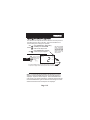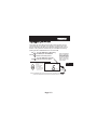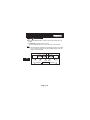
1
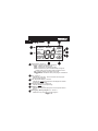
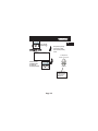
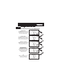
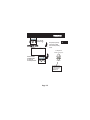
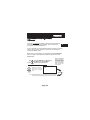
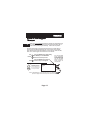
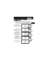
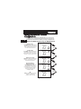
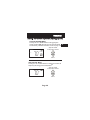
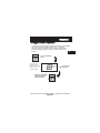
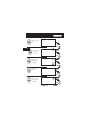
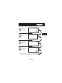
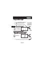
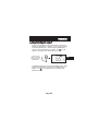
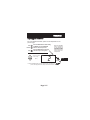
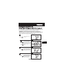
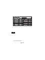
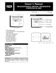
residential
THERMOSTAT
Digital
Thermostat
T1700
1-DAY
PROGRAMMABLE
up to 2-heat
& 1-cool
HEAT
COOL
CONFIGURABLE IN SETUP:
Auto or Manual changeover
Programmable or
Non-Programmable
HEAT
PUMP
Control up to 2 Heat &
1 Cool Stages
Backlit Display & Button
Legends
Aux Heat Indicator
Outdoor Sensor Ready
Accepts EZ Programmer
Accepts Optional IR
Remote Control
Accepts Comfort Call
Phone Control Accessory
Use with most Air Conditioning & Heating Systems including: 1 or 2 Stage
Electric Cooling & 3 Stage Gas Heating, Heat Pump, Electric or Hydronic Heat.
OWNER’S
MANUAL
Venstar Inc. 08/07
CAUTION
Follow the Installation Instructions before proceeding.
Set the thermostat mode to “OFF” prior to changing
settings in setup or restoring Factory Defaults.
This device complies with Part 15 of the FCC Rules. Operation is
subject to the following two conditions: (1) this device may not cause
harmful interference, and (2) this device must accept any interference
received, including interference that may cause undesired operation.
Thermostat
T1700
c
FC
Tested to Comply
with FCC Standards
4Z95
FOR HOME OR OFFICE USE
Page i
How to Use This Manual
The Table of Contents divides the thermostat features into sections
making it easier to quickly find information.
The first page of each section contains a more detailed Contents of each
section, such as the example page shown below.
SECTION 14
Timers and Deadbands
Header shows section #
and title of section
Section 14 Contents:
Adjusting the Heat/Cool
Differential..............................14.2
Adjusting the Cycles
Per Hour..................................14.3
Adjusting the Deadband..........14.4
Adjusting the Minutes of
Run-Time Before the
14
Next Stage...............................14.6
Selecting 2nd Stage Turn
Off Temperature.....................14.7
Section contents
Visible section tab
on the side of the
page
Section and page #
Page 14.1
In addition, this manual also has an Index to help you find any information
regarding this thermostat quickly.
Page ii
Glossary of Terms
Auto-Changeover: A mode in which the thermostat will turn on
the heating or cooling based on room temperature demand.
Cool Setpoint: The warmest temperature that the space should
rise to before cooling is turned on (without regards to
deadband).
Deadband: The number of degrees the thermostat will wait, once
setpoint has been reached, before energizing heating or cooling.
Differential: The forced temperature difference between the
heat setpoint and the cool setpoint.
Heat Setpoint: The coolest temperature that the space should
drop to before heating is turned on (without regards to
deadband).
Icon: The word or symbol that appears on the thermostat
display.
Mode: The current operating condition of the thermostat (i.e. Off,
Heat, Cool, Auto, Program On).
Non-Programmable Thermostat: A thermostat that does not
have the capability of running the Time Period Programming.
Programmable Thermostat: A thermostat that has the capability
of running the Time Period Programming.
Temperature Swing: Same as Deadband.
Time Period Programming: A program that allows the
thermostat to automatically adjust the heat setpoint and/or the
cool setpoint based on the time of day.
Page iii
Table of Contents
Getting to Know Your
Thermostat
Quick Start
1
2
Setting Clock
3
Basic Operation
4
Viewing the Outdoor
5
Temperature
Programming the
6
Daily Schedule
Programming the Fan
7
Operation
Thermostat Display
8
Options
Setting and Resetting
Equipment Run-Times 9
Electric Heat and
Heat Pump Operation 10
Timers and Deadbands 11
Factory Defaults and
12
Calibration
Accessories
13
Advanced Setup Table 14
Page iv
SECTION 1
Getting to Know Your Thermostat
1
Section 1 Contents:
Front Panel Buttons.....................1.2
Display Features...........................1.3
Page 1.1
1
Front Panel
Warmer Button
(glows red)
Backlit LCD Display
I2:00
Pm
[
]
sometimes referred
to as the UP button
74
COOL
AUTO
72
HEAT
Cooler Button
(glows blue)
Heat or Cool Demand Indicator Mode
Button
Red = Heat, Green = Cool
PLATINUM
[
eries
COMMERCIAL PROGRAMMABLE THERMOSTAT
I2:00
Pm
74
COOL
AUTO
72
HEAT
FAN
EMRG HT. OUTDOOR PROGRAM SET CLOCK
MODE
QUICK RELEASE FOR
ACCESSORY PORT
(pg. 13.1)
FAN
EMRG HT. OUTDOOR PROGRAM
Page 1.2
]
sometimes referred to as the
DOWN button
SET
CLOCK
11 Display Features
I8:88
Service Filter
AUTO
OFFON
88
I88 88
Am Program On Setup
Pm StartStop
COOL
Outside
AUXHEAT
Morning
DayNight
Evening
FanOn
Mode Indicators - Section 4
Selects the operational mode of the equipment.
HEAT - Indicates the heating mode.
COOL - Indicates the air conditioning mode.
AUTO - Indicates the system will automatically changeover
between heat and cool modes as the temperature varies.
OFF - Indicates heating and cooling is turned off.
PROGRAM ON - Indicates the time period program is enabled to
run.
Clock - Section 3
Indicates the current time. This clock is also used to program
the time period schedule.
Room Temperature Display - Section 5
Indicates the current room temperature and displays the outdoor
temperature when selected.
Desired Set Temperature - Section 4/5
Indicates desired room temperature(s).
Outside icon - Section 5
Indicates the temperature displayed is from the optional outdoor
sensor.
Morning, Day, Evening & Night icons - Section 6
Indicates the day part of the time period program.
Page 1.3
Display Features
I8:88
1
Service Filter
Pan UV Light
AUTO
OFFON
88
I88 88
Am Program On Setup
Pm StartStop
COOL
Outside
AUXHEAT
Morning
DayNight
Evening
FanOn
Setup icon - Sections 6-11
Indicates the thermostat is in the setup mode.
Fan On icon - Section 7
Indicates constant, continuous fan operation.
When Fan On is not lit - indicates the fan will only operate when
necessary to heat or to cool.
Service Filter icon - Section 9
Appears when the filter should be serviced under normal conditions.
Adjustable from 0 - 1950 hours of blower operation.
icon - Section 8
Indicates the keypad has been locked.
StartStop icon - Section 6
Appears when programming timer functions.
AuxHeat icon - Page 11.4
Indicates the Heat Pump is currently using 2nd stage electric
strip heat.
UV Light icon - Section 9
Appears when the UV bulb should be serviced under normal
conditions. Adjustable from 0 - 1990 days of operation.
Page 1.4
SECTION 2
Quick Start
2
Section 2 Contents:
Setting the Clock .........................2.2
Selecting the Heat or Cool
Mode............................................2.3
Selecting Your Desired
Temperature................................2.4
Using the Fan Button...................2.4
Note: Following the instructions in this section will allow you to
operate your thermostat using the factory default settings. These
settings are depicted in the illustrations throughout this manual.
Page 2.1
RAM SET CLOCK
M
2
Press the SET
CLOCK button
During Setup & Programming:
Setting the Clock
I2:00
Am
I
Setup
Pressing the UP or DOWN
buttons will modify the flashing
selection.
To adjust the
Clock or Day use
Press the SET
CLOCK button
to return to
normal operation.
RAM SET CLOCK
M
Buttons.
To adjust the time by
hours press and hold
the FAN button while
pressing the UP or
DOWN buttons.
Page 2.2
Selecting the Heat or Cool Mode
2
Select Mode by Pressing the MODE Button
Heating Only
The HEAT setting indicates the
temperature the room has to
reach before the furnace will
turn on to heat the room.
Cooling Only
The COOL setting indicates the
temperature the room has to
reach before the air conditioner
will turn on to cool the room.
I2:00
HEAT
I2:00
Time Schedule for
Heating or Cooling
The Program On setting will
activate the time period
programming for the cooling
or heating setpoint ONLY
(Morning, Day, Evening
& Night Periods).
Pm
Press
MODE
Pm
COOL
AUTO
HEAT
I2:00
Pm
Program On
76
Press
MODE
COOL
Day
I2:00
Off
OFF indicates both heating
and air conditioning
systems are turned off.
Press
MODE
COOL
I2:00
Heating or Cooling
AUTO will automatically select
heat or cool based on room
temperature demand.
70 6876
70 76
70 68
70
70
Pm
OFF
68
HEAT
Pm
Page 2.3
Press
MODE
Selecting Your Desired Temperature (adjusting the setpoints)
2
AUTO OR PROGRAM MODE
Pressing the UP or DOWN buttons in Auto or Program mode
will adjust both the heat and cool set temperatures
simultaneously.
I2:00
Adjust the desired
set temperature with the
76
70 68
Pm
COOL
AUTO
HEAT
Buttons.
HEAT OR COOL MODE
Pressing the UP or DOWN buttons in Heat or Cool mode will
adjust only the heat or cool set temperature.
I2:00
70
Pm
Adjust the desired
set temperature with the
76
COOL
Buttons.
Using the Fan Button
I2:00
Press
76
70 68
Pm
COOL
AUTO
HEAT
FanOn
FAN
Fan On indicates constant fan
operation. You may turn the fan
on even if the thermostat is in the
Off mode. Pressing the FAN button
toggles this feature on or off.
Page 2.4
SECTION 3
Setting the Clock
3
Section 3 Contents:
Setting the Clock..........................3.2
Note: During setup & programming pressing the UP or DOWN
buttons will modify the flashing selection.
Page 3.1
RAM SET CLOCK
M
Press the SET
CLOCK button
During Setup & Programming:
Setting the Clock
I2:00
Am
I
Setup
3
Pressing the UP or DOWN
buttons will modify the flashing
selection.
To adjust the
Clock or Day use
Press the SET
CLOCK button
to return to
normal operation.
RAM SET CLOCK
M
buttons.
To adjust the time by
hours press and hold
the FAN button while
pressing the UP or
DOWN buttons.
Page 3.2
SECTION 4
Basic Operation
4
Section 4 Contents:
Programmable or NonProgrammable Thermostat........4.2
Manual or Auto-Changeover
Thermostat..................................4.3
Selecting the Operating Mode.....4.4
Selecting Your Desired
Temperature................................4.8
Note: During setup & programming pressing the UP or DOWN
buttons will modify the flashing selection.
Page 4.1
Programmable or Non-Programmable
Thermostat
When the very simplest operation is desired, this thermostat may
be configured to be non-programmable, with or without AutoChangeover. Follow the step below.
4
If ‘NO’ is selected, the thermostat will lockout the Program On screen;
only the Off, Heat, Cool, and Auto screens may be accessed by
pressing the MODE button.
Select ‘YES’ if you would like your thermostat to be programmable,
then the Program mode will be accessible through the use of the
MODE button.
MODE
PROGRAM
Press the MODE button. While holding
the MODE, press the PROGRAM
button to enter Setup screens.
Program On Setup
YES
Select Yes if you would like
the thermostat to be programmable or No for non-programmable.
Note: Press the MODE
button momentarily
to move through the
setup screens. Press
and hold the MODE
button to move backwards through the
setup screens.
i
Press
NO
PROGRAM
Press the PROGRAM button to leave the Setup screens. If no buttons are
pressed, the display will leave the setup screens after 30 seconds.
Page 4.2
Manual or Auto-Changeover
Thermostat
4
When the very simplest operation is desired, this thermostat may
be configured to be a manual heat and cool thermostat, with or
without time period programmability. Follow the step below.
The thermostat may be programmed to function as a Heat Only or
Cool Only thermostat by selecting ‘NO’ in the setup screen below.
This will lockout the Auto-Changeover screen and only allow the Off,
Heat, Cool, and Program On screens to be accessed.
MODE
PROGRAM
MODE
Press the MODE button. While holding
the MODE, press the PROGRAM
button to enter Setup screens.
Note: Press the MODE
button momentarily
to move through the
setup screens. Press
and hold the MODE
button to move backwards through the
setup screens.
Press the MODE button repeatedly
until this setup screen appears.
Setup
YES
Select Yes if you would
like the thermostat to
be Auto-Changeover or
No for a Heat Only and
Cool Only Thermostat.
2
AUTO
Press
NO
PROGRAM
Press the PROGRAM button to leave the Setup screens. If no buttons are
pressed, the display will leave the setup screens after 30 seconds.
Page 4.3
Operating Mode when the Thermostat
is Configured to be:
NON-PROGRAMMABLE WITH MANUAL-CHANGEOVER - If the
thermostat is configured to be a non-programmable thermostat
with Manual-Changeover, the following screens will be available
by pressing the MODE button.
4
Select the Mode by Pressing the MODE Button
Heating Only
The HEAT setting indicates the
temperature the room has to
reach before the furnace will
turn on to heat the room.
Cooling Only
The COOL setting indicates the
temperature the room has to
reach before the air conditioner
will turn on to cool the room.
I2:00
HEAT
I2:00
Press
MODE
Pm
COOL
I2:00
Off
OFF indicates both heating
and air conditioning
systems are turned off.
70 68
76
70
70
Pm
OFF
Pm
Page 4.4
Press
MODE
Operating Mode when the Thermostat
is Configured to be:
NON-PROGRAMMABLE WITH AUTO-CHANGEOVER - If the
thermostat is configured to be a non-programmable thermostat
4 with Auto-Changeover, the following screens will be available by
pressing the MODE button
Select the Mode by Pressing the MODE Button
Heating Only
The HEAT setting indicates the
temperature the room has to
reach before the furnace will
turn on to heat the room.
Cooling Only
The COOL setting indicates the
temperature the room has to
reach before the air conditioner
will turn on to cool the room.
I2:00
HEAT
I2:00
Pm
Press
MODE
Pm
COOL
AUTO
HEAT
I2:00
Off
OFF indicates both heating
and air conditioning
systems are turned off.
Press
MODE
COOL
I2:00
Heating or Cooling
AUTO will automatically select
heat or cool based on room
temperature demand.
70 68
76
70
76
70 68
70
Pm
OFF
Pm
Page 4.5
Press
MODE
Operating Mode when the Thermostat
is Configured to be:
PROGRAMMABLE WITH MANUAL-CHANGEOVER - If the thermostat is
configured to be a programmable thermostat with Manual-Changeover,
the following screens will be available by pressing the MODE button.
4
Select the Mode by Pressing the MODE Button
Heating Only
The HEAT setting indicates the
temperature the room has to
reach before the furnace will
turn on to heat the room.
Cooling Only
The COOL setting indicates the
temperature the room has to
reach before the air conditioner
will turn on to cool the room.
Time Schedule for
Heating Only
The HEAT Program On setting
will activate the time period
program for the heating
setpoint ONLY (Morning, Day,
Evening & Night Periods).
Time Schedule for
Cooling Only
The COOL Program On setting
will activate the time period
program for the cooling
setpoint ONLY (Morning, Day,
Evening & Night Periods).
I2:00
HEAT
I2:00
Press
MODE
Pm
COOL
I2:00
Day
I2:00
Pm
Program On
HEAT
Pm
Press
MODE
Press
MODE
Program On
COOL
Day
I2:00
Off
OFF indicates both heating
and air conditioning
systems are turned off.
70 6876
70
70 6876
70
70
Pm
OFF
Pm
Page 4.6
Press
MODE
Operating Mode when the Thermostat
is Configured to be:
4
PROGRAMMABLE WITH AUTO-CHANGEOVER - If the thermostat is
configured to be a programmable thermostat with Auto-Changeover,
the following screens will be available by pressing the MODE button.
Select the Mode by Pressing the MODE Button
Heating Only
The HEAT setting indicates the
temperature the room has to
reach before the furnace will
turn on to heat the room.
Cooling Only
The COOL setting indicates the
temperature the room has to
reach before the air conditioner
will turn on to cool the room.
I2:00
HEAT
I2:00
Time Schedule for
Heating or Cooling
The Program On setting will
activate the time period
programming for the cooling
or heating setpoint ONLY
(Morning, Day, Evening
& Night Periods).
Off
OFF indicates both heating
and air conditioning
systems are turned off.
Press
MODE
Pm
COOL
I2:00
Heating or Cooling
AUTO will automatically select
heat or cool based on room
temperature demand.
70 6876
70 76
70 6876
70 68
70
Pm
Press
MODE
Pm
COOL
AUTO
HEAT
I2:00
Pm
Program On
Press
MODE
COOL
Day
I2:00
OFF
HEAT
Press
Pm
Page 4.7
MODE
Selecting Your Desired Temperature (adjusting setpoints)
AUTO OR PROGRAM MODE
Pressing the UP or DOWN buttons in Auto or Program
modes will adjust both the heat and cool set temperatures
simultaneously. For more information on this see page 11.2.
I2:00
76
70 68
Pm
Adjust the desired
set temperature with the
COOL
AUTO
HEAT
buttons.
HEAT OR COOL MODE
Pressing the UP or DOWN buttons in Heat or Cool modes will
adjust only the heat or cool set temperature.
I2:00
70
Pm
76
Adjust the desired
set temperature with the
COOL
buttons.
Page 4.8
4
SECTION 5
Viewing the Outdoor Temperature
5
Section 5 Contents:
Viewing the Outdoor
Temperature..............................5.2
Page 5.1
Viewing the Outdoor Temperature
This requires an outdoor sensor (optional accessory) to be installed
(see page 4.6 of the Installation Instructions). To read the
temperature from the Outdoor Sensor, press the OUTDOOR
button. The display will then show the current outdoor temp5
erature.
EMRG HT. OUTDOOR PROGRAM
Press the OUTDOOR
button.
The current outdoor
temperature will be
displayed. This reading
is from the sensor
connected to RS2.
83
Press the OUTDOOR
button to return to
normal operation.
Outside
Current outdoor
temperature.
EMRG HT. OUTDOOR PROGRAM
Note: If no sensors are connected 2 dashes [- -] will appear on the display.
Page 5.2
SECTION 6
Programming the Daily Schedule
Section 6 Contents:
6
Programming a Daily
Schedule...................................6.2
Page 6.1
Programming a Daily Schedule
Press
PROGRAM
Press the PROGRAM button to enter time period programming.
6:00
Am
6
Start
Adjust the start time
for Morning.
Morning
Press
MODE
6:00
78
Am
Adjust the cooling
setpoint for Morning.
(35 - 99 )
COOL
Morning
Press
MODE
6:00
78
Am
Adjust the heating
setpoint for Morning.
(35 - 99 )
COOL
70
HEAT
Morning
8:00
Am
Press
MODE
Start
Adjust the start time
for Day.
Day
Press
MODE
Page 6.2
Continued
8:00
Am
Start
Adjust the start time
for Day.
Day
Press
MODE
6
8:00
85
Am
COOL
Adjust the cooling
setpoint for Day.
(35 - 99 )
Day
Press
MODE
8:00
85
Am
Adjust the heating
setpoint for Day.
COOL
62
HEAT
(35 - 99 )
Day
Press
MODE
6:00
Pm
Start
Adjust the start time
for Evening.
Evening
Press
MODE
6:00
Pm
Adjust the cooling
setpoint for Evening.
78
COOL
(35 - 99 )
Press
Evening
Page 6.3
MODE
Continued
6:00
78
Pm
Adjust the heating
setpoint for Evening.
COOL
70
HEAT
(35 - 99 )
Evening
Press
MODE
I0:00
6
Pm
Start
Adjust the start time
for Night.
Night
Press
MODE
I0:00
Pm
Adjust the cooling
setpoint for Night.
(35 - 99 )
82
COOL
Night
Press
MODE
I0:00
Pm
Adjust the heating
setpoint for Night
82
COOL
(35 - 99 )
Night
62
HEAT
Press
PROGRAM
Press the PROGRAM button to leave the Setup screens. If no buttons are
pressed, the display will leave the setup screens after 30 seconds.
Page 6.4
SECTION 7
Programming the Fan Operation
Section 7 Contents:
7
Using the Fan Button.................7.2
Setting the Fan-Off Time
Delay..........................................7.3
Page 7.1
Using the Fan Button
When the fan is set for automatic operation it will energize any time
there is a call for heating or cooling, otherwise the fan will remain off.
Pressing the FAN button will energize the fan and display the FanOn
icon on the thermostat display. To operate the fan in the automatic
mode, press the FAN button again and the FanOn icon will disappear.
Press
FAN
I2:00
76
70 68
Pm
COOL
AUTO
HEAT
FanOn
Fan On indicates constant fan
operation. You may turn the fan
on even if the thermostat is in the
Off mode. Pressing the FAN button
toggles this feature on or off.
Page 7.2
7
Setting the Fan-Off Time Delay
To increase the cooling efficiency of your unit, the thermostat may be
programmed to continue running the fan after a call for cooling has
been satisfied. This delay may be set for 30, 60, or 90 seconds. If
the Fan Off Delay is set for zero seconds, the fan will not energize
after a call for cooling has been satisfied.
7
MODE
PROGRAM
MODE
Press the MODE button. While holding
the MODE, press the PROGRAM
button to enter Setup screens.
Note: Press the MODE
button momentarily
to move through the
setup screens. Press
and hold the MODE
button to move backwards through the
setup screens.
Press the MODE button repeatedly
until this setup screen appears.
:00
Setup
3
Set the Fan Off Delay
to 0, 30, 60, or 90
seconds.
FanOn
Press
PROGRAM
Press the PROGRAM button to leave the Setup screens. If no buttons are
pressed, the display will leave the setup screens after 30 seconds.
Page 7.3
SECTION 8
Thermostat Display Options
Section 8 Contents:
Turning On/Off the
Backlight...................................8.2
8
Programming the Thermostat
to Display Temperature in
Fahrenheit or Celsius..............8.2
Locking/Unlocking the
Keypad......................................8.3
Page 8.1
Turning On/Off the Backlight
MODE
PROGRAM
MODE
Press the MODE button. While holding
the MODE, press the PROGRAM
button to enter Setup screens.
Press the MODE button repeatedly
until this setup screen appears.
8
Setup
Select backlight operation:
AUTO - Light from 6pm to
6am nightly.
ON - Light continuously.
OFF - Light for 8 seconds
after a button press.
Note: Press the MODE
button momentarily
to move through the
setup screens. Press
and hold the MODE
button to move backwards through the
setup screens.
4
AUTO
Press
MODE
Programming the Thermostat to Display
Temperature in Fahrenheit or Celsius
Setup
f
C
Select thermostat
operation in degrees
Fahrenheit or Celsius.
F
5
Press
PROGRAM
Press the PROGRAM button to leave the Setup screens. If no buttons are
pressed, the display will leave the setup screens after 30 seconds.
Page 8.2
Locking/Unlocking the Keypad
To prevent unauthorized use of the thermostat, the front panel
buttons may be disabled. To disable, or ‘lock’ the keypad, press
and hold the MODE button. While holding the MODE button,
press the UP and DOWN buttons together. The
icon will
appear on the display, then release the buttons.
I2:00
Press all three
buttons in the order
outlined above for
keypad lockout
85
65 55
Pm
COOL
AUTO
HEAT
MODE
To unlock the keypad, press and hold the MODE button. While
holding the MODE button, press the UP and DOWN buttons
together. The
icon will disappear from the display, then
release the buttons.
Page 8.3
8
SECTION 9
Setting and Resetting Equipment Run-Times
Section 9 Contents:
9
Setting and Resetting the
Service Filter (Fan Run-Time)
Alert........................................9.2
Setting and Resetting the UV
Light Run-Time Alert.............9.3
Page 9.1
How to Set and Reset the Service Filter
(Fan Run-Time) Alert
This counter keeps track of the number of hours of fan run-time
whether the fan is energized in the Heating or Cooling modes, or in
stand alone fan operation. The Service Filter icon will appear after the
preset number of hours of fan run-time in step #7 (below) has been
achieved. Setting this counter to zero in step #7 will prevent the
Service Filter icon from ever appearing.
MODE
PROGRAM
MODE
Press the MODE button. While holding
the MODE, press the PROGRAM
button to enter Setup screens.
Press the MODE button repeatedly
until this setup screen appears.
Hours the fan has
run since last reset
Press
Reset the counter to 0 to
remove the Service Filter
icon from the display.
0
Setup
Service Filter
Note: Press the MODE
button momentarily
to move through the
setup screens. Press
and hold the MODE
button to move backwards through the
setup screens.
6
FAN
Press
Adjust the number of
hours, in increments of
50, the fan will run
before the Service
Filter icon appears on
the display. 0 = off.
0
Service Filter
Setup
7
MODE
Press
PROGRAM
(0 - 1950 hours)
Press the PROGRAM button to leave the Setup screens. If no buttons are
pressed, the display will leave the setup screens after 30 seconds.
Page 9.2
9
How to Set and Reset the UV Light
Run-Time Alert
This counter keeps track of the number of days since the UV Light
counter has been reset. The UV Light icon will appear after the
number of days has been achieved, as shown in step #9 (below).
Setting the counter to zero in Step #9 will prevent the Service UV
Light icon from ever appearing.
MODE
9
PROGRAM
MODE
Press the MODE button. While holding
the MODE, press the PROGRAM
button to enter Setup screens.
Press the MODE button repeatedly
until this setup screen appears.
Days since the UV Light
icon has been reset
0
Press
Reset the counter to 0 to
remove the Service UV
Light icon from the display.
Note: Press the MODE
button momentarily
to move through the
setup screens. Press
and hold the MODE
button to move backwards through the
setup screens.
Setup
8
Setup
9
Service
UV Light
FAN
MODE
Press the MODE button repeatedly
until this setup screen appears.
0
Adjust the number of days
in increments of 10 before
the UV Light icon appears
on the display. 0 = off.
Service
UV Light
(0 - 1990 days)
Press
PROGRAM
Press the PROGRAM button to leave the Setup screens. If no buttons are
pressed, the display will leave the setup screens after 30 seconds.
Page 9.3
SECTION 10
Electric Heat and Heat Pump Operation
Section 10 Contents:
Viewing the Heat Pump and
Reversing Valve Jumper
10
Setting.....................................10.2
Viewing the Electric Heat
Jumper Setting.......................10.3
Using Emergency Heat............10.4
Page 10.1
Viewing the Heat Pump and
Reversing Valve Jumper Settings
Steps 10 and 11 are ‘Read Only’ and may only be set with the
jumpers on the circuit board of the thermostat.
MODE
PROGRAM
MODE
Press the MODE button. While holding
the MODE, press the PROGRAM
button to enter Setup screens.
Press the MODE button repeatedly
until this setup screen appears.
10
Setup
ON = Heat Pump
operation
OFF = Gas Electric
operation
Note: Press the MODE
button momentarily
to move through the
setup screens. Press
and hold the MODE
button to move backwards through the
setup screens.
I0
OFF
Press
Setup
O
Indicates that the
thermostat jumper
is set for an O
reversing valve
(energize in cooling)
or a b reversing valve
(energize in heating).
Ii
MODE
Press
PROGRAM
Press the PROGRAM button to leave the Setup screens. If no buttons are
pressed, the display will leave the setup screens after 30 seconds.
Page 10.2
Viewing the Electric Heat Jumper Setting
Placing the jumper on ELEC will cause the thermostat to turn on the
fan immediately any time there is a heat demand. Since most gas
furnaces control the fan, this feature should be off unless it is
necessary for the thermostat to energize the fan with first stage heat.
Step 12 is ‘Read Only’ and may only be set with the jumpers on the
circuit board of the thermostat (see page 4.3 of the Installation
Instructions).
Note: Press the MODE
MODE
PROGRAM
MODE
Press the MODE button. While holding
the MODE, press the PROGRAM
button to enter Setup screens.
Press the MODE button repeatedly
until this setup screen appears.
Setup
ON indicates that the
thermostat jumper is
set for Electric Heat
operation, or OFF for
Gas/Electric or Heat
Pump operation.
OFF
EH
button momentarily
to move through the
setup screens. Press
and hold the MODE
button to move backwards through the
setup screens.
I2
Press
PROGRAM
Press the PROGRAM button to leave the Setup screens. If no buttons are
pressed, the display will leave the setup screens after 30 seconds.
Page 10.3
10
Using Emergency Heat
ENTER EMERGENCY HEAT: Only available if you have a Heat Pump
installed. To initiate the Emergency Heat feature, press the EMER
HT. button. The Cool setpoint display will read ‘EH’
(emergency heat).
Press for
Emergency Heat
N
10
EMRG HT. OUTD
I2:00
73
Pm
74
HEAT
OPERATION: During Emergency Heat operation the
thermostat will turn on the fan and the 2nd stage of heat
when there is a demand for heat. Also during Emergency
Heat the 1st stage of heating or cooling will be unavailable.
EXIT EMERGENCY HEAT: Follow the same steps as entering
Emergency Heat by pressing the EMER HT. button. During
Emergency Heat, only OFF and HEAT modes are available by
pressing the MODE button.
Page 10.4
SECTION 11
Timers and Deadbands
Section 11 Contents:
Adjusting the Heat/Cool
Differential..............................11.2
Adjusting the Cycles
Per Hour..................................11.3
Adjusting the Deadband..........11.4
11
Page 11.1
Adjusting the Heat/Cool Differential
The Heat and Cool setpoints will not be allowed to come any closer to
each other than the value in this step. This minimum difference is
enforced during Auto-Changeover operation.
MODE
PROGRAM
MODE
Press the MODE button. While holding
the MODE, press the PROGRAM
button to enter Setup screens.
Press the MODE button repeatedly
until this setup screen appears.
2
Setup
11
Note: Press the MODE
button momentarily
to move through the
setup screens. Press
and hold the MODE
button to move backwards through the
setup screens.
Adjust the minimum
difference between
cooling & heating
setpoints.
(0 - 6 )
I3
COOL
HEAT
Press
PROGRAM
Press the PROGRAM button to leave the Setup screens. If no buttons
are pressed, the display will leave the setup screens after 30 seconds.
Note: To increase the spread between the heating and cooling
setpoints, press the MODE button until only the heat setpoint is
displayed. Adjust the desired setpoint. Press the MODE button
until only the cool setpoint is displayed. Adjust the desired setpoint.
Press the MODE button again to enter the Auto-Changeover mode
where both the heat and cool setpoints are displayed.
Page 11.2
Adjusting the Cycles Per Hour
The Cycles Per Hour setting may limit the number of times per hour
your HVAC unit may energize. For example, at a setting of 6 cycles
per hour the HVAC unit will only be allowed to energize once every 10
minutes. The Cycles Per Hour limit may be overridden and reset by
pressing the UP or DOWN buttons on the thermostat.
MODE
PROGRAM
MODE
Press the MODE button. While holding
the MODE, press the PROGRAM
button to enter Setup screens.
Note: Press the MODE
button momentarily
to move through the
setup screens. Press
and hold the MODE
button to move backwards through the
setup screens.
Press the MODE button repeatedly
until this setup screen appears.
6
Setup
Select the cycles per
hour limit.
d=cycles per hour
limit defeated.
d1=d + defeat 5 min.
compressor lockout.
(d1, d, 2 - 6)
I4
Cy
Press the PROGRAM button to leave the Setup screens. If no buttons are
pressed, the display will leave the setup screens after 30 seconds.
Page 11.3
11
Press
PROGRAM
Adjusting the Deadband
MULTI-STAGE OPERATION - Controls up to two Heat and one Cool
stages.
The 2nd Stage of heat is turned on when:
(A) The 1st Stage has been on for a minimum of two minutes.
And
(B) The temperature spread from the setpoint is equal to or greater
than: the setpoint plus the 1st stage deadband (step #15, next
page), plus two degrees.
Cooling
Heating
11
2nd Stage
turn on
Deadband
Deadband
Deadband
db 2
(fixed 2 )
db 1
(adj. 1-6 )
db 1
(adj. 1-6 )
1st Stage
turn on
DECREASE
Heat
Setpoint
Cool
Setpoint
TEMPERATURE
Page 11.4
1st Stage
turn on
INCREASE
Adjusting the Deadband
For more detailed information, please see the explanation on the
previous page.
MODE
PROGRAM
MODE
Press the MODE button. While holding
the MODE, press the PROGRAM
button to enter Setup screens.
Note: Press the MODE
button momentarily
to move through the
setup screens. Press
and hold the MODE
button to move backwards through the
setup screens.
Press the MODE button repeatedly
until this setup screen appears.
2
Setup
Adjust the deadband
for the 1st stage.
(1 - 6 )
I5
Press the PROGRAM button to leave the Setup screens. If no buttons are
pressed, the display will leave the setup screens after 30 seconds.
Page 11.5
Press
PROGRAM
11
SECTION 12
Factory Defaults and Calibration
Section 12 Contents:
Resetting the Thermostat to the
Factory Default Settings........12.2
Calibrating the Temperature
Sensor.....................................12.3
12
Page 12.1
Resetting the Thermostat to the
Factory Default Settings (for default values see page 14.1)
If, for any reason, you desire to return all the stored settings back to
the factory default settings, follow the instructions below.
WARNING: This will reset all Time Period and Advanced
Programming to the default settings. Any information entered
prior to this reset may be permanently lost.
I2:00
Su
MODE
MODE
FAN
Place the thermostat in the
OFF mode.
Press and hold the MODE
button. While holding the
MODE button, press and hold
the FAN button for 5 seconds.
All icons will appear on the
display.
FAN
After all of the icons appear,
release the MODE and FAN
buttons. Then press and hold
the FAN button for 5 seconds.
MODE
After the letters Fd appear on
the display (Factory Default),
release the FAN button. Press
the MODE button once to
return to normal operation.
OFF
I8:88
72
88
I88 88
Pm
Am Program On Setup
Pm StartStop
Service Filter
AUTO
OFFON
COOL
Outside
AUXHEAT
Morning
DayNight
Evening
FanOn
I2:00
OFF
Page 12.2
Pm
72
12
Calibrating the Temperature and Humidity Sensors
Under normal circumstances it will not be necessary to adjust the
calibration of the temperature and humidity sensors. If calibration is
required, please contact a trained HVAC technician to correctly
perform the following procedure.
I2:00
Su
MODE
MODE
12
FAN
Place the thermostat in the
OFF mode.
Press and hold the MODE
button. While holding the
MODE button, press and hold
the FAN button for 5 seconds.
All icons will appear on the
display.
OFF
I8:88
72
88
I88 88
Pm
Am Program On Setup
Pm StartStop
Service Filter
AUTO
OFFON
Morning
DayNight
Evening
FanOn
COOL
Outside
AUXHEAT
PRESS
THERMOSTAT SENSOR
Press the UP and DOWN buttons
at the same time twice. The
thermostat temperature will be
displayed and may be calibrated
using the UP or DOWN buttons.
TWICE
After calibration is complete, press the MODE button once to return to
normal operation.
Page 12.3
CALIBRATE
SECTION 13
Accessories
ACCESSORY PORT - The RJ11 Jack is used to connect the
T1700 to the IR Receiver (ACC0431) for wireless communication
or the EZ Programmer (ACC0432) for easy downloading or
uploading of thermostat information.
The Accessory Port is located on
the bottom of the thermostat.
RJ11 Type Jack
IR RECEIVER / REMOTE CONTROL (optional accessory) - When the
IR Receiver is connected, the thermostat can be controlled using
an IR Remote Control. The thermostat may also interface with
other wireless systems in your home. For more information see the
manual for the IR Receiver (ACC0431).
EZ PROGRAMMER (optional accessory) - When the EZ Programmer is connected, the thermostat Time Period Programming and
Advanced Setup Programming can be stored into the EZ
Programmer’s memory. This information can then be uploaded
to other T1700 thermostats. For more information see the
manual for the (ACC0432).
13
COMFORT CALL (optional accessory) - When Comfort call is connected,
the thermostat’s Heating and cooling functionality may be accessed
and controlled through the phone. For more information see the
manual for Comfort Call (ACC0433).
Page 13.1
SECTION 14
Advanced Setup Table
Step#
Description
1 Programmable
Thermostat
2 Auto-Changeover
Thermostat
3 Fan Off Delay
4 Thermoglow
Backlight
5 F or C
6 Reset Service Filter
Icon
7 Service Filter Run
Time Set
Pg# Range Df * Step#
4.2 Yes/No
Yes
Description
8 Reset UV Light Icon
9 UV Light Run-Time
Set
4.3 Yes/No Yes
10 Heatpump Jumper
Setting
7.3 0, 30, 60, 0
11 Reversing Valve
90
Jumper Setting
8.2 Auto/On/ Auto
12 Electric Heat
Off
Minimum
Heat/Cool
13
8.2 F/C
F
Differential
9.2 read only - 14 Cycles Per Hour
15 Deadband/Temp.
9.2 0 - 1950 0
Swing
14
*Df = Factory Default Setting
Page 14.1
Pg# Range Df *
9.3 read only - 9.3 0 - 1990 0
10.2 read only - 10.2 read only - 10.3 read only - 11.2 0 - 6
2
11.3 d1, d, 2-6 6
11.5 1 - 6
2
SECTION 15
A
Accessory Port, 13.1
Alerts
see Run-Time
Auto
adjust temperature,
2.4, 4.8
changeover, 1.3, 11.2,
4.3, 4.5, 4.7, 14.1
differential, see
Differential
fan, 7.2
icon, 1.3
lockout, 4.3
mode, 2.3
AuxHeat icon, 1.4
B
b reversing valve, 10.2
Buttons
down, 1.2, 2.2, 2.4,
8.3,12.3
emer ht., 1.2, 10.4
fan, 1.2, 2.4, 7.2, 12.2
front panel, 1.2
mode, 1.2, 2.3, 4.2,
8.3, 12.2
outdoor, 1.2, 5.2
program, 1.2, 4.2, 6.2
Index
set clock, 1.2, 2.2
up, 1.2, 2.2, 8.3,
C
C, 8.2, 14.1
Calibration, 12.3
Celsius, 8.2
Clock
display, 1.3
setting, 2.2, 3.2
Compressor Lockout,
11.3
Cool
deadband, see
Deadband
droop, see Deadband
electric/heat pump,
10.2
icon, 1.3
indicator, 1.2
mode, 2.3
program, see
Program
setpoint, 2.3-2.4,
6.2-6.4
Cycles Per Hour, 11.3
14.1
Page 15.1
D
Day
icon, 1.3
programming, 6.3
setting, 1.2, 2.2, 3.2
Deadband
1st stage, 11.4-11.5,
14.1
Delay
fan-off, see Fan
Differential
heat and cool, 11.2,
14.1
Disabled Keypad
see Keypad Lockout
E
EH, 10.4
Electric Heating
AuxHeat icon, 1.4
jumper setting, 10.3
14.1
Emergency Heat,
10.4
EZ Programmer, 13.1
SECTION 15
F
F, 8.2, 14.1
Factory Defaults
caution, ii
resetting, 12.2
settings, 12.2
Fahrenheit, 8.2
Fan
button function, see
Buttons
off time delay, 7.3,
14.1
on during heat, see
Electric Heat
on icon, 1.4, 2.4, 7.2
run-time, 9.2
2nd stage heat, see
Emergency Heat
Fd, 12.2
Flashing Selection,
2.2
G
Gas Furnace
control the fan, 10.3
jumper, 10.2
Green Indicator, 1.2
Index
H
Heat
1st stage
deadband, see
Deadband
emergency heat,
10.4
2nd stage
emergency heat,
10.4
electric strip heat,
1.4
AuxHeat icon, 1.4
deadband, see
Deadband
droop, see Deadband
electric/heat pump,
10.2
icon, 1.3-1.4
indicator, 1.2
mode, 2.3
program, see
Program
setpoint, 2.3-2.4,
6.2-6.4
Heat Pump
AuxHeat, 1.4
emergency heat,
10.4
jumper setting, 10.2
Page 15.2
I
IR Receiver, 13.1
J
Jumpers
electric heat, 10.3
gas electric, 10.2
heat pump, 10.2,
14.1
reversing valve, 10.2,
14.1
K
Keypad Lockout, 1.4,
8.3
L
LCD, 1.2
Locked Indication
see Keypad Lockout
SECTION 15
M
Manual
changeover, 4.3-4.4,
4.6
cool, 4.3
heat, 4.3
Multi-stage
Operation, 11.4
N
Non-Programmable
Thermostat, 4.2,
4.4-4.5
O
O Reversing Valve,
10.2
Off Mode, 1.3, 2.3
Outdoor
button, see Buttons
icon, 1.3
sensor, 1.3, 5.2,
viewing temperature,
1.3, 5.2
Index
P
Program
daily schedule, 6.26.4
mode, 1.4, 4.6-4.7
On icon, 2.3
Programmable
Thermostat,
4.2, 4.6-4.7
R
Red Indicator, 1.2
Reset
thermostat settings,
see Factory Defaults
run-time
fan/filter, 9.2,
14.1
UV light, 9.3,
14.1
RS2, see Outdoor
Sensor
Run-Time
resetting, see Reset
setting,
service filter, 9.2
14.1
Page 15.3
UV light, 9.3,
14.1
S
Schedule
daily, see Program
Sensor
outdoor, see Outdoor
thermostat, see
Thermostat Sensor
Service
filter icon, see Reset
UV light, see Reset
Set Clock, see Clock
Setpoint
cool, see Cool
heat, see Heat
Setup Icon, 1.4
Simplest Operation,
4.2-4.3
T
Thermostat Sensor
calibrate, 12.3
Time, see Clock
Time Delay,
compressor lockout,
11.3
SECTION 15
Index
cycles per hour,
11.3, 14.1
Time Schedule,
see Program
U
UV Light
icon, 1.4
resetting, see Reset
run-time, see RunTime
setting, see Run-Time
W
Warranty, 16.1
Page 15.4
SECTION 16
Warranty
One-Year Warranty - This Product is warranted to be free from defects in material and workmanship.
If it appears within one year from the date of original installation, whether or not actual use begins
on that date, that the product does not meet this warranty, a new or remanufactured part, at the
manufacturer’s sole option to replace any defective part, will be provided without charge for the
part itself provided the defective part is returned to the distributor through a qualified servicing
dealer.
THIS WARRANTY DOES NOT INCLUDE LABOR OR OTHER COSTS incurred for diagnosing, repairing,
removing, installing, shipping, servicing or handling of either defective parts or replacement parts.
Such costs may be covered by a separate warranty provided by the installer.
THIS WARRANTY APPLIES ONLY TO PRODUCTS IN THEIR ORIGINAL INSTALLATION LOCATION AND
BECOMES VOID UPON REINSTALLATION.
LIMITATIONS OF WARRANTIES – ALL IMPLIED WARRANTIES (INCLUDING IMPLIED WARRANTIES OF FITNESS
FOR A PARTICULAR PURPOSE AND MERCHANTABILITY) ARE HEREBY LIMITED IN DURATION TO THE PERIOD
FOR WHICH THE LIMITED WARRANTY IS GIVEN. SOME STATES DO NOT ALLOW LIMITATIONS ON HOW
LONG AN IMPLIED WARRANTY LASTS, SO THE ABOVE MAY NOT APPLY TO YOU. THE EXPRESSED
WARRANTIES MADE IN THIS WARRANTY ARE EXCLUSIVE AND MAY NOT BE ALTERED, ENLARGED, OR
CHANGED BY ANY DISTRIBUTOR, DEALER, OR OTHER PERSON WHATSOEVER. ALL WORK UNDER THE
TERMS OF THIS WARRANTY SHALL BE PERFORMED DURING NORMAL WORKING HOURS. ALL
REPLACEMENT PARTS, WHETHER NEW OR REMANUFACTURED, ASSUME AS THEIR WARRANTY PERIOD
ONLY THE REMAINING TIME PERIOD OF THIS WARRANTY.
THE MANUFACTURER WILL NOT BE RESPONSIBLE FOR:
1. Normal maintenance as outlined in the installation and servicing instructions or owner’s
manual, including filter cleaning and/or replacement and lubrication.
2. Damage or repairs required as a consequence of faulty installation, misapplication,
abuse, improper servicing, unauthorized alteration or improper operation.
3. Failure to start due to voltage conditions, blown fuses, open circuit breakers or other
damages due to the inadequacy or interruption of electrical service.
4. Damage as a result of floods, winds, fires, lightning, accidents, corrosive environments or
other conditions beyond the control of the Manufacturer.
5. Parts not supplied or designated by the Manufacturer, or damages resulting from their use.
6. Manufacturer products installed outside the continental U.S.A., Alaska, Hawaii, and
Canada.
7. Electricity or fuel costs or increases in electricity or fuel costs for any reason whatsoever
including additional or unusual use of supplemental electric heat.
8. ANY SPECIAL INDIRECT OR CONSEQUENTIAL PROPERTY OR COMMERCIAL DAMAGE OF ANY
NATURE WHATSOEVER. Some states do not allow the exclusion of incidental or
consequential damages, so the above may not apply to you.
This warranty gives you specific legal rights and you may also have other rights which may vary
from state to state.
Page 16.1
P/N 88-595 Rev. 1