1
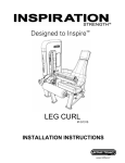
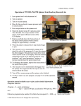
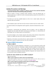
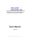
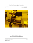
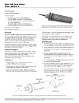
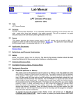
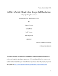
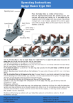
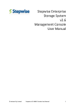
Headway Spin Coater Instruction Manual Roger Robbins 6/21/2007 The University of Texas at Dallas Erik Jonsson School of Engineering DOCUMENT TITLE: Headway Spin Coater Instruction Manual AUTHOR: Roger Robbins DOCUMENT NUMBER: SP2007-LI-001 Page 1 of 7 6/21/2007 Headway Spin Coater Instruction Manual Roger Robbins 6/21/2007 Table of Contents Headway Spin Coater Instruction Manual......................................................................... 2 Table of Contents .......................................................................................................... 2 Introduction.................................................................................................................... 3 Description..................................................................................................................... 3 Sign the Logbook........................................................................................................... 4 Substrate Centering....................................................................................................... 4 Programming the Controller .......................................................................................... 5 General ...................................................................................................................... 5 Programming Details ................................................................................................. 6 Program Execution ........................................................................................................ 7 Cleanup ......................................................................................................................... 7 DOCUMENT TITLE: Headway Spin Coater Instruction Manual AUTHOR: Roger Robbins DOCUMENT NUMBER: SP2007-LI-001 Page 2 of 7 6/21/2007 Headway Spin Coater Instruction Manual Roger Robbins 6/21/2007 Introduction The Headway Spinner enclosed in a stainless steel solvent hood was donated by TI to the UTD Clean Room. This manual spinner has a new controller, the Headway model PWM32, which allows a bit of programming similar to our new CEE spinner. We can use the Headway for small samples because it has facilities more amenable to tiny samples. It will be mandatory to clean this bowl after your job is complete. This paper describes how to program and use the system. Description The spinner system consists of a stainless steel solvent hood, a spin chuck on a motor shaft in the base of the hood deck, a motor controller sitting on top of the hood (out of solvent fumes), and a foot switch to start the spin cycle for coating. This system is labeled in Figure 1. Headway Spinner Controller Spin Bowl Air Gun Foot Switch showing red and green circles Figure 1. Headway Spinner enclosed in a SS Solvent Hood. DOCUMENT TITLE: Headway Spin Coater Instruction Manual AUTHOR: Roger Robbins DOCUMENT NUMBER: SP2007-LI-001 Page 3 of 7 6/21/2007 The spinner can accommodate sample sizes from about 1 to 8 inches. Anything smaller than an inch must use a spin chuck with Kapton tape covering the vacuum rings and one hole punched in the center of the Kapton to vacuum clamp the sample. This will prevent resist from sucking down the vacuum port in the chuck and gumming up the works. The spin motor can be programmed to ramp up and down for resist spreading and safe stopping. If there is an excess of solvent or resist, there are two holes in the bottom of the bowl that drain into two solvent containers below the deck. Unlike a toilet, the lid over the spin bowl is interlocked to prevent spinning with the lid up. Figure 2 shows the spin bowl with a photomask mounted on a spin chuck. Spin Bowl Resist/Solvent Drain holes Spin Bowl Lid Spin Bowl Lid Latch (Interlocked) Figure 2. Spin Bowl with photomask on spin chuck. The spin chucks are attached to the motor shaft via a D-shaped shaft and Dshaped hole in the bottom of the chuck socket with a small o-ring in it to seal the vacuum in. Note that the chuck surface must be completely clean before attempting to vacuum clamp a sample for spinning. This is extremely important to prevent samples from flying off at potentially high speeds and possibly causing injury. This spin motor can accelerate at 20,000 rpm/sec which can impart a rather high force to the wafer. Sign the Logbook When you approach the spinner for a job, the first thing that you do is sign the logbook. Violators of this policy will be prosecuted to the fullest extent of the law. Substrate Centering This is a manual spinner requiring manual centering of substrates. If the substrate is off-center too much, it will exert a centrifugal force on the vacuum chuck and attempt to fly off on its own. We will include a program named “0” that will spin the chuck at about 200 rpm for maybe 5 seconds as a test of centering. If the substrate wobbles more than ¼ inch, recenter the substrate and test it again. Repeat until the substrate spins at center. Do not change program #0; user programs will start at #1. DOCUMENT TITLE: Headway Spin Coater Instruction Manual AUTHOR: Roger Robbins DOCUMENT NUMBER: SP2007-LI-001 Page 4 of 7 6/21/2007 Programming the Controller General The Headway Model PWM32 controller is programmed via the membrane keys on the face of the controller, Figure 3. A recipe (identified by a number 0-9) consists of a sequence of steps. Steps inside a recipe are also identified with a number (0-9). This means that there are 10 possible programs with a maximum of 10 steps in each. Once a program step has been entered, it cannot be erased. If you need to erase an individual step, then you have to erase the entire program and start over. Any step underway can be immediately terminated by stepping on the red circle of the foot switch. Note also that the timer does not start until the spin chuck has ramped to its stable assigned speed. Also during development of a program, the programmer can temporarily alter the speed of the chuck by pressing the membrane keys across from the up and down speed arrows in the lower right of the keypad. In general, a program step must be terminated by something, usually time, but could be set to some other event, such as spinning chuck reaching zero velocity, or manual termination, etc. In the LCD display you can see the status of the controller: Current recipe number in the format of (current step - of – total steps), time, State (Ready, Review, Running, and Programming, Abort), vacuum mode (AU – Auto, MN – Manual), and a strange code in the last line. LCD Display Keypad Off/On Switch Figure 3. Headway Model PWM32 Controller DOCUMENT TITLE: Headway Spin Coater Instruction Manual AUTHOR: Roger Robbins DOCUMENT NUMBER: SP2007-LI-001 Page 5 of 7 6/21/2007 Programming Details Programming is rather simple and consists of setting a program number, adding steps and setting the step terminator. It is a good idea to write down your program before “winging” it on the controller keyboard since you cannot erase a step. Simple programs consist of parameters like speed (rpm), ramp acceleration (rpm/sec), spin time (sec), and ramp deceleration (rpm/sec). You may have several steps such as a resist spreading spin, a full speed spin to dry the resist, and a deceleration-to-zero step for program termination. The following example of programming will include three steps – use your own values instead of the ones I have listed in the example. • • • • Enter the program number: o Press “Recipe” o Press a number key to label the program o If you want to erase a program, press “Recipe”, then “Clear” and then the Recipe number. Select Step 1: o Press “Step” o Press a number key to indicate the step you are programming - 1 Press key “Speed/Ramp” Enter the desired spin speed – 1000 rpm and then “On or Enter” Press key “Speed/Ramp” again Enter the desired acceleration – 2000 rpm/sec and then “On or Enter” NOTE: The “Off or Clear” key will act as a backspace key to allow correcting an entry prior to pressing the “On or Enter” key. Set the Step Terminator (time): • Press key “Step Terminator” • Enter time via the numeric keypad – 1 sec then “On or Enter” Select Step 2: o Press “Step” o Press a number key to go to the next step – 2 Press key “Speed/Ramp” Enter the desired spin speed – 3700 rpm and then “On or Enter” Press key “Speed/Ramp” again Enter the desired acceleration – 5000 rpm/sec and then “On or Enter” Set the Step Terminator (time): • Press key “Step Terminator” • Enter time via the numeric keypad – 60 sec then “On or Enter” Select Step 3: o Press “Step” o Press a number key to go to the next step – 3 Press Key “Speed/Ramp” Enter the desired spin speed – 0 rpm and then “On or Enter Press key “Speed/Ramp again Enter the desired deceleration – 1000 rpm and “On or Enter” DOCUMENT TITLE: Headway Spin Coater Instruction Manual AUTHOR: Roger Robbins DOCUMENT NUMBER: SP2007-LI-001 Page 6 of 7 6/21/2007 o o Set the Terminator (time) • Press key “Step Terminator” • Enter the time – 0 sec then “On or Enter” Terminate the programming session by pressing “Step” and then the number 0. Press “Vacuum on/auto” toggle key to insure that the vacuum is controlled automatically. The above program example details three different actions: a short spin for resist spreading, a full spin speed for a longer time to dry the film and a ramp to zero to prevent the substrate from flying off at a 20,000 rpm/sec deceleration at the end. Program Execution The above program would be executed in the following procedure: • • • • • • • • Sign the logbook Load a wafer onto the spin chuck and test its centering via program “0”. o Place the wafer on the spin chuck as close to center as you can. o Press “Recipe” and then 0 to select the centering test program o Step on the Green circle on the footswitch to start the slow spin. o Recenter the wafer if necessary and repeat stepping on the green circle on the footswitch until the wafer wobble is less than ¼ inch. o Wafer is now sufficiently centered. Press “Recipe” and then 1 Close the lid. Apply photoresist to the substrate Press on the green circle on the footswitch – the spin program executes. o Note that if anything goes wrong you can press the Red circle on the footswitch to immediately stop the spin program. Vacuum clamping is released at the conclusion of the program and you can remove your coated substrate. Clean the spinner bowl with acetone and a rag. Cleanup After you have coated all your substrates it is mandatory that you clean up the coater, cleanup all traces of photoresist using acetone and wipes. Used wipes go into the solvent waste can. DOCUMENT TITLE: Headway Spin Coater Instruction Manual AUTHOR: Roger Robbins DOCUMENT NUMBER: SP2007-LI-001 Page 7 of 7 6/21/2007